
milling radius without rotary table manufacturer

You say you have a rotary table. Use it. Make a setup similar to the photos in RichR"s post. Do conventional milling, which we would find in that last photo where the end mill rotates to the right, and the table would be rotated in a counter clockwise direction, so that the cutter and work are moving in opposite directions. For a plate 3/8 thick I suggest going with a four flute end mill. It will give a fine finish and have less chip load per tooth than a two flute.

Agree with John that it will work just fine but setting up will be more than a chore if you need a decently accurate ball curve rather than a simple blending radius. Even with a simple radius setting needs to be pretty good if the results aren"t to appear a bit wonky. The Mk1 human eyeball is good at spotting such errors. If going for a full good ball it can be very hard to keep straight where remaining errors are and what adjustment corrects them once you"ve got to the "fairly good but not good enough" stage.
That said if you have a boring head it can be used as a basis for an effective up"n over type ball turning tool without a vast amount of work. Assuming you have a reasonable starter lump in the useful bits box I"d estimate that a very useable up"n over tool could be made in less than twice the average time taken to set-up what you propose and produce a nice workpiece. One made you have the up"n over tool ready to go at any time but the rotary table on the mill has to be set from scratch for each use.

The channel for the slide needs to be positioned in a manner that the back of the slide is 1.98 inches away from the 3 inch point of the rotary table. And 3 inches minus 1.980 is 1.02 (3.0 - 1.980 = 1.02) so the rear of the channel needs to be machined 1.02 inches away from the center.
If you mill that channel 1.01 inches wide and so that it stops 1.02 inches from the middle of the rotary table, you should be able to set the slide in the channel so that the rotary table generates the 3 inch front radius of the RM06 in the correct position.
Once you have the slide positioned correctly and bolted down to your fixture, you’ll need to use an indicator to make sure the slide is perfectly straight. Adjust the straightness on your rotary table until there"s no run-out along the x axis.
Start machining the radius by using the rotary table to move the slide rather than the x/y movement of your table. Do so in 5000th increments. Machine it closer and closer to the 3 inch radius in these small increments.

The TR160 5 Axis Rotary Tables, manufactured by Haas, consist of dual axis Trunnion rotary table that is capable of tilting up to 160 mm. It also has a scale assessment ...
The TR210 is HAAS"S rotary table developed and configured to be integrated with HAAS"S mills 4th and 5th axis drivers to provide complete and optimum operation. It has a diameter of 210 mm made from trunnion ...
... space with high load capacity. The individual rotary tables are equipped with Harmonic Drive units, which ensure high moment load capacities and high concentricity and axial runout accuracies.
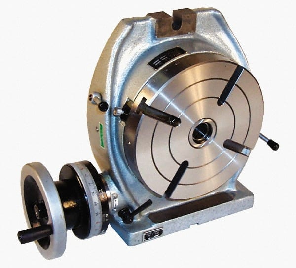
The work table is graduated 360 degrees around its circumference and is driven by a precision Worm and Gear providing a 90:1 reduction ratio. One turn of the Handle moves the Table through 4 degrees. ...
... Tilt-Yaw (A/B) two-axis rotary assembly provides high-speed machining capabilities for complex 3D part geometries. The precision-aligned system allows accurate positioning on a hemispherical surface. ...
... ) MDR two-axis rotary assembly provides high-speed machining capabilities for complex 3D part geometries. The precision-aligned system allows accurate positioning on a hemispherical surface. Uses cost-effective ...
... ) MDR two-axis rotary assembly provides high-speed machining capabilities for complex 3D part geometries. The precision-aligned system allows accurate positioning on a hemispherical surface. Uses cost-effective ...
Our FÖRSTER swivel welding tables offer maximum working comfort for all-round welding of complex assemblies. Ideal for all tasks due to a variable arrangement of our patented T-slot system.
The hydrostatic rotary tables from ZOLLERN impress with their durability and a high concentricity and axial runout accuracy. Thanks to the ZOLLERN bearing clearance compensator, the optimal pocket pressure ...
... the table is the rotation, the user may require the rotary table for drilling operations and milling. Using the servo drives in conjunction with the machine CNC control ...

If the workpiece is mounted on a rotary table and the head of the milling machine is tilted it is possible to machine various concave and convex surfaces using a boring head. It would be possible to do this using a fly cutter but it is easier to set up with a boring head.
In all of these cases it is essential that the axis of the rotary table is in the same plane as that of the spindle in the x/z plane. The axis of the sphere that the surface being cut is part of will be coaxial with the axis of the rotary table the movement of the cutter to the workpiece changes because the milling table is raised.
If the axis of the boring head is co-planar with the axis of the rotating table then, if the boring head rotates in a circle each point on this circle is the same distance from the intersection of the axis of the boring head and the rotating table regardless of the rotation of the rotating table.
The diameter of the sphere is solely determined by the diameter of the cutting circle, that is, the diameter of the boring head and the distance from the top (or bottom) of the cutting circle and the point where the axis if the boring head and the axis of the rotary table. This is determined by the angle of tilt of the vertical head.
If the tip of the cutter in the top position is not in line with the axis of the rotary table the surface produced is not part of a toroid as one might expect.
It is not usually possible to clamp the workpiece directly to the rotary table. In the example shown the workpiece has some holes drilled and tapped into the back of it. These are used to mount the workpiece on a plate which is then clamped to the rotary table.
The possibilities are endless with the SB1364 6" Rotary Table as you repeatedly cut circular slots, radius corners and drill any pattern of holes. It was designed with a MT#2 Morse taper and can be mounted vertically or horizontally depending on your needs.
The handwheel scales, degree and vernier, can be easily aligned with each other and adjusted for easy viewing. The vernier scale is used to measure table rotation by ten arc seconds at a time.
When fully tightened, the table locks keep the table from rotating to reduce the strain on the gears during operation. The backlash adjustment lock secures the backlash adjustment ring in place. The backlash adjustment ring lever controls the backlash adjustment ring for adjusting the backlash between the gears.
The manual was written by our U.S. based Technical Documentation Department and is packed with useful information. The complete and easy to read manual provides full instructions on how to assemble and maintain your rotary table.
For many applications, (approximately 99.735% of the time, actually) you can simply allow for a radius to be in the corner. Typically this isn’t a big deal, so unless there is a very specific reason as to why having a normal radius is impossible, just go this route.
Ok, so let’s say that simply putting a radius on the inside corners won’t work for you. Maybe there’s a mating part that’s square and it needs to fit in that pocket that we were using as an example above.
Now in these examples, there is no clearance. If the mating part has a broken edge, this isn’t a problem. If it’s a sharp edge, I like to add a bit of clearance on that corner undercut to make sure it will always cut cleanly. Something like 0.010″ on a 0.25″ radius undercut usually works perfectly fine.
Here’s a pro tip: If you’re wanting something CNC machined, make the radius slightly oversized from the intended tool diameter. What this does is reduce the contact area of the cutter against the finished part geometry, and will result in a better surface finish.
My favorite way of designing this is to add the radius to match the exact cutter diameter, then offset the surface by the 0.010″ or 0.015″ – that way you get both your smooth, chatter-free surface finish and the extra corner clearance to make it work every time.
What’s basically going on here is that the practical radius of the inside corner is heavily related to the length of the tool required to cut it. So if you need a deep pocket cut, you’ll need a long tool.
Rotary broaching is really cool – it’s a way of making internal polygon geometry, and it can be done extremely quickly in a CNC mill or lathe. It can also be done for making external geometry, such as splines and hexes.
The downside to rotary broaching is that the units themselves are very expensive, so they’re typically only practical for medium or high-volume production.
Technically, you won’t get true square corners – you’ll get a tiny radius that’s equal to the radius of the wire (plus a little extra for something called a spark gap). Typically this will be in the neighborhood of 0.005″-0.006″, although it can be smaller.
You still won’t have perfect square corners, since the laser has a diameter and the kerf is a little larger than the laser, but usually this radius is so small that it’s negligible.

This adjustment is more convenient than adjusting the cutter in the boring bar holder or changing the boring bar. Another advantage of the offset boring head is the fact that graduated micrometer collar allows the tool to be moved accurately a specified amount usually in increments of (0.001) without the use of dial indicator or other measuring device.
A rotary table can be used to make arcs and circles. For example, the circular T-slot in the swivel base for a vise can be made using a rotary table. Rotary tables can also be used for indexing, where a workpiece must be rotated an exact amount between operations. You can make gears on a milling machine using a rotary table. Dividing plates make indexing with a rotary table easier.
Rotary tables are most commonly mounted “flat”, with the table rotating around a vertical axis, in the same plane as the cutter of a vertical milling machine. An alternate setup is to mount the rotary table on its end (or mount it “flat” on a 90° angle plate), so that it rotates about a horizontal axis. In this configuration a tailstock can also be used, thus holding the workpiece “between centers.”
With the table mounted on a secondary table, the workpiece is accurately centered on the rotary table’s axis, which in turn is centered on the cutting tool’s axis. All three axes are thus coaxial. From this point, the secondary table can be offset in either the X or Y direction to set the cutter the desired distance from the workpiece’s center. This allows concentric machining operations on the workpiece. Placing the workpiece eccentrically a set distance from the center permits more complex curves to be cut. As with other setups on a vertical mill, the milling operation can be either drilling a series of concentric, and possibly equidistant holes, or face or end milling either circular or semicircular shapes and contours.
To create large-diameter holes, via milling in a circular toolpath, on small milling machines that don’t have the power to drive large twist drills (>0.500″/>13 mm)
With the addition of a compound table on top of the rotary table, the user can move the center of rotation to anywhere on the part being cut. This enables an arc to be cut at any place on the part.
When using a rotary table on a Milling Machine, whether to mill an arc or drill holes in some circular pattern, there are two things that must be done to set up the workpiece. First, the workpiece must be centered on the rotary table. Second, the rotary table must be centered under the spindle. Then the mill table can be moved some appropriate distance and you can start cutting.
You could center the table under the spindle first, by indicating off the hole in the center of the table. Then you could mount the workpiece on the table and indicate off the workpiece. There are two problems with this approach. First, you are assuming that the hole in the table is true and centered. That may or may not be true. Second, this approach risks a sort of accumulation of errors, as you’re measuring from two different features (the rotary table’s hole and some feature on the workpiece). First center the workpiece on the rotary table, and then center the rotary table under the spindle.
To center the workpiece on the rotary table, spin the rotary table and watch for deflection of the indicator pointer. Adjust the position of the mill table(X and Y) as required, until the needle no longer deflects.
You dial in a rotary table by placing a dial test indicator in a chuck or collet in the spindle, which is then rotated by hand with the indicator tip in contact with the hole of the rotary table. If your machine can be taken out of gear, it helps to do so, so the spindle swings freely. It’s obviously easier to use a drill chuck than a collet, too, so you have something that you can turn easily. Make your adjustments using the saddle and table hand wheels.
Once you have center located (the indicator will read the same as you rotate the spindle, it’s a very good idea to set both of your dials at “0”, instead of marking some random location. Make sure you have backlash set properly, too. Set the dial is reading in a positive direction so it’s easy to count off any changes, and you never have to remember which way you had chosen to set backlash. I also always mark the table and saddle with a wax pencil so I know where center is located. That tells you when to stop turning the handle when “0” comes around if you want to get the table back to center to load another part.
Once you have located center of the table and have set dials and locked the table and saddle, you usually have some feature on your part that you desire to be centered. In some cases it may be a hole, in others it may be the outside edge of the circular part. In a case like either of these, it’s common practice to use the same indicator and swing it inside the hole or the perimeter of the part. The perimeter may require you to get around clamps, which can usually be accomplished by using the quill to move the indicator up far enough to clear them. When you dial in parts to a table that has already been located, you tap the part around, you do not make adjustments with the saddle or table handles. Tap the part after you’ve snugged up the clamps slightly, so it doesn’t move about wildly. You can achieve virtually perfect location that way, certainly as close as the machine is capable of working.
After the workpiece is centered on the rotary table, you now turn the spindle by hand, so the indicator tip sweeps the inside of the hole. Adjust the position of the mill table as required until no needle deflection is noted.
To get a really accurate, to dial indicate in the rotary table. In the photo it looks like the tip of the indicator is hanging in space, but it is actually touching the back of the hole in the rotary table. I then run the table through 360 degrees of rotation watching for the maximum deflection on the indicator. Then rotate the spindle 90 degrees to the left and 90 degrees to the right. The true center will be half way between the two readings.
Centering the jig or workpiece over the center of the rotary table. To do this, rotate the rotary table and adjust the work piece until I get consistent run out all the way around.
Often it is necessary to perform a rotary table operation on several identical workpieces, each having a machined hole in the center. To quickly align each workpiece, a special plug can be made to fit the center hole of the workpiece and the hole in the rotary table. Once the machine spindle has been aligned with the rotary table, each succeeding piece can be aligned quickly and accurately by placing it over the plug.
If there are only a few pieces, which would not justify the manufacture of a special plug, or if the workpiece does not have a hole through it center, the following method can be used to center the workpiece on the rotary table.
6. With a soft metal bar, tap the workpiece(away from the indicator movement) until no movement is registered on the indicator in a complete revolution of the rotary table.
To mill the end on the workpiece to a certain radius or to machine circular slots having a definite radius, following procedure below should be followed.
6. Mount the workpiece on the rotary table, aligning the center of the radial cuts with the center of the table. A special arbor may be used for this. Another method is to align the center of the radial cut with a wiggler mounted in the machine spindle.


 8613371530291