
milling radius without rotary table in stock

1. Build a fixture that will locate the aluminum on the rotary table so I can repeatedly use the same setup without indicating for each of the 4 corners on each piece and each of the pieces in the lot. The fixture will also hold the work piece about 1/4" above the table surface to keep it from being damaged during machining.
3. Bolt that fixture to the rotary table such that each piece to be cut will be located with the center-line of the corner radius right on top of the rotational center of the table.
7. Advance the table further left some to avoid taking too big of cut and drop the quill down so the end mill will cut the entire thickness of the 1/4" aluminum on each pass.

You say you have a rotary table. Use it. Make a setup similar to the photos in RichR"s post. Do conventional milling, which we would find in that last photo where the end mill rotates to the right, and the table would be rotated in a counter clockwise direction, so that the cutter and work are moving in opposite directions. For a plate 3/8 thick I suggest going with a four flute end mill. It will give a fine finish and have less chip load per tooth than a two flute.

2. Depending on the type of mill, round column or knee, provide enough head space to indicate the center of the rotary table and still get a cutter to the workpiece.
6. For a part similar to what you"re showing you will also need to have a layout line that runs across the piece. Once you have the part on center square up the layout line by rotating the table as you move from end to end on the layout line. (with a wiggler)
9. Move one axis off center and then move the table back toward the part until the cutter starts to cut. Before you cut you should know what calculated degree of angle you will need to stop the radius at. This will be the blend point between the radius and the straight wall.
10. Start cutting your radius. Generally I stay about 1/2 degree away from my tangent point until I get the radius to where I want it. This will prevent the cutter from digging in and leaving a mark where the tangent point is. After you have the radius milled rotate the table to the appropriate angle and mill the straight sides. There will be a small amount of stock where you stayed shy of the angle when cutting the radius.
11. Now for your final cut, rotate the table so that your straight cut will be a climb cut. Take a finish pass along the straight wall until you axis dial reads -0-. Rotate the table the required amount until you get to the other tangent angle, lock the rotary table and then make your final straight cut.

The channel for the slide needs to be positioned in a manner that the back of the slide is 1.98 inches away from the 3 inch point of the rotary table. And 3 inches minus 1.980 is 1.02 (3.0 - 1.980 = 1.02) so the rear of the channel needs to be machined 1.02 inches away from the center.
If you mill that channel 1.01 inches wide and so that it stops 1.02 inches from the middle of the rotary table, you should be able to set the slide in the channel so that the rotary table generates the 3 inch front radius of the RM06 in the correct position.
Once you have the slide positioned correctly and bolted down to your fixture, you’ll need to use an indicator to make sure the slide is perfectly straight. Adjust the straightness on your rotary table until there"s no run-out along the x axis.
Start machining the radius by using the rotary table to move the slide rather than the x/y movement of your table. Do so in 5000th increments. Machine it closer and closer to the 3 inch radius in these small increments.

Discussion on all milling machines vertical & horizontal, including but not limited to Bridgeports, Hardinge, South Bend, Clausing, Van Norman, including imports.
2. build a fixture that allows the part to pivot securely about the center of the radius, attach a long bar for control, and hand pivot the part against the cutter. Not a good time for climb milling.
Rotary tables are fun to use. Believe it or not lots of machinists avoid using rotary tables because they never took the time to learn to use them. I have seen plenty of them in the scrap dumpster.
Yep rotary tables are handy. My 10" with a 6" 3 jaw chuck is more than I really want to lift/carry, about 125 lb I believe. Got a little 6" I can lift one handed. Thinking about that just now I may keep that 4" 3 jaw chuck I got for sale to use with it.
I think a small one (4") would work for me, $299. Have an idea for a fancy "T" square for plazma cutting. The idea would pay for the rotery table and a little more.
The shop I retired from had a 6" rotary table. The six inch does not allow space for clamps and straps in many cases so I did not want a 6" of my own.
JimGlass wrote:The shop I retired from had a 6" rotary table. The six inch does not allow space for clamps and straps in many cases so I did not want a 6" of my own.
Beyond that, small tables may be geared such that using them with an extension plate makes turning under a respectable cut difficult, so they may not be a great choice. My opinion then is that especially if a rotab is to be used primarily with the table parallel to the mill table, the larger, the better. Trouble is, those large tables get in the way when you"re using them on edge. In a perfect world, a shop would have several, of different sizes.
I bought a 6" because it was affordable. I will later get a 6" 4 jaw chuck to mount on top of it - that seems the easiest way to add some smaller part attachment functionality to the table.

Shars Tool offers a wide selection of horizontal & vertical rotary machining tables, tailstock, and rotary table with 3 jaw scroll chuck. Whether machining large or small workpieces, Shars has the machining table and dividing plates for your application. Place your order today!

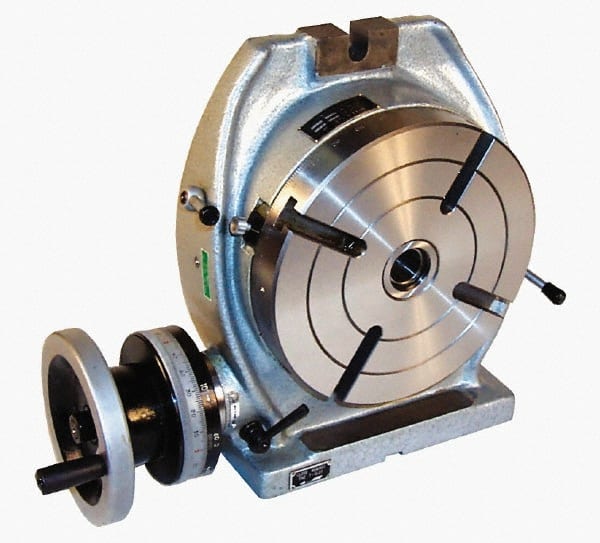
The vertical & horizontal rotary table, one of the main accessories of the milling machine, is a precision work positioning device. This machine is widely used in metalworking, enabling the operator to drill or cut work at exact intervals around a fixed axis.
It can be mounted "flat," with the table rotating around a vertical axis, in the same plane as the cutter of a vertical milling machine. Or, mounted the rotary table on its end (or mount it "flat" on a 90° angle plate) so that it rotates about a horizontal axis. In this configuration, a tail stock can also be used, thus holding the workpiece "between centers."
It"s not difficult for you to adjust the rotary table milling machine. What you should do is to adjust the handle to the position where you want because the precise scale is marked on the dial.
Except for the 5.9""(150 mm) rotary machine table, we also offer you four locating blocks. The center can be corrected quickly and accurately by the Key guide block.

You’ll use your CNC milling coordinate system fundamentals everywhere, not just for one particular CNC machine. Even the latest CNC machines are the same at their core: they use an X, Y, and Z-axis to define the coordinate space inside the machine, and a tool (sometimes an endmill, sometimes an extruder, sometimes a laser beam) moves around that space. The technology might change, but the fundamentals remain essentially the same. In this article, we’ll be covering the basics of the CNC coordinate system, including the Cartesian coordinate system, work coordinate system (WCS), and offsets.
Additive machines build a part from the bottom up. There’s no question about where the piece starts on the build plate. However, something like a milling machine has to subtract material away from an external object. To do this, the machine needs to understand the position of the stock in physical space. If only it were as simple as shoving a block of metal into your CNC and pressing go.
Things start to get complicated when adding in a variety of milling tools. Each bit has a different length, which changes the distance between the spindle datum and the workpiece. That origin point you just set for a 1″ long endmill isn’t going to work for a 3″ long drill.
You can think of the coordinate system as how CNC machines understand 3D space. Without a coordinate system, your CNC would have absolutely no way of knowing:
Put all of this together, and you have a CNC machine that can cut various sides of a workpiece in the XY plane and at various depths along the Z axis. Whether it’s a milling machine, router, or laser, they all use this fundamental movement system.
The movement of your CNC along the coordinate system is always based on how your tool moves, not the table. For example, increasing the X coordinate value moves the table left, but looking from the perspective of the tool, it’s moving right along a workpiece.
If reading that left you more confused than before, don’t worry. Understanding the difference between the movement of your tool and table is easier to show than explain with words. Check out the video below from Robert Cowan to see this in action:
Under the hood, the process can vary from machine to machine. For some machines there is a physical limit switch that signals the controller that a machine has reached an axis limit. On some machines there’s an entire servo system in place that makes this entire process incredibly fluid and precise. A machine controller sends a signal through a circuit board to a servo motor, which connects to each machine axis. The servo motor rotates a ball screw that’s attached to the table on your CNC machine, making it move.
A CNC machine will use a work offset to determine the difference in distance between your WCS and its own home position. These offsets are stored in the machine’s controller and can typically be accessed in an offset table.
Since one of the vice jaws is fixed, we can use this jaw to determine a repeatable Y-axis origin, finding this location with the help of an edge finder or probe.
Now the part has to be flipped over to work on the other side. Since we just flipped the part 180 degrees, the outer contour was symmetric, and the previous X and Y offsets were repeatable, the WCS will not change. We are also using the same tool so that the same Z offset can be used.
This is a simple example; the part is square, the XY origin was repeatable for all three setups, and even the Z origin only changed once. But the thought process of workholding alignment, repeatability, and accuracy of previous features is important, and you’ll find yourself going through those basic steps again and again.
Three-purpose lathe chuck / universal with a set of external OJS and internal IJS jaws and a key Average w: 100 mm Clamping: M3(screws only from the front) Other dimensions and parameters - see attached PDF Accuracy, throwing - see enclosed PDF Other sets of internal and external jaws can be purchased - see related products. The chuck has a lubricator directly on the front of the chuck, we recommend the lubricant oil KV 100 during machining without rinsing or Vaseline Gleit 520HP 520TS / MOGUL CALSUL 2 WR when rinsing. The chuck is delivered in a paper box with a Czech manual. Including sets of Allen screws for clamping only from the front(type M3). Suitable for grinders, dividers, turntables, etc.
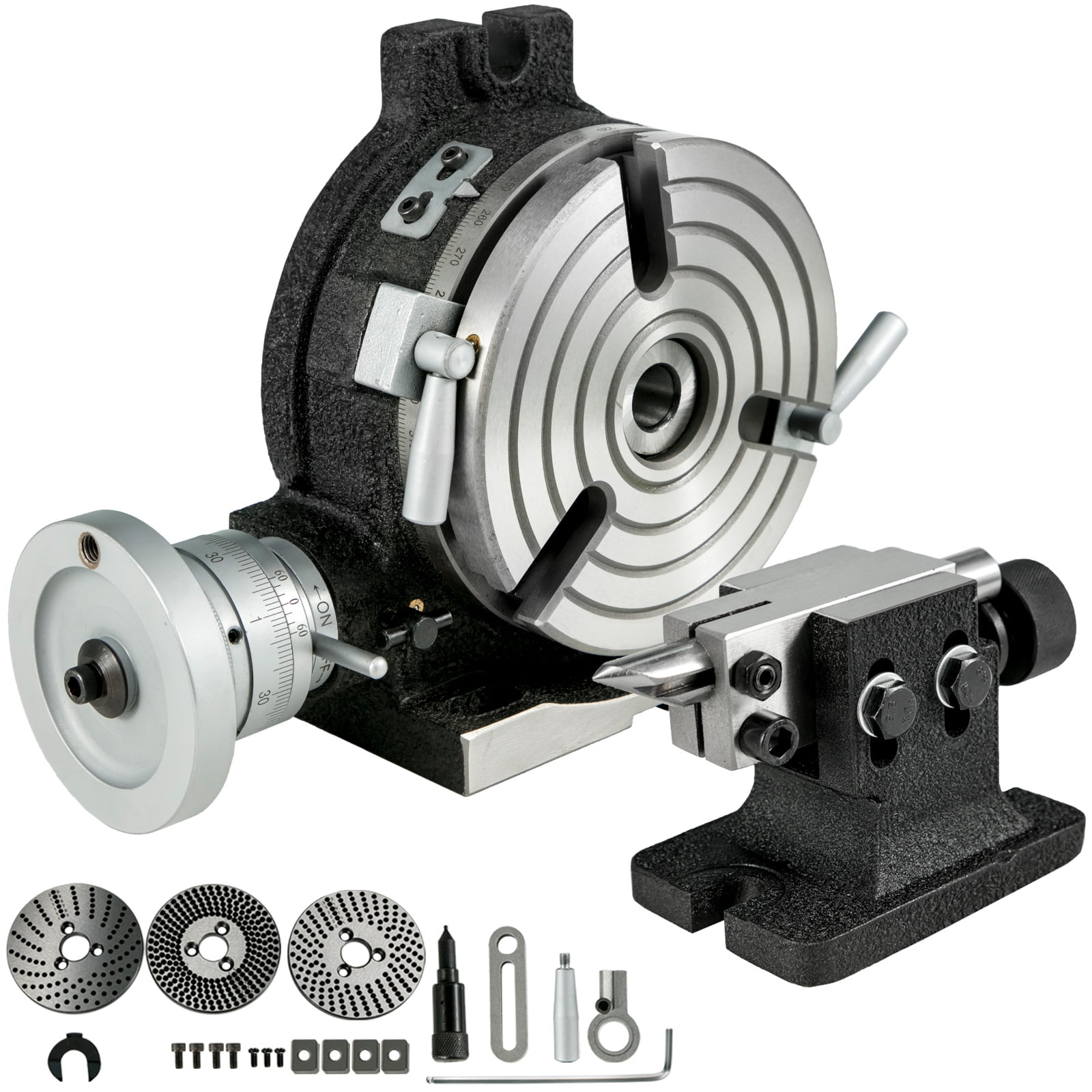
The possibilities are endless with the SB1364 6" Rotary Table as you repeatedly cut circular slots, radius corners and drill any pattern of holes. It was designed with a MT#2 Morse taper and can be mounted vertically or horizontally depending on your needs.
The handwheel scales, degree and vernier, can be easily aligned with each other and adjusted for easy viewing. The vernier scale is used to measure table rotation by ten arc seconds at a time.
When fully tightened, the table locks keep the table from rotating to reduce the strain on the gears during operation. The backlash adjustment lock secures the backlash adjustment ring in place. The backlash adjustment ring lever controls the backlash adjustment ring for adjusting the backlash between the gears.
The manual was written by our U.S. based Technical Documentation Department and is packed with useful information. The complete and easy to read manual provides full instructions on how to assemble and maintain your rotary table.


 8613371530291