
mounting chuck to rotary table made in china

This website is using a security service to protect itself from online attacks. The action you just performed triggered the security solution. There are several actions that could trigger this block including submitting a certain word or phrase, a SQL command or malformed data.

You are right about getting the morse taper correct! that has been in my thoughts about this set up! I have thought about it for a while and I think would want to make this as short as I could, also I am not real concerned about getting the morse taper fit really tight just a good snug fit, and have a flange like you do and just drill about 3 holes in that flange for some allen flat heads and drill and tap the rotary table so it can be bolted down and no chance of moving! so basically the tapered hole in the rotary table would be to line up the adapter not really do any holding the flange and the flat head allens would be bolted down to the table! best set up would be just so the tapered shaft morse #2 would fit so the flange could pull it into the taper flush with the rotary table top! would take a bit of fitting to get it just right but can be done! to me that would be the ideal way to get it made, if the morse taper was not so hard to turn you could machine it until it fit just right but it would have to be indiacted in to run true and they are a pain in the @#%[email protected]#% to make with the right angle on the compound! for this set up it would be better if the hole in the rorary table was not tapered it would make the whole job an easy one! but if the table is needed for vertical work the tapered hole is handy!

I have bought two Chinese made chucks and with the exception that one has to remove sharp edges in the jaw and other parts of the chuck, they have done OK.
In the case of a rotary table the backing plate must be centered to the pilot hole in the table and the registry step in the plate has to be concentric to the the pin that you will install in the backing plate.

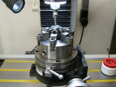
I"ve had a few requests for muzzle brakes and flash hiders. I had this little tilting 4" table with a 3" chuck. It did work, but I had to take things so slow to avoid chatter or completely knocking the work loose. Stronger, bigger, heavier iron was the answer. Turning the key is a little stiff, but I haven"t cleaned or lubed it yet. I don"t see why this won"t serve the purpose just fine. Will I be building Pratt & Witney rocket engine parts with it ? No. Will it get me within a couple of thou if I take my time setting everything up just right, and keep it there while I do my cuts ? No doubt. The chuck and adapter plate are $240 USD shipped within the US. All said and done, including import fees, a little more shipping (I suspect), currency exchange...the usual stuff they saddle us poor Canadian guys with....LOL.... all said and done, it was $341.07 Canadian pesos, delivered to my door step. Still cheaper than any 8" chuck that I can buy here by half.
Is there any relatively easy way I can fit a 3-jaw chuck concentrically to a rotary table when the chuck only has mounting holes from the rear. Or do I have to go out and buy one with mounting holes from the front?
If your chuck has a Myford backplate you can buy an adaptor which fits your rotary table and has a Myford threaded nose to accept the chuck. Alternatively you can do what I have done and make an adaptor which fits the MT in the table and has a threaded nose to suit whatever is on the chuck backplate. If you do this you must use a drawbar to secure the adaptor in the table taper - it is a very short taper.
I have got a three-slot table so could make a backplate to fit the table, mounting with T nuts and bolts and bolting the chuck to this backplate first.
To make it more versatile (because I want to use other tooling as well) I am making an arbour threaded with the spindle nose uppermost and an MT taper to fit the table (mine"s MT2) so that I can screw any of my chucks to the arbour.
If its not a threaded chuck then turn a circular plate about 25mm larger dia than the chuck, counterbore or countersink for the chuck mounting screws and then mill 3 or 4 slots into the edge depending on the number of slots in your table and use these with tee nuts, studs etc to hold it to your table just like the Chronos ones
I have a 3/8 thick 5" dia. "sub plate" that has a short male register turned on one side to locate in the RT and a female register on the top side that accepts a plug to register the chuck concentrically. The chuck was drilled for 6mm capheads that hold it to the sub plate (from beneath), the sub plate is then held to RT with 6mm capheads into tee nuts in the RT slots
I should add that the 3 jaw is the Myford type with internal thread and register which makes the above relatively straight forward. This will of course be more of a problem if the chuck has a conventional backplate.
In the near future I"m intending to make a low profile indexing table and intend to drill right through the chuck for the hold down bolts. This will eliminate the sub plate.
I made a threaded nose with a 100mm dia flange with slots to take bolts that go into T nuts in my 6" rotary table, I,v tryed to keep things as low as possible, but with 8" chucks I have minimal room with the jacobs chuck in the mill, so I find use for short drills ect.Ian S C
Use this to line your the chuck’s own back plate and your new adaptor and spot through the retaining screws to hold the chuck to the adaptor. Use counter sunk screws.
On my home made table I made a small table the same diameter as the mini-lathe chuck (80mm) with a deep groove all round so you can get at the mounting screws. It means its a bit higher than usual by about 1", but I can also put my 7" faceplate on it.
I suppose you could make a short locating plug, MT one end, and some sort of boss to fit the chuck at the other end. Then hold the chuck down using Tee nuts and long bolts/ clamps on the outside of the chuck. This would give you maximum vertical headroom. Drill/ bore a hole thro the plug in case you need to mount a longer workpiece in the chuck. Bit crude, but it would work !
I go away for a couple of days and there are a myriad of really helpful replies. Thank you so much! I will be able to make a suitable chuck fitting for my RT this weekend.
For what its worth my chuck is a Chinese one with a shallow recess for fitting to a backplate. Unfortunately, no Myford or Boxford here. So I"ll be using the ideas based on the thick plate twixt RT and Chuck.
It is indeed interesting that none of the usual tool suppliers has filled the requirement for an RT with an integral, concentric, low-height chuck over a wide range of sizes....
I have the adaptor from Chronos for the Boxford lathe and mount it to my rotary table Only issue I have is that it often unwinds itself so I need to come up with some idea to fix it when trying to machine a large flywheel as the lathe will not take the size of flywheel. Any body have any ideas?? Newbie Mike
Could make some brake shoe devices to bolt into the rotary table slots and come into firm contact with the body of the chuck. Need one in each slot to ensure force is symmetrical so no tendency for the chuck to be pushed out of true. I"d use softwood shoes on an L shaped bracket with a projection on the base of the L so that tightening the bolt pushes the shoe into contact. Use a scrap of alloy sheet under the projection so it doesn"t mark the table.
Simpler way would be to get one of the long jubilee clips used to hold smoke deflectors on chimneys, central heating pressure vessels (and probably lots of other things) to clamp simple L brackets to the chuck which could similarly be bolder to the table. 3 mm alloy would probably work, bends easily and will take up the chuck diameter when the clip is done up. Maybe two clips for extra security.
a week or so ago I posted a bit on my rotary table fitted with a chuck. I made a base-plate (photo below, right) between chuck and table- The base plate bolts to the table and is larger in diameter than the table and chuck. I drilled the chuck through so that it bolts onto the base plate from the front of the chuck.
Surrounding the chuck is a larger ring that also bolts to the base plate ( below left) and has four screws through the side that impinge on the chuck. Backing off slightly on the three chuck bolts allows the work piece to be nicely centred using the 4 side screws, and then tighten up the chuck bolts.
Forgive the repeat of the photos of the previous post - I have not managed to work out how to give a link to just a specific section post in the forum...
I have drilled 4 M10 holes in my RT allowing me to bolt down a 4 jaw chuck. They were carefully located to make the chuck body as near concentric as possible. But the way I look at it is that I would never put something round in the 3 jaw in the lathe and expect it to run true - I always try to plan to get all the concentric things turned at one setting. If something has to run true it goes in the 4 jaw on the lathe. So why is it different on a rotary table?
Thought proceess might be best started with the RT purchase - four T-slots, not three. I mistakenly bought a 4 jaw self centering chuck for mine and regretted it. I will change it for an independent four jaw next time I need to remove it. The independent chuck does not even need to be mounted that central - how many rotary tables are spun at high speed!
A baseplate fitted to a three slotted RT, followed by the 4 jaw chuck is better than a self centering chuck. I cringed, every time I have wanted to remove that current chuck, to mount something direct on the RT. It will not be fitted centrally again!

I did a very similar thing with mine, Its a small 4 inch rotary table, and I made an adapter for use with my 3/4-16 chucks, and faceplates that I have standardized on for my small stuff.

I feel for ya. Went through this same issue years ago. They can be pricey lumps of metal for some reason. I"ve read about some OK Chinese stuff & also some horror stories. Its such a crap shoot if you cant see it in person. If it was only clean out casting grit, repack the grease & tweak a bit that would be fine. But if the gears are cut crappy or platen & surfaces are not ground properly then its an irritating boat anchor because difficult to replicate those components. And RT"s are heavy PITA parts to return weight/shipping wise through online vendors sight unseen. Vertex makes pretty good stuff IMO. Just watch out for the tricky label "like Vertex" brands that are creeping in. Dividing plates... useful for sure really depends on what you see yourself making. The only consideration is if you say no now & years later want them, there"s a chance you might not see the correct set, they can have nuances how they mount. Tailstock - again depends on what you are making. Long skinny things in horizontal mode need rotating support just like a lathe but there you could defer or get away with a clone since they are so adjustable. But sometimes the combo kit deals work out to the accessories being not a lot of extra $$, it all depends.

I am used to my other 4-jaw chuck on my lathe having a rather loose fit, but it had been damaged at some point and I made new screws which are not precisely machined.
As I look closer at this chuck, I notice a few things that indicate it may have been repaired. On the back, the yoke pins have small tapped holes with set screws in them, and there are punch marks corresponding to 1, 2, 3, and 4. But the single punch mark corresponds to a "4" on the outer surface of the chuck, while the face is marked "3" which matches the number stamped in the jaw"s slot. Two punch marks are for "1" on the outer surface and "4" on the face, matching the #4 jaw. Three punch marks are for "2" on the outer surface and "1" on the face and matching the jaw. Four punch marks are for "3" on the outer surface and "2" on the face and jaw.
Also, the entire chuck is very clean and the machined surfaces look as if they may have been bead blasted or otherwise treated. Yet the bore has some caked-on substance like old grease and rust. I can"t find any manufacturer markings - just a 160 (mm), 0779, and 85. One of the outer mounting holes seems to have been drilled through part of those stamped numbers, and there is an off-center shallow counterbore on another hole, where I have seen manufacturer insignia on other chucks.

Please refer to the pictures and diagram to be sure the kit will mount to your table. Your rotary table should look similar to the one in the photo- for illustration only, the rotary table is not included with the CNC drive kit.

PO Box, APO/FPO, Afghanistan, Alaska/Hawaii, Albania, Algeria, American Samoa, Andorra, Angola, Armenia, Austria, Azerbaijan Republic, Bangladesh, Belgium, Benin, Bermuda, Bosnia and Herzegovina, Botswana, Burkina Faso, Burundi, Cameroon, Cape Verde Islands, Central African Republic, Central America and Caribbean, Chad, China, Comoros, Cook Islands, Côte d"Ivoire (Ivory Coast), Democratic Republic of the Congo, Denmark, Djibouti, Egypt, Equatorial Guinea, Eritrea, Estonia, Ethiopia, Finland, France, French Polynesia, Gabon Republic, Gambia, Georgia, Ghana, Greece, Greenland, Guam, Guinea, Guinea-Bissau, Hungary, Iceland, India, Iraq, Ireland, Italy, Jordan, Kazakhstan, Kenya, Kiribati, Kyrgyzstan, Laos, Latvia, Lebanon, Lesotho, Liberia, Libya, Liechtenstein, Lithuania, Luxembourg, Madagascar, Malawi, Mali, Malta, Marshall Islands, Mauritania, Mauritius, Mayotte, Mexico, Micronesia, Mongolia, Montenegro, Morocco, Mozambique, Namibia, Nauru, Nepal, New Caledonia, Niger, Nigeria, Niue, Pakistan, Palau, Papua New Guinea, Portugal, Republic of Croatia, Republic of the Congo, Reunion, Russian Federation, Rwanda, Saint Helena, Saint Pierre and Miquelon, Senegal, Seychelles, Sierra Leone, Solomon Islands, Somalia, South America, South Korea, Spain, Swaziland, Switzerland, Tajikistan, Tanzania, Togo, Tonga, Tunisia, Turkey, Turkmenistan, Tuvalu, US Protectorates, Uganda, Ukraine, Uzbekistan, Vanuatu, Vatican City State, Vietnam, Wallis and Futuna, Western Sahara, Western Samoa, Yemen, Zambia, Zimbabwe

The Vertex is different from the others ... you have to buy a separate lathe-style chuck with an MT2 or MT3 arbor sticking out the back of the chuck. The main part has a MT2 or MT3 hole, and the body rotates on a horizontal axis to tilt. You don"t have to use the usual lathe-type chuck on it. For small work you can use a Jacobs chuck with arbor. I don"t think you can do rotation about 2 axes, just one; but I could be wrong. I have seen one at the tool store I go to and they have still not sold it after a couple of years so perhaps it is not as useful as I think but it sure does look nice.
As for the term "hinge", I made that up. The one I am thinking of is still called a rotary table; there are two parts ... the rotary table, and then the base. The two are connected on one side by the hinges (just two tabs with holes, a rod, and the horizontal hole in the base that the rod goes through). The tab parts fit over the edges of the base and the rod slides through the tab holes and the horizontal hole in the base.
Even with a rotary table that is not hinged, you can mount it vertically and in that position you might call it a dividing head because you can usually buy a tailstock for it, and, for certain ones the dividing plates.
I forgot to tell you that I had this. Again, I knew I would need one eventually, so I bought one even before I met you !! Have only started to use it.

This website is using a security service to protect itself from online attacks. The action you just performed triggered the security solution. There are several actions that could trigger this block including submitting a certain word or phrase, a SQL command or malformed data.


 8613371530291