
using rotary table on milling machine supplier

... conventional machines. Axis movement is performed by high quality servomotors, increasing accuracy and efficiency. Simple handling and reliability make this model very popular.
... approximation of the motorized table, automatic advance of the rod, square guides on Y / Z axes, tilt front / rear of 45 ° and centralized lubrication as standard.
... stainless steel structure, these machines feature multi-station rotary tables for optimized processing time, and automatically manage the unwinding and winding of the cloths; the moving ...
With DirectIndustry you can: Find the product, subcontractor or service provider you need | Find a nearby distributor or reseller| Contact the manufacturer to get a quote or a price | Examine product characteristics and technical specifications for major brands | View PDF catalogues and other online documentation
The TR160 5 Axis Rotary Tables, manufactured by Haas, consist of dual axis Trunnion rotary table that is capable of tilting up to 160 mm. It also has a scale assessment ...
The TR210 is HAAS"S rotary table developed and configured to be integrated with HAAS"S mills 4th and 5th axis drivers to provide complete and optimum operation. It has a diameter of 210 mm made from trunnion ...
... space with high load capacity. The individual rotary tables are equipped with Harmonic Drive units, which ensure high moment load capacities and high concentricity and axial runout accuracies.
The work table is graduated 360 degrees around its circumference and is driven by a precision Worm and Gear providing a 90:1 reduction ratio. One turn of the Handle moves the Table through 4 degrees. ...
... Tilt-Yaw (A/B) two-axis rotary assembly provides high-speed machining capabilities for complex 3D part geometries. The precision-aligned system allows accurate positioning on a hemispherical surface. ...
... ) MDR two-axis rotary assembly provides high-speed machining capabilities for complex 3D part geometries. The precision-aligned system allows accurate positioning on a hemispherical surface. Uses cost-effective ...
... ) MDR two-axis rotary assembly provides high-speed machining capabilities for complex 3D part geometries. The precision-aligned system allows accurate positioning on a hemispherical surface. Uses cost-effective ...
Our FÖRSTER swivel welding tables offer maximum working comfort for all-round welding of complex assemblies. Ideal for all tasks due to a variable arrangement of our patented T-slot system.
The hydrostatic rotary tables from ZOLLERN impress with their durability and a high concentricity and axial runout accuracy. Thanks to the ZOLLERN bearing clearance compensator, the optimal pocket pressure ...
... the table is the rotation, the user may require the rotary table for drilling operations and milling. Using the servo drives in conjunction with the machine CNC control ...
With DirectIndustry you can: Find the product, subcontractor or service provider you need | Find a nearby distributor or reseller| Contact the manufacturer to get a quote or a price | Examine product characteristics and technical specifications for major brands | View PDF catalogues and other online documentation
The rotary table is simply a round flat surface that can be rotated. What makes it interesting is that the table is driven round using a worm and wormwheel arrangement. This means that if a workpiece is mounted on the table it can be machined as it rotates.
On a rotary table the ratio between the worm and wheel is often about 40:1 on a small table but increases with the size of the table. For example a 360mm (12-inch) table might have a ratio of 120:1.
Rotary tables are calibrated round the edge in degrees and have a handle which turns the worm and which, in turn, will rotate the table by 360º divided by the ratio of the worm and wheel. For example, a 360mm (12-inch) table with a 120:1 worm and wheel will rotate by 3º per turn. The handle mechanism has a rotating dial and a Vernier so the angle, on a larger rotary table, can be measured to a few minutes.
Naturally any worm and wheel arrangement on a rotary table is likely to have some backlash. Sometimes this can be compensated for by adjusting the distance between the worm and wheel. Usually any backlash can be ignored if the movement, when machining, is always one way.
The same mechanism can sometimes be used to disengage the worm from the wormwheel. This is useful on large rotary tables because it enables the user to turn the wheel quickly to get from one position to another. (It is not possible to machine the workpiece whilst doing this.)
All rotary tables have a hole in the middle of the table. This is usually a parallel-sided hole but some, especially on smaller rotary tables it is tapered.
This hole can be used to take spigots that can be used to align the rotary table or align the workpiece on the table. Sometimes it is possible to fit a bolt through this hole using various spacers, washers, etc to hold the workpiece on the rotary table.
It is possible the get a device that has a taper on one end that is designed to fit the taper as found on some small rotary tables. The other end has a thread that is designed to fit the backplate as used on the chucks used on some lathes.
All rotary tables can be mounted in the horizontal position on the milling table. Some are designed so they can also be mounted vertically without any other hardware.
Most have slots in the base so they can be bolted to the milling table. Some do not but have a flange so that they can be clamped to the milling table.
It is possible to buy rotary tables that have the facility to tilt the table built in to them. Some even can be tilted at any angle in either or both of two planes at right angles. But all of this adds significantly to the height and weight of the rotary table.
The usefulness of being able to tilt in two planes is very limited and would probably not justify the space it would take up. But a rotary table that tilts in one plane can be useful. This setup can easily be emulated by fitting a rotary table to a tilting table.
Most rotary tables have some means of locking the table at any particular position. Very often an operation is done whilst the table is being rotated in which case the force of the cutter cancels any backlash. However when an operation such as drilling is being done at a particular point then the table should be locked.
Very often a cut needs to be made between two points at the ends of a particular arc. Usually it is not possible to make the cut in one go but several passes are needed. In this case it is useful to have two stops so each cut will start and stop at exactly the same points. This is very useful for preventing mistakes.
The fig. shows a stop. The movable part clamps to the top of the rotary table’s table. Two of these are needed. The fixed part has been fitted to the hole normally used for the locking mechanism as shown in the previous fig.
It will be noticed that the same hole on the rotary table is used for both locking and for a stop. But, of course, in practice, it will, at any one time, only be needed for one function or the other.
For milling any particular workpiece on a rotary table one has to allow for the space around the workpiece for the clamps used to hold it. For example a 200mm rotary table might hold a workpiece that had to have 120mm hole cut into it. It will be shown later how to effectively extend the diameter of a rotary table. It is often desirable to get the largest rotary table that will fit the milling machine table. However larger rotary tables can be very heavy.
With a large milling machine the practical limit is probably the largest you can lift safely. It is possible to have some sort of lifting gear but this all takes time. It is worth looking carefully before buying because for a given diameter, different makes or different methods of construction can cause a rotary table to vary dramatically in weight.
There will usually be enough space between to milling table and the cutting tool to fit a rotary table to do any required job. But there is always the height of the workpiece to consider. If other devices are to be mounted on the rotary table then the space rapidly disappears.
Most rotary table are set up as shown above to be rotated by a certain number of degrees. This is done using the calibrations on the table marked in degrees.
If it is necessary, when using a rotary table to divide a circle into a number of equal sectors then it is necessary to divide 360º by the number of sectors required. On a small rotary table, the table might only be calibrated to 5°. On larger ones they might be calibrated to individual degrees round the edge but will have a vernier arrangement on the handle so they can be set to a certain number of minutes. This gives us the angle between the sectors. Each time we move from one sector to the next we have to add the angle per sector onto the last angle. For any but the simplest numbers, the chances of getting this right are not great.
It is possible to have dividing plates fitted to a rotating table, as shown above, but this is unusual. But since dividing plates are always fitted to dividing heads these will be covered under dividing heads.
It is quite common to need to be able to divide a circle into so many parts. With dividing plates this is easy and is covered elsewhere. for a rotary table using just degrees and minutes a circle can be divided by one of the following methods.
A calculate the angle in your head or using a calculator for the origin for each sector and write them down. Most simple calculators will give decimal angles whereas the rotary table is marked in degrees and minutes.
C Use tables showing the angles for each position for a circle divided up to 200 sectors can be found in Appendix C. These are in degrees and minutes.
D use the table for the first 200 sectors that can be found in “Tables for [the] Cooke Optical Dividing Head” published by Cooke, Troughton and Simms.
Here is what I like to use as a test indicator holder. It can allow you to indicate in something without removing the tool. They have several options for in spindle or spindle nose clamp styles. eBay does have some cheaper import version that work ok, but once you have use the Indicol quality, there is a big difference. You will need to buy the test indicator as a seperate item. There are a lot on the market. I have had my B&S(brown and Sharp) "Best Test" indicator for almost 30 years and one repair. Reasonably rugged and very reliable. Sticky indicators like some imports do you no good. If the needle pointer does not move, it is inviting a false sense of security.
The whole premise is to use the spindle bearings to sweep an indicator around the surface you wish to align it to. It is much easier in concert with a DRO, but dials will get you there too.
As long as you do not move the table, you could indicate the part in by knocking it around until it sets in the same location. You could also spin the table itself and knock the part around to find its true center on the rotation of the table bearings. Some of the cheaper import rotary tables may not have the spindle bore as reliably on center as what they will rotate on their shaft.
The same indicator setup can check for spindle tram also. This will need to be checked periodically anyways to verify the spindle is perpendicular to the table surface. If the head is tilted and you indicate in a feature. If the point that it is indicated in at changes in height, so to will the location of the features you intend to machine in relation to that reference. The longer the tool bit is away from the indicated origin, the further off location the new feature will be. Where this is seen is when the part is indicated in at one level, but the distance between the spindle and work needs more room for the tool. So when the table drops away, the point of origin in relation the spindle center (being at an angle) is out lost in space now. The new feature(s) can be found way off location even though the table was moved correctly during the setup. Best advice is to keep this in mind if the knee or head will be moved in a Z axis, always check the tram first. Especially after a crash, broken cutter or large unexpected force at the cutter.
The same holds true for vises parallel to an axis. For critical work, always check the solid jaw for axis alignment. If it is at an angle and a feature is indicated in on one end of the jaws, it might not be at the other end. More or less exponentially to the angle it is off over XX distance from the origin.
Main objective here is to use as much of the machines built in geometry to maintain pure geometry on the part as the machines is capable of. A test indicator is the best way to obtain this level of precision.
Having said that, if you have the right attachment you can convert your lathe into a mill - won"t be as rigid nor as flexible but in smaller sizes of task it will get the job done.
A rotary table goes on a milling table, and allows the work to be rotated under control, normally of a worm and wheel. Cutting radial slots and parts of a circle. Depending on the table, there are also adaptors which allow gears to be cut, or specific numbers of holes to be drilled, usually but not always equally spaced. Rotary tables will normally be graduated in degrees (and division thereof) of arc.
Another benefit of using a vertical milling machine is the relative ease with which you can drill series of holes in straight lines - or if you have one with a digital readout (DRO), holes in a complex arrangement as well. This is also perfectly possible without the DRO, but it really does make it a lot easier. So a milling machine can also double up as a very posh pedestal drill...
And as I hinted above, milling machines do come in two basic varieties - horizontal and vertical. Most people regard vertical milling machines as being generally more useful, and they are generally easier to set up, but horizontal machines also have their uses. Some machines are regarded as "universal" - they can run as either.
I would concur with Steve about the use of a vertical mill, with a DRO, as a drilling machine. I hardly ever use my drilling machine; using the vertical mill is just so much more convenient and accurate. And it makes drilling bolt patterns a breeze with the DRO. No more spotting through to one component from another; just drill the two patterns separately and they should fit together.
Generally the horizontal mill is seen as a production machine tool, and is less flexible than a vertical mill. However, for a given size a horizontal mill will most likely be heavier, more rigid and more powerful than a vertical mill. So, if you need to move a lot of metal a horizontal mill will do the job much faster.
By the way, a universal mill is not one that has both vertical and horizontal capability. It specifically refers to a horizontal mill that has a swivelling table so that, with the aid of a suitable dividing head, it can be used to machine spiral features, such as flutes on a custom cutter, or a helical gear.
They can divide up lengths into divisions. So if you want to drill four (or 44) holes in a 6" length, give it the parameters and it will do the divison for you and provide the co-ordinates for each hole automatically.
They can divide up circles, so it can be a dividing head - tell it the number of holes radius or diameter, start position and it will give you the co-ordinates.
You can feed in a number of points, co-ordinated from a start point. So if you have to drill a cylinder block, a valve chest and chest cover, on say 2 identical cylinders, which is 6 sets of holes all to match - you can make a jig, or you can put your DRO into the right mode and it wil remember all the hole positions, and you just wind down to zero for each
There are other functions like milling in 3d, milling squares and variations on squares, and I"m sure some I haven"t mentioned and most of us wouldn"t think of or need
Wonderful things, and save a lot of number crunching and repositioning of work and counting feedscrew turns. Great aid to accuracy and sanity. Some say they are not essential for milling, and thats true, since lots of people have done a lot of very good work without, but they are a seriously nice addition.
Must admit having bought a rotary table I have only used it a couple of times to mill slots in a collet (120 degrees apart) and flats on a bolt head (60 degrees apart)
1. Should the graduations on the hand wheel align with the marks on the rotating table, by which I mean when the hand wheel has a mark in line with the reference mark on the body the line for the degree on the rotary table is not aligned with the reference mark on the body. If "yes" is there any way of adjusting this?
By the way, a universal mill is not one that has both vertical and horizontal capability. It specifically refers to a horizontal mill that has a swivelling table so that, with the aid of a suitable dividing head, it can be used to machine spiral features, such as flutes on a custom cutter, or a helical gear.
But yes, it"s the table that is the universal bit, hence them being correctly referred to as universal table milling machines, rather than just "universal".
Hi Steve, I guess what you ment is that there are horizonal milling machines that also have provisons with the suitable attachments (often an opional extra) to become a vertical milling machine,
I think for the ME vertical milling machines are more vesitile, but horizontal ones do have some avantages. In the ideal workshop you would have both, but of course budget and space prevail.
Rotary tables can do all the things that have been said, and like mgj says can do things you haven"t even though of untill a job crops up and you scheme a way of doing it. Many of them are designed to be used in the horizontal plain and the vertical plain. A small one can be used on the cross slide of your lathe in the vertical plain for instance and be used for drilling holes in discs or cylinder blocks ect. especially if it has the option of fitting dividing plates to it.
Wasn"t there a well made little machine that used to be advertised Sharp was it. That had horizontal and vertical spindles.It called itself a universal, but didn"t have the pivoting table.
Pivoting table type mills would reallly need to be on the big side, simply because the dividing heads with the spiralling attachment driven off the feedscrew tends to be a bit large. You can get away without turning the table a long as the lead on the spiral is not too great, and more so if the thread is rounded. The result would be an approximation, but for most purposes it would be good enough. bit academic though - not a facility most would use. For most of us, it would only be used for setting up say ftapered fluted columns, and there are other ways of doing that.
Scheming a way of doing it -I have a 13" 6DP gear to cut for the 4" Little Samson. Someone does some 80mm thick cast iron slab, so a chunk of that will become a raising block for the dividing head which isn"t designed for that size of work, but its the principle.
For Colin a dividing head is another sort of rotary table. RT tend to be optimised for continuous movement- curved slots and surfaces. Dividing heads are optimised to provide definite stops for things like gear teeth or cutting hexagons or any other gons for that matter. (Of course with adaptors each can be either, but I think thats a fair description.)
waht is for sure, you need some means of dividing fairly ealry on in your career. You don"t need a full blown dividing head with all its worm gears etc, but some form of simple adaptor for basic indexing which gives the common divisions - 2,4,6,8,12 holes becomes very useful very quickly.
Hi, I don"t know what makes a milling machine truely universal. I have a brocher that my old company I used to work for chucked out when they got rid of a Parkson 1NA Universal Miller, made by J. Parkson & Son (Shipley) Ltd,.
Looking through this brocher it seems it really was universal. As well as having a table that swiveled at 45 degree each side of centre, it had various add on bits of kit. Some of the kit included vertical spindle milling component, slotting component, cam milling component, feed reducing equipment, power driven rotary table, a universal dividing head which could be used in conjunction with universal milling components styles A & B which could cut helical gears and worms without the table being swiveled. The two milling components could also cut racks held in a jig. The universal deviding head could be used in conjuction with the feed reducing equipment to cut scew theads or spirals of short, single or mulitiple lead, or similar work.
I"m in the same boat as you. For my traction engine I need to cut 6DP gears with ODs of 10.833" and 11.833", and 5DP final drive gears that are 14.8" OD. I"ve got 16" maximum from table to spindle centreline on my horizontal mill. So the 6DP gears will go under, with the use of 1" riser blocks for the dividing head and tailstock.
However, whichever way you look at it, the final drive gears will not go under the spindle with a cutter in place. If I had the plain version of the mill rather than the universal, I would have 19" from table to spindle, and no problem.
I"m contemplating three options. One, use the rotary table with the gear in the same plane as the table. Fortunately the gears have 72 teeth, so 5 degrees per tooth for simplicity. Two, similar to one, but use the dividing head with the spindle vertical. Three, make an undercutting attachment as per the picture:
By the way, a universal mill is not one that has both vertical and horizontal capability. It specifically refers to a horizontal mill that has a swivelling table so that, with the aid of a suitable dividing head, it can be used to machine spiral features, such as flutes on a custom cutter, or a helical gear.
Could the Swiss Aciera mill on the cover of MEW 171 be an example of your definition? However, it appears that some dyslexia has crept in and the machine is labelled as an Aceria both on the cover and in Roger Trewinnard"s Re-furbishing article commencing on page 40. I could be hopelessly incorrect but lathes.co.uk does not list Aceria.
Hi Steve, I guess what you ment is that there are horizonal milling machines that also have provisons with the suitable attachments (often an opional extra) to become a vertical milling machine,
We haven"t developed the concept fully anyway. For Colin"s benefit we could also mention that there are different types of vertical mill, certainly in terms of turret, knee, round column vs Dovetail, CNC and all sorts of other details, I"m sure. Once you have your head around the basic principles of why milling machines are a good idea, then the scope of the subject is definitely the next thing to consider, isn"t it?
As for the "good idea to have both" thing - well, how could I not agree? I"m very slowly restoring a Tom Senior M1 to its former state of glory (or something along those lines), and it has the knuckle head as well, so I"ll have just that.
With a vertical mill I have 2 extra bits of space. I have a lot more height, but also I can put the dividing head to one side of the spinde CL, so I have the space around the circle to give me room.
I"ll cut on the Y axis moving the work front to back. But that means I have to hang a bit of the dividing head over the edge of the table. Since the DH has a 5" centre height, I can use the raising block as a mount
When I did the 3" engines final drive on a GHT VDH and a Dore Westbury, - that was about 8" dia and much more than a VDH was ever intended for. Again I cut on the Y axis, but hung the whole gear over the edge of the table. Used a C clamp to lock it, so the clamp and table took the force of the cut , and the VDH did the indexing.
Will a scale in degrees around the edge of the table automatically line up with the scale on the handwheel. No - unless you hav some kind of resettable collar on the handwheel. In fact the scale round the edge, I don"t think I have ever used.
The handwheel - all depends on the ratio between the worm and wheel. so you have degees, and minutes which are 60ths of a degree, and probalby a vernier reading typically to 2 or 4 seconds of arc which are 60ths of a minute. Normally off the calculator you will get an answer in decimals of a degree which you will have to convert.
So if you get an answer of say 7.46 deg. .46x60 = 27.6 minutes. The remainder you convert as well. so .6x60 = 36 seconds exactly. So 7.46 deg = 4 deg 27min 36 sec. I wish they would calibrate the scales decimally!
I got two of my 6DP involute cutters, and all of the required 5DP cutters, from a surplus store in America via Ebay. That left me still needing a 6DP No.2 cutter. Personally I haven"t found any of the usual UK advertisers to be particularly helpful. After a fruitless trawl around every stand at last years" Midlands ME show that looked like it might know what an involute cutter might be, I finally bought a new 6DP No.2 cutter from Victor Machinery Exchange in New York. It was listed as an "import" which almost certainly means it was made in China. Total cost including shipping, VAT and inport duty was about £100.
Hi John, sorry I"d forgot you asked about the graduations on the handwheel. I have a Vertex HV6 and I have looked on thier website (below) and it says that the coller is graduated in steps of 1 minute and the vernier scale makes settings down to 10 secounds possible. The ratio of the table is 90:1 and the coller also has 0, 1, 2 and 3 quarted making the 4 degrees that mgj metioned, there is also a 30 midway between each of the above mentioned digits. (see pic below) The vernier has devisions of 60-0-60 in 7 graduations. I have not used this facility myself. but the coller is moveable by loosening the grub screw that can be seen, tuning to the desiered position and then tightening the screw. Once you have a reference mark alined and then turning the table noting how many dregrees, mins and secs you require, it can be done by counting the degrees by the four numbers X the number of rotations of the handwheel, plus the number of minutes on the graduations and then lining up one of the graduation marks to the number of seconds required on the vernier scale. I hope I"ve got that correct and it makes sense, yours may be slightly different, but the proceedure should be much the same.http://www.vertex-tw.com.tw/products/products_list.php?language=_eng&cid=10
Hi, further to my previous post above, my table must be an older version than the one described on the website, as studying it in more detail, the graduations on mine are in 2 minute steps, hence the 30 markings denoting half a degree. The vernier steps are of 20 seconds, therefore setting the table to 10 seconds is approximation by setting the wheel graduations between the appropreate vernier graduations.
My Vertex rotary table (8 inch size) has an adjustable fiducial for the scale on the table part, so you can set the Vernier part on an exact mark and then adjust the fiducial to also be on a mark as well, avoiding ambiguity.
Rotary Milling Table – Horizontal & Vertical System. A rotary table is a precision work positioning device used in metalworking. It enables the operator toread more...
Sector 37D, Gurugram, Haryana 122006, Gurgaon, Dist. Gurugram Nath Tools Company , Garauli Khurd, main Pataudi Rd,, Sector 37D, Gurugram, Haryana 122006, Gurgaon - 122006, Dist. Gurugram, Haryana
- High accuracy, easy reading of all dias clear & functional of all operating elements, sturdy yet good looking practical design. These are widely used for circular cutting, angle cutting, boring and spot facing with aread more...
Under the supervision of experienced and adroit professionals, we offer wide range of Rotary Milling Tables we manufacture an exceptional range of products to our discerning clients. Our entire product range is in adherence with set quality standards and policies and is delivered with adjustable lock facility. Moreover, weread more...
Near Sunrise Bag, Gondal Road, Rajkot Rajlaxmi Estate, Plot No. 27/5, Nr Nirav Complex, Gokuldham Main Road, Samrat Industrial Area, Complex, Near Sunrise Bag, Gondal Road, Rajkot - 360004, Dist. Rajkot, Gujarat
Backed with huge industry experience and market understanding, we are involved in manufacturing a wide variety of Rotary Milling Table Without Indexing for our valued patrons.

Whether you use mills, presses or lathes, machine tools are often only as useful as the accessories that come with them. Take care of repair tasks and add extra functionality with the machine tools accessories at Alibaba.com. If you need new milling machine rotary table or are seeking to replenish your component stocks, our wholesale store is the ideal place to look. We stock accessories for every type of machine tool, with multiple options in most cases. So add resilience to your operations and be ready for any production challenge with the machine tools accessories in our store.
Machine tools come in all shapes and sizes, and so do the accessories that make them tick. For instance, CNC and manual lathes can be customized with jaw chucks, shanks, woodworking knives, drill chucks, rotary chucks, clamps, and turning tools. Add brushes and sanding discs, and turn your machine tool into a multi-purpose machining center. Add a range of cutting tools to milling machines, pick the right drum sanders for your drills, or add a lathe dog to make turning much easier. There are accessories for hydraulic presses, add-ons like drag chains, and many other machine tools accessories. And if you need replacement milling machine rotary table, Alibaba has everything you need.
Our machine tools catalog is packed with accessories. Search the listings for your preferred tool and zero in on accessories that can enhance its functionality. From control handles to tool holders, thread holders and saw blades, the whole panorama of machine tools accessories is here and ready to order. There"s no better way to add extra stocks and renovate machinery when the time comes. When new milling machine rotary table are required, head to the Alibaba wholesale store and give your machinery a new lease of life.
This website is using a security service to protect itself from online attacks. The action you just performed triggered the security solution. There are several actions that could trigger this block including submitting a certain word or phrase, a SQL command or malformed data.

This website is using a security service to protect itself from online attacks. The action you just performed triggered the security solution. There are several actions that could trigger this block including submitting a certain word or phrase, a SQL command or malformed data.
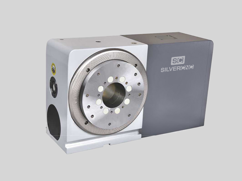
A CNC rotary table is the precision positioning accessory that can provide a reliable 4th axis or even 5th axis for modern machining centers. Utilizing a computer-controlled rotary table can turn the original 3-axis machine tools into 5-axis CNC machines, expanding the accuracy as well as decreasing the costs while performing complex machining operations at one time.
A CNC rotary table is the precision positioning accessory that can provide reliable 4 or even 5 axis cutting operation capabilities for modern machining centers. Utilizing it can turn the original 3-axis machine tools into 5-axis CNC machines, expanding the accuracy as well as decreasing the costs while performing complex machining operations.
Rotary tables typically have rigid frames and coatings, and also excellent torque capacity, which makes the small device flexible and effective for a wide variety of turning, milling, drilling, and more metalworking operations. The easy setup and seamless interface allow the operators to easily add the rotary table to fit their 4-axis or 5-axis applications. .
The working principle is similar to the basic rotary tables, which is to support the workpiece by accurately rotating the workpieces on the axis in order to locate the parts for high precision tooling. Under rapid rotation, which is driven by CNC instructions, the cutting tools of larger machine tools or machining centers can remove the material and add the feature to the products at exact intervals. On rotary tables, there are vertical and horizontal axes for various tools to perform these high-performance metalworks. To enhance the accuracy and flexibility, there are models that employ additional dividing plates and come with additonal material handling mechanisms and features.
Since 4-axis and 5-axis machining is increasingly popular today, adding the CNC rotary table as the 4th axis is an ideal solution to easily open up more complex machining options at a lower cost. Due to the arrangement, they are widely also called the 4th or 5th axis or tilt rotary. The 4th axis, which is the rotational operational direction, is added to the original three linear axes which are known as X-axis, Y-axis, Z-axis. In some cases, there are two rotational axes add to the original 3-axis machining center, achieving utmost accuracy as well as effective multiple face cutting to reach the difficult area on the surface. Rotary tables are usually mounted parallel to the ground or the bed, with the platter rotating around the vertical axis, for example with the most common vertical milling machine combination. Sometimes the machining application requires an alternative setup with the table mountet on its end so that it rotates around the horizontlal axis. Often, a tailstock is used in this configuration. Virtually all models today come with a clamping kit to mount it onto the bed of your machine tool.
The function of the high precision rotary table is also to rotate the workpiece so the cutting tool can create the contour we desired out of the workpiece. However, a rotary table with higher precision has the ability to achieve great accuracy just as its name implies. There is also a major misconception between the resolution and the accuracy.
A common example is that if a digital readout displays to four decimal places, then the high precision rotary table must also be capable of achieving the accuracy to that same value. Even though for higher accuracy to be achieved, the resolution has to also be high, but there is no guarantee that the accuracy is going to be high. The accuracy is the concept which is the difference between the actual position and the position measured by a reference measurement device. The feedback mechanism such as the rotary encoder, and the drive mechanism can influence the accuracy of the advanced rotary table.
A CNC rotary table can provide great rigidity for stable machining operations. It consists of the worktable where the metal parts are held, the rigid bearing that withstands the forces and loads during the rotation, the solid base which is used for attaching the rotary table to the machining center or other equipment, the motor, and the CNC system.
The worktable is the tooling surface where the workpieces are machined after accurate positioning. The worm gearing is the core mechanism of the table, which mesh with the steel worm which is submerged in the lubricants. Both the rigid bearings and the worm gears have large diameters. Excellent concentricity is the key to smooth operation, durability, and most importantly, accuracy. Driven by a computer and electric motor, the worktable can position the materials at exact intervals. For more flexible or critical operations, dividing plates can be added to this component.
A CNC system regulates the simultaneous 4-axis motion of the rotary table. The instructions are programmed and transmitted via CAD software, reducing the time for adjustment and monitoring by human workers.
The type and size of the electric motors utilized in can define the router accuracy as well as the efficiency of the device. Servo motor and stepper motor are two typical types that can be divided into more subtypes. The servo motor uses a closed looping variable circuit, the circuit will constantly run to keep the function. The brushes must be replaced every 2000 hours of operation in the servo motor. Compared to stepper motors, servo motors are more efficient in power consumption. On the other hand, the stepper motor has a simpler setup which are the wires that are attached to the driver. The bearing of the stepper motor is the only wearing component. However, the stepper motor consumes a great amount of energy.
There are currently several different types and models available in the industries. Each of them possess its own traits and abilities. Let us take a look at the most common ones other than standard three axis tables
The 4 axis CNC rotary table will process the workpieces by holding them in the same position while the cutting tool performs along the XYZ plane to trim away the unwanted material. In general, a 4 axis model is very versatile equipment that can be used for several different industrial processes such as engraving curved surfaces, continuous cutting, and intermittent cutting. Besides, people can also add other devices such as cam machining, blade machining, and helical grooves to the 4 axes rotary table. Such a feature is simply impossible to achieve with the machining center which has only 3 axes.
Besides the 4 axis ones, there are also 5 axis models. They have the ability to allow the workpiece to be processed automatically from five sides at one time. people usually utilized the 5 axes rotary table in the industries such as the automobile, the aerospace, and the boating industries. The reason that the 5 axes rotary table is commonly used in heavy industries is that the 5 axis machining is an important technique to be used when the components need better intricacy and quick precision. All of these have more than three axes are called the multi-axis rotary table.
The installation method of the precision rotary table can be horizontal, vertical or inverted. When installed horizontally, the workbench surface is in a flat, vertical and horizontal position. When installed vertically, a rotary table is installed so that the surface of it can run up and down. In the reverse layout, itcan be rotated upside down in a horizontal position. The location of the drive of the rotary table can depend on the mount. The drive can be placed on the back, below, on the top or on the side.
When mounted horizontally, the spinning table top drive is positioned above the table floor. When the rotary table is horizontally placed, the side-mounted drive is located on the edge of the table board. The driving mechanism of the rotary table may be manual, electrical, pneumatic, hydraulic or non-driven. For manual revolving workbenches, release the workbenches and manually spin the workbenches with the crank.
Workpieces are gathered and machined through PC and fully programmed instructions. The 5-axis simultaneous operations will be measurably more reliable than products machined via different technologies. Also, the setup is simple and provides an indistinguishable process in every production cycle, the consistency of the quality of the metal products can be ensured under critical control and precision cutting.
Since the metalwork is driven by software, the preferred frameworks can be programmed and adapted by the rotary table. Saving both the cost and the room makes themis the ideal solution for potential users who don’t want to install larger equipment and new machines which may take up a great room for a wide variety of machining applications.
Another benefit is the utmost movements can be completed precisiely and faster. There are more favorable positions, operation angles as well as accessible machining that can be achieved through the technology. The complex operations are suitable for blade, helical grooves production, and other applications required to add complex features or require critical inspection in machining processes like the manufacturing of aerospace, automotive parts, and scientific equipment.
Addding a rotational table saves time because the extra finishing jobs or other sub-operations can also be performed at one time in the machining center.
A rotary table can be used in many applications including manufacturing, inspection, and assembly. Indicators are used, for example, for assembly, manufacturing, and bottling equipment. They typically use a single item in workspaces or move relatively small layouts of items around stations for sequential work or assembly.
In automated assembly machines, the rotary tables implementation is widespread, and choosing the right mechanism is important for both improving efficiency and reducing the cost of this vital component. This guide discusses two common devices for rotating indexing and offers guidance on the right range. There are several ways to get mass mobilization when it comes to the development of rotary indexing tables. Regardless of whether the load or load in centuries of thousands of kgm2 is incredibly light. When choosing a robust rotary index solution that will match or meet your standards, there are several factors to take into account when spinning, elevating, or pushing.
When determining the influencing factors on the postitioning accuracy, the first thing to look at is the mechanical properties of the table itself. A rotary table contains six degrees of freedom. Each of these movements increases the total risk of positioning errors. Usually, a rotary table is driven by a worm gear, which is connected to the motor through a rotary encoder on the back. The position of the table can be determined by the number of pulses transmitted from the encoder to the control device.
The four main sources of error due to the semi-closed position loop are geometric errors, thermal deformation, elasticity, and wear. The sum of these errors is called angular positioning error. To greatly reduce the angular positioning error, the ideal position for installing the angle encoder is on the rotating shaft under test. The angle encoder is installed under the rotary table, and the rotary encoder is installed under the rear motor, the position loop is now considered a closed-loop system.
Precision is a relative term. About a quarter of an inch is great and will meet the accuracy of its application. Others, for example, require micron-level accuracy in measuring and indexing devices. Then, some applications fall within these extreme ranges.
The misunderstanding is that you may have used an inaccurate indexing device and made it accurate by introducing a pin or wedge locking device. These devices increase the complexity and cycle time of use, and when they are used together with a high-precision positioning device, they may cause damage and reduce accuracy.
In the actual test, by selecting specific components, motion index drive, servo rotary indexer, the measurement accuracy is as high as 5-6 microns. These are not the results approved by Motion Index Drives, but the results of customer certification. When starting and stopping large amounts of data, it is important to know how fast it takes to stop the application with large amounts of data.
In a less rigid environment or the presence of higher recoil, a faster start and stop will bring many control problems. When moving masses (whether rotating mass or linear mass), starting and stopping in a system with a backlash of several arc minutes will cause a lot of back and forth movement in the gear system. The result is a force that is difficult or even impossible to calculate. In addition, when the gear head is used in rotating applications, the farther the mass is from the center of rotation, the greater the backlash. In applications with very slow deceleration times, recoil may not be a problem.
Backlash in the positioning process is a big issue – when it comes to the beginning and stopping volumes, it"s crucial to know how quickly you need to avoid the mass of your rotary indexing table applications. In a less rigid system or where there is an increased backlash, quicker start-ups and stops can cause a lot of control issues. When shifting a mass, whether rotary or linear, starting and stopping in a system with several minutes of backlash arc will create a lot of back-and-forth motion within the gearing system. The effect is a power that can be difficult and probably hard to quantify. In comparison, as the gear head is used for rotational applications, the more the mass is from the axis of rotation, the further the backlash is magnified.
The backlash may not be a concern in systems where deceleration times are incredibly long. In the case of cam indexers, there is " Zero Backlash." The cam indexer and rotary table dynamics give an incredibly rigid, highly regulated framework. A modern cam indexer system is capable of withstanding short cycle times with stop times in milliseconds.
So you want to get the smart manufacturing going but are not sure of what to look for in rotary tables. The information provided in this section may be able to help. The primary factor is to determine the mass snapshot of inactivity. This is often overlooked when measuring a rotary table for the machine.
Another significant factor is the size of the workpiece being rotated, including how big it is and how substantial it is. You want your rotary tables to be large enough to handle enormous pieces. This is where tilling rotary tables may become handy so that the pieces can be handled without causing interior harm. They allow the quickening and decelerating of machining at appropriate rates.
The last factor is accuracy, the applications for which, for instance, pivoting a gigantic part to allow welding highlights on it where the individual stop positions can be genuinely free. On an additional note, when choosing direct drive rotary tables, factors that you should consider when selecting a rotary table for your CNC machinery include accuracy, backlash, mass moment of inertia, acceleration and deceleration, speed, and environment.
Indexing system use is commonly possible in automatic assembly machines and the right process is important for both performance maximization and cost reduction.
Cam indexers are an omnipresent tool used for several decades for rotary indexing tables. They are suitable for applications that often index the same angle and need a high degree of accuracy at a relatively low cost. To place the load, a cam indexer uses a mechanical cam. A math curve is pushed onto the cam and provides incredibly smooth and repeatable movement.
Another popular alternative is a fully programmable rotary index table. A rotary table is advantageous in two different situations. Firstly, a versatile movement pattern is important. An example is if two components are running on one computer, each of which requires different index patterns. For incredibly fast placement accompanied by a long period, another condition that matches the servo pointer is. The need to accelerate the camshaft while the cam indexing mechanism was operating before starting the output movement reduced the on-demand cam indexer. Acceleration of the camshaft is possible, but there is a delay before the movement begins. There are realistic restrictions.
With an indexing table, the output rotates as soon as the servo starts moving. This is not difficult for a continuous cam indexer or a zero-backlash servo indexer, but it can also be difficult for an on-demand cam indexer. For applications with high-speed servo indexing, smooth movements are crucial. A zero-backlash preloaded reducer can achieve this. The ideal alternative for correct positioning with high dynamic response would be the zero-backlash reel drive system.
Application parameters, like a moment of inertia, indexing angle, indexing period, and residence time, are required for each indexer style. The rotary indexing table for the application should also be sized correctly by a reputable manufacturer.

Our dealer and auctioneer members offer the most extensive selection of used machinery in the world, with thousands of machines available in warehouses and plants across the globe.
Manufacturer of standard and custom 360 degree linear rotary tables for scanning, assembly, testing and production applications. Features vary depending upon model, including worm and gear drive design with central rotating ball bearings, manual and motorized operation, hollow spindles, four mounting holes, accessible adjustment clamps and graduated knobs. Accessories such as rotating table adapter plates, brackets, platform shelves, thumbscrew locks, alternative knobs, limit switches provided. Manually operated rotary motion turntables also available. Suitable for mounting and rotation of test specimens, cameras, transducers, sensors, mirrors and other components. Stock items and repair services are offered. One year warranty. Made in the USA.

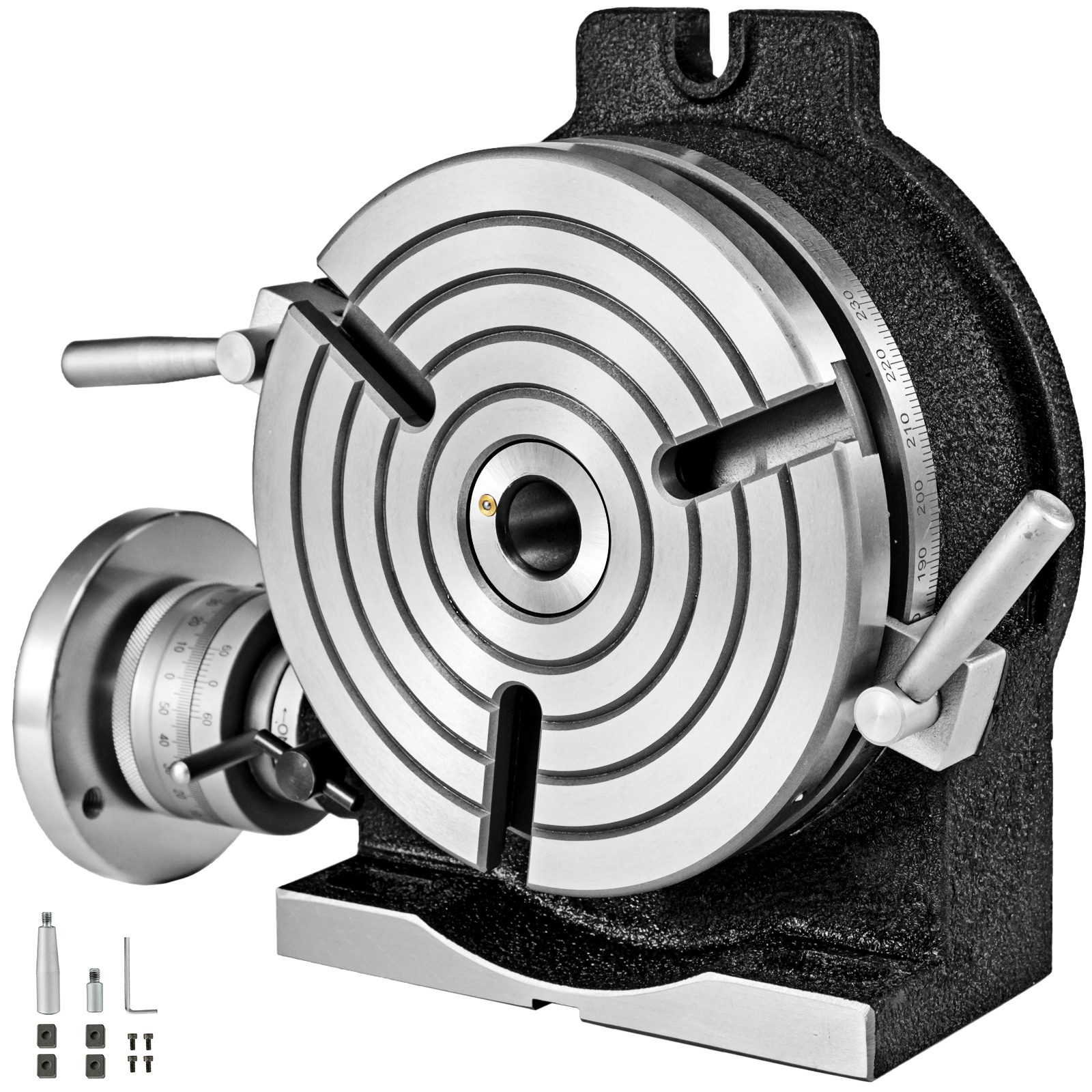
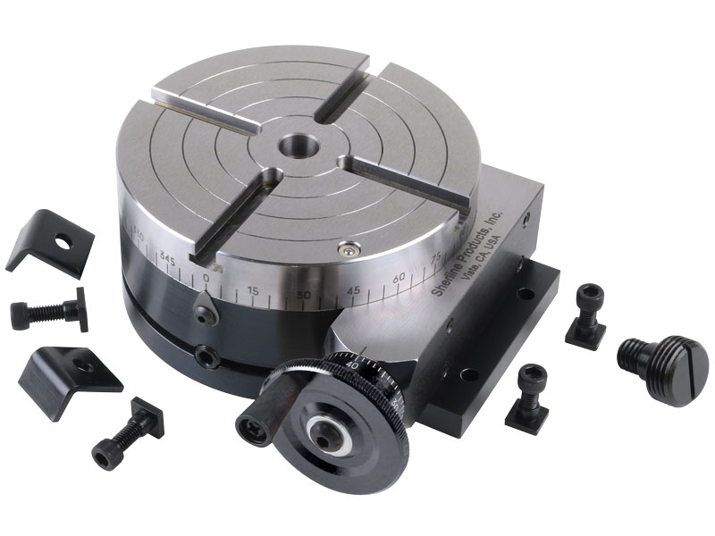
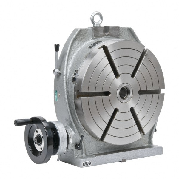
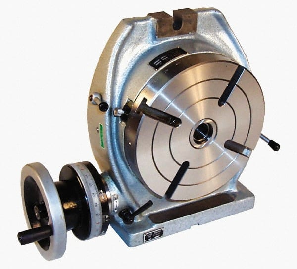
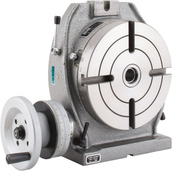
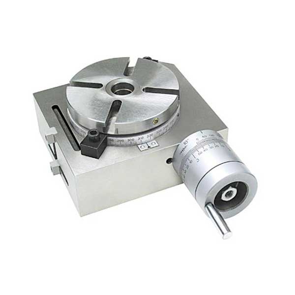
A rotary table is a precision work positioning device used in metalworking. It enables the operator to drill or cut work at exact intervals around a fixed (usually horizontal or vertical) axis. Some rotary tables allow the use of index plates for indexing operations, and some can also be fitted with dividing plates that enable regular work positioning at divisions for which indexing plates are not available. A rotary fixture used in this fashion is more appropriately called a dividing head (indexing head).
The table shown is a manually operated type. Powered tables under the control of CNC machines are now available, and provide a fourth axis to CNC milling machines. Rotary tables are made with a solid base, which has provision for clamping onto another table or fixture. The actual table is a precision-machined disc to which the work piece is clamped (T slots are generally provided for this purpose). This disc can rotate freely, for indexing, or under the control of a worm (handwheel), with the worm wheel portion being made part of the actual table. High precision tables are driven by backlash compensating duplex worms.
The ratio between worm and table is generally 40:1, 72:1 or 90:1 but may be any ratio that can be easily divided exactly into 360°. This is for ease of use when indexing plates are available. A graduated dial and, often, a vernier scale enable the operator to position the table, and thus the work affixed to it with great accuracy.
Rotary tables are most commonly mounted "flat", with the table rotating around a vertical axis, in the same plane as the cutter of a vertical milling machine. An alternate setup is to mount the rotary table on its end (or mount it "flat" on a 90° angle plate), so that it rotates about a horizontal axis. In this configuration a tailstock can also be used, thus holding the workpiece "between centers."
With the table mounted on a secondary table, the workpiece is accurately centered on the rotary table"s axis, which in turn is centered on the cutting tool"s axis. All three axes are thus coaxial. From this point, the secondary table can be offset in either the X or Y direction to set the cutter the desired distance from the workpiece"s center. This allows concentric machining operations on the workpiece. Placing the workpiece eccentrically a set distance from the center permits more complex curves to be cut. As with other setups on a vertical mill, the milling operation can be either drilling a series of concentric, and possibly equidistant holes, or face or end milling either circular or semicircular shapes and contours.
To create large-diameter holes, via milling in a circular toolpath, on small milling machines that don"t have the power to drive large twist drills (>0.500"/>13 mm)
with the addition of a compound table on top of the rotary table, the user can move the center of rotation to anywhere on the part being cut. This enables an arc to be cut at any place on the part.
Additionally, if converted to stepper motor operation, with a CNC milling machine and a tailstock, a rotary table allows many parts to be made on a mill that otherwise would require a lathe.
Rotary tables have many applications, including being used in the manufacture and inspection process of important elements in aerospace, automation and scientific industries. The use of rotary tables stretches as far as the film and animation industry, being used to obtain accuracy and precision in filming and photography.


 8613371530291