
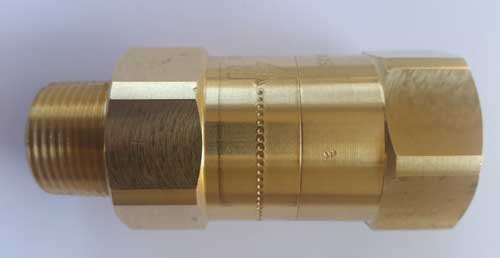
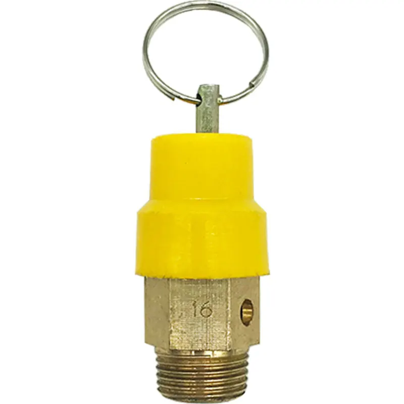
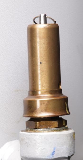
compressor safety valve free sample
An OSHA COMPRESSED AIR SAFETY SHUT-OFF VALVES should be placed immediately after the air control shut off valve and before the hose on a compressor, and after each discharge port that a hose is connected to.
Before starting the compressor the air control valve should be closed completely. When the compressor unloads, open the air shut off control valve very slowly. Full port ball valves tend to work better than gate or butterfly type valves.
The air shut off control valve must be fully open for the OSHA COMPRESSED AIR SAFETY SHUT-OFF VALVES to work. Some portable air compressor manufacturers recommend start-up with the air control valve slightly open. In this case you may have to close the valve and reopen it slowly to the full open position, or wait for the safety shut-off valve to reset itself.
If the OSHA COMPRESSED AIR SAFETY SHUT-OFF VALVES fails to operate despite meeting all condi-tions, check the hose line for obstructions or a hose mender restricting normal air flow.
• Turn on air supply slowly (to avoid tripping OSHA safety valve). Prior to fully reaching operation conditions, the OSHA COMPRESSED AIR SAFETY SHUT-OFF VALVES should suddenly activate and stop air flow.
• If the OSHA COMPRESSED AIR SAFETY SHUT-OFF VALVE is not activated the unit should be disconnected and the lower flow range OSHA COMPRESSED AIR SAFETY SHUT-OFF VALVES should be used. This means you need to use a different valve with a lower scfm range.
• At temperatures below 40°F ensure that OSHA COMPRESSED AIR SAFETY SHUT-OFF VALVES are not subject to icy conditions which may prevent proper functioning.
You may not worry often, if at all, about whether or not your air compressor is running safely. And you really don’t have to, because compressor manufacturers do. From the pressure rating on the air storage tank to emergency stop buttons, air compressors are designed with safety in mind.
But that doesn’t mean you should never think about your compressor’s safety features. In most cases, they need to be inspected regularly to make sure they’re working properly. One key safety feature that should be inspected regularly is the air pressure relief valve (PRV), sometimes called a safety relief valve.
The pressure relief valve is a safety valve that protects the compressor component that it’s attached to from being exposed to a pressure above its rated maximum operating pressure. This rating, called the maximum working pressure (MWP), is the pressure that the vessel has been certified to continuously operate at safely.
So when a compressor is running at or below its maximum working pressure—in other words, when it’s running “normally”—the relief valve doesn’t do anything.
However, when the air pressure inside a compressor exceeds its MWP, the pressure relief valve will activate to “blow off” the excessive pressure within the compressor. Without a relief valve, the storage tank could rupture from the excessive pressure, damaging the compressor itself, possibly other property near it, and even causing injuries (or worse) to anyone standing nearby.
Before we can talk about how the air pressure relief valve works, we first need to look at how air pressure inside a compressor is managed when everything is running normally.
Under normal circumstances, the air pressure in a compressor is controlled by a pressure switch in an electro/mechanical control system or, in the case of an electronic controller, a pressure transducer and controller settings. When the cut-out set pressure for the pressure switch is reached, the compressor will stop compressing air (unload) until the cut-in set pressure is reached, at which time it will start compressing air again (load). If the pressure switch fails, the compressor would not be able to start compressing air again, or potentially worse, not be able to stop. Most compressors also have a high-pressure safety switch that should stop the compressor if the pressure exceeds the unload set point.
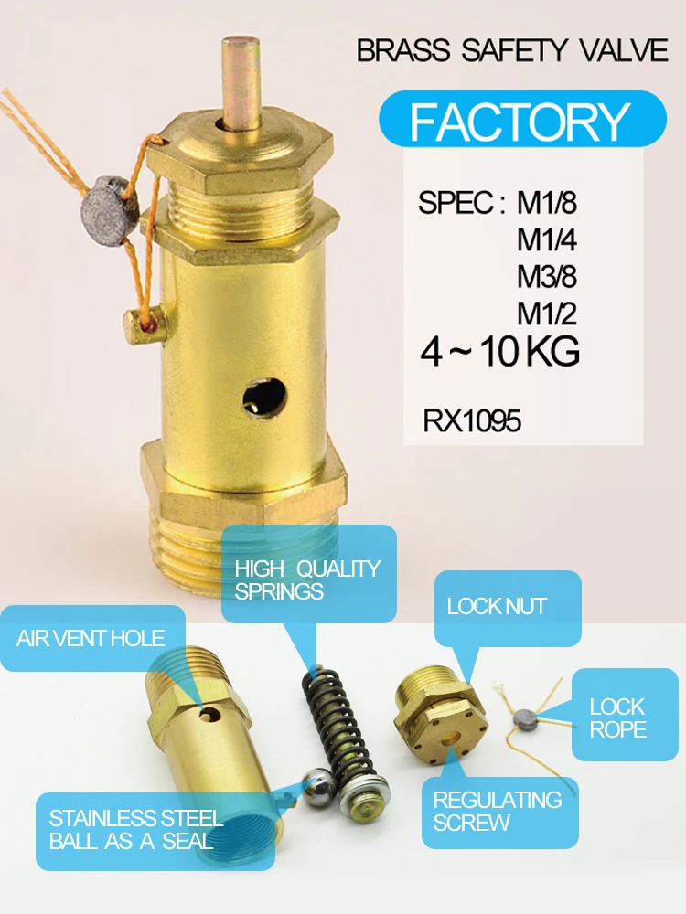
A pressure relief valve is a straightforward safety backup to the pressure switch and high-pressure switch, or the controller set points, should any of these components fail with the compressor running. The safety relief valve is set above the high-pressure safety switch and generally at or below the vessel’s maximum operating pressure. Inside the valve is a spring, and the pressure created by the spring’s tension keeps the valve closed under normal operating conditions. However, as the air pressure increases in pressure vessels (like the storage tank), it eventually exceeds the rated pressure of the relief valve, causing the relief valve to open and the excess pressure to be “blown off” to the atmosphere.
If the pressure relief valve fails open, air will continually vent to the atmosphere, preventing the air stream from becoming fully pressurized. The compressor should be shut down and the relief valve replaced before the compressor is restarted. The open relief valve will likely cause a loss of production and possible danger to personnel as a result of the flow of high-pressure air with flying debris and an unsafe sound level.
A pressure relief valve failing closed presents a potentially more dangerous situation. As noted earlier, the relief valve exists to allow excessive pressure to be “blown off” so that the air pressure inside the compressor’s pressure vessels don’t exceed their rated specifications. If the valve fails closed, this pressure venting can’t happen. Unless compressed air demand matches the compressed air supply, the pressure inside the compressor will continue to build. Eventually, the pressure increase would cause the storage tank to rupture, damaging the compressor and possibly causing additional damage and injury to property and people nearby.
If the relief valve is opening because the air pressure in the compressor has exceeded the valve’s pressure set point, that means the valve is working and doing what it was designed to do. But because this indicates the MWP of the compressor has been exceeded, the condition that’s causing excessive pressure should be diagnosed and corrected.
If the relief valve opening wasn’t caused by excessive pressure inside the compressor, then the valve is most likely “failing open”. Most likely, this is because the valve has become “soft” over time, i.e. the valve spring is providing less counterpressure, so it’s opening at a lower pressure than it should.
Whether the valve opened because of excessive pressure in the compressor or because the valve is failing, you should have your local air compressor distributor inspect your compressor before running it again for two reasons:
First, your distributor can determine whether the valve opened due to a failing relief valve or excessive compressors pressure and perform any needed maintenance or service to get your compressor running efficiently and safely again.
Second, regardless of why the pressure relief valve opened, replacing it may be recommended to ensure safe compressor operation, depending on the valve manufacturer. (Replacement is recommended for Sullair compressors.)
Important: Running the compressor after the relief valve has opened, regardless of the reason why it opened, can put both your property at risk of damage and people at risk of injury (or worse). While this may be obvious if the compressor is building up excess pressure, it also applies if the valve failed open. As noted above, even a valve that fails open poses some risk, and next time it could fail closed.
Given how critical a working air pressure relief valve is to the safe and efficient operation of your air compressor, you may wonder whether you need to do any regular inspecting or testing of the valve to make sure it is working. Because this can vary by manufacturer, you should consult your owner’s manual or contact your local air compressor distributor for frequency and type of inspection needed. For most Sullair compressors, inspection for damage or leakage is recommended, but testing is not recommended, as doing so may compromise the valve’s performance.
However, one thing you should do is schedule regular maintenance with your local air compressor distributor. As part of regular maintenance, a service technician can inspect the PRV and let you know it’s at an age or in a condition at which the manufacturer recommends replacement. Also, problems with the compressor’s performance, e.g. not reaching normal operating pressure, may help the service technician identify a failing relief valve after ruling out other possible causes.
When a pressure vessel like a receiver, sump tank or other storage vessel is purchased separately from the compressor, it may not be supplied with a pressure relief valve. To ensure its safe operation, you should add a PRV.
When selecting a PRV to add to the pressure vessel, you must choose a valve with a pressure set point set at or below the maximum working pressure of the vessel. You will find the MWP (and other useful information) on a tag welded to the pressure vessel. Also, flow capacity of the PRV must meet or exceed the total compressed air supplied to the vessel.
For example, if you have two compressors with capacities of 500 and 750 cfm (14.2 and 21.2 m³/min), and a pressure vessel with a maximum working pressure of 200 psi (13.8 bar), the minimum settings for a pressure relief valve would be 1250 cfm (35.4 m³/min) and a set point 200 psi (13.8 bar) or less.
Finally, when attaching the valve to the vessel, the porting must not be reduced to a size less than the size of the inlet port of the pressure relief valve.
Because the pressure relief valve is critical to the safe operation of your compressed air system, if you’re not sure how to select the correct PRV and properly and safely add it to the pressure vessel, contact your local air compressor distributor. They have the experience and expertise to ensure that the PRV is sized and installed correctly.
In addition, we may disclose information collected from and about you as follows: (1) you expressly request or authorize us to do so ; (2) we believe the information is needed to comply with the law (for example, to comply with a search warrant, subpoena or court order), respond to a government request, enforce an agreement we have with you, or to protect our rights, property or safety, or the rights, property or safety of our employees or others ; (3) the information is provided to our agents, third parties or service providers who perform functions on our behalf ; (4) to address emergencies or acts of God ; (5) in anticipation of and in the course of an actual or potential sale, reorganization, consolidation, merger, or amalgamation of all or part of our business or operations in which case your information may be provided to the purchaser or resulting entity ; or (6) to address disputes, claims, or to persons holding a legal or beneficial interest.

A safety valve must always be sized and able to vent any source of steam so that the pressure within the protected apparatus cannot exceed the maximum allowable accumulated pressure (MAAP). This not only means that the valve has to be positioned correctly, but that it is also correctly set. The safety valve must then also be sized correctly, enabling it to pass the required amount of steam at the required pressure under all possible fault conditions.
Once the type of safety valve has been established, along with its set pressure and its position in the system, it is necessary to calculate the required discharge capacity of the valve. Once this is known, the required orifice area and nominal size can be determined using the manufacturer’s specifications.
In order to establish the maximum capacity required, the potential flow through all the relevant branches, upstream of the valve, need to be considered.
In applications where there is more than one possible flow path, the sizing of the safety valve becomes more complicated, as there may be a number of alternative methods of determining its size. Where more than one potential flow path exists, the following alternatives should be considered:
This choice is determined by the risk of two or more devices failing simultaneously. If there is the slightest chance that this may occur, the valve must be sized to allow the combined flows of the failed devices to be discharged. However, where the risk is negligible, cost advantages may dictate that the valve should only be sized on the highest fault flow. The choice of method ultimately lies with the company responsible for insuring the plant.
For example, consider the pressure vessel and automatic pump-trap (APT) system as shown in Figure 9.4.1. The unlikely situation is that both the APT and pressure reducing valve (PRV ‘A’) could fail simultaneously. The discharge capacity of safety valve ‘A’ would either be the fault load of the largest PRV, or alternatively, the combined fault load of both the APT and PRV ‘A’.
This document recommends that where multiple flow paths exist, any relevant safety valve should, at all times, be sized on the possibility that relevant upstream pressure control valves may fail simultaneously.
The supply pressure of this system (Figure 9.4.2) is limited by an upstream safety valve with a set pressure of 11.6 bar g. The fault flow through the PRV can be determined using the steam mass flow equation (Equation 3.21.2):
Once the fault load has been determined, it is usually sufficient to size the safety valve using the manufacturer’s capacity charts. A typical example of a capacity chart is shown in Figure 9.4.3. By knowing the required set pressure and discharge capacity, it is possible to select a suitable nominal size. In this example, the set pressure is 4 bar g and the fault flow is 953 kg/h. A DN32/50 safety valve is required with a capacity of 1 284 kg/h.
Coefficients of discharge are specific to any particular safety valve range and will be approved by the manufacturer. If the valve is independently approved, it is given a ‘certified coefficient of discharge’.
This figure is often derated by further multiplying it by a safety factor 0.9, to give a derated coefficient of discharge. Derated coefficient of discharge is termed Kdr= Kd x 0.9
Critical and sub-critical flow - the flow of gas or vapour through an orifice, such as the flow area of a safety valve, increases as the downstream pressure is decreased. This holds true until the critical pressure is reached, and critical flow is achieved. At this point, any further decrease in the downstream pressure will not result in any further increase in flow.
A relationship (called the critical pressure ratio) exists between the critical pressure and the actual relieving pressure, and, for gases flowing through safety valves, is shown by Equation 9.4.2.
Overpressure - Before sizing, the design overpressure of the valve must be established. It is not permitted to calculate the capacity of the valve at a lower overpressure than that at which the coefficient of discharge was established. It is however, permitted to use a higher overpressure (see Table 9.2.1, Module 9.2, for typical overpressure values). For DIN type full lift (Vollhub) valves, the design lift must be achieved at 5% overpressure, but for sizing purposes, an overpressure value of 10% may be used.
For liquid applications, the overpressure is 10% according to AD-Merkblatt A2, DIN 3320, TRD 421 and ASME, but for non-certified ASME valves, it is quite common for a figure of 25% to be used.
Two-phase flow - When sizing safety valves for boiling liquids (e.g. hot water) consideration must be given to vaporisation (flashing) during discharge. It is assumed that the medium is in liquid state when the safety valve is closed and that, when the safety valve opens, part of the liquid vaporises due to the drop in pressure through the safety valve. The resulting flow is referred to as two-phase flow.
The required flow area has to be calculated for the liquid and vapour components of the discharged fluid. The sum of these two areas is then used to select the appropriate orifice size from the chosen valve range. (see Example 9.4.3)

In order to ensure that the maximum allowable accumulation pressure of any system or apparatus protected by a safety valve is never exceeded, careful consideration of the safety valve’s position in the system has to be made. As there is such a wide range of applications, there is no absolute rule as to where the valve should be positioned and therefore, every application needs to be treated separately.
A common steam application for a safety valve is to protect process equipment supplied from a pressure reducing station. Two possible arrangements are shown in Figure 9.3.3.
The safety valve can be fitted within the pressure reducing station itself, that is, before the downstream stop valve, as in Figure 9.3.3 (a), or further downstream, nearer the apparatus as in Figure 9.3.3 (b). Fitting the safety valve before the downstream stop valve has the following advantages:
• The safety valve can be tested in-line by shutting down the downstream stop valve without the chance of downstream apparatus being over pressurised, should the safety valve fail under test.
• When setting the PRV under no-load conditions, the operation of the safety valve can be observed, as this condition is most likely to cause ‘simmer’. If this should occur, the PRV pressure can be adjusted to below the safety valve reseat pressure.
Indeed, a separate safety valve may have to be fitted on the inlet to each downstream piece of apparatus, when the PRV supplies several such pieces of apparatus.
• If supplying one piece of apparatus, which has a MAWP pressure less than the PRV supply pressure, the apparatus must be fitted with a safety valve, preferably close-coupled to its steam inlet connection.
• If a PRV is supplying more than one apparatus and the MAWP of any item is less than the PRV supply pressure, either the PRV station must be fitted with a safety valve set at the lowest possible MAWP of the connected apparatus, or each item of affected apparatus must be fitted with a safety valve.
• The safety valve must be located so that the pressure cannot accumulate in the apparatus viaanother route, for example, from a separate steam line or a bypass line.
It could be argued that every installation deserves special consideration when it comes to safety, but the following applications and situations are a little unusual and worth considering:
• Fire - Any pressure vessel should be protected from overpressure in the event of fire. Although a safety valve mounted for operational protection may also offer protection under fire conditions,such cases require special consideration, which is beyond the scope of this text.
• Exothermic applications - These must be fitted with a safety valve close-coupled to the apparatus steam inlet or the body direct. No alternative applies.
• Safety valves used as warning devices - Sometimes, safety valves are fitted to systems as warning devices. They are not required to relieve fault loads but to warn of pressures increasing above normal working pressures for operational reasons only. In these instances, safety valves are set at the warning pressure and only need to be of minimum size. If there is any danger of systems fitted with such a safety valve exceeding their maximum allowable working pressure, they must be protected by additional safety valves in the usual way.
In order to illustrate the importance of the positioning of a safety valve, consider an automatic pump trap (see Block 14) used to remove condensate from a heating vessel. The automatic pump trap (APT), incorporates a mechanical type pump, which uses the motive force of steam to pump the condensate through the return system. The position of the safety valve will depend on the MAWP of the APT and its required motive inlet pressure.
This arrangement is suitable if the pump-trap motive pressure is less than 1.6 bar g (safety valve set pressure of 2 bar g less 0.3 bar blowdown and a 0.1 bar shut-off margin). Since the MAWP of both the APT and the vessel are greater than the safety valve set pressure, a single safety valve would provide suitable protection for the system.
Here, two separate PRV stations are used each with its own safety valve. If the APT internals failed and steam at 4 bar g passed through the APT and into the vessel, safety valve ‘A’ would relieve this pressure and protect the vessel. Safety valve ‘B’ would not lift as the pressure in the APT is still acceptable and below its set pressure.
It should be noted that safety valve ‘A’ is positioned on the downstream side of the temperature control valve; this is done for both safety and operational reasons:
Operation - There is less chance of safety valve ‘A’ simmering during operation in this position,as the pressure is typically lower after the control valve than before it.
Also, note that if the MAWP of the pump-trap were greater than the pressure upstream of PRV ‘A’, it would be permissible to omit safety valve ‘B’ from the system, but safety valve ‘A’ must be sized to take into account the total fault flow through PRV ‘B’ as well as through PRV ‘A’.
A pharmaceutical factory has twelve jacketed pans on the same production floor, all rated with the same MAWP. Where would the safety valve be positioned?
One solution would be to install a safety valve on the inlet to each pan (Figure 9.3.6). In this instance, each safety valve would have to be sized to pass the entire load, in case the PRV failed open whilst the other eleven pans were shut down.
If additional apparatus with a lower MAWP than the pans (for example, a shell and tube heat exchanger) were to be included in the system, it would be necessary to fit an additional safety valve. This safety valve would be set to an appropriate lower set pressure and sized to pass the fault flow through the temperature control valve (see Figure 9.3.8).
Safety valves and pressure relief valves are crucial for one main reason: safety. This means safety for the plant and equipment as well as safety for plant personnel and the surrounding environment.
Safety valves and pressure relief valves protect vessels, piping systems, and equipment from overpressure, which, if unchecked, can not only damage a system but potentially cause an explosion. Because these valves play such an important role, it’s absolutely essential that the right valve is used every time.
The valve size must correspond to the size of the inlet and discharge piping. The National Board specifies that the both the inlet piping and the discharge piping connected to the valve must be at least as large as the inlet/discharge opening on the valve itself.
The connection types are also important. For example, is the connection male or female? Flanged? All of these factors help determine which valve to use.
The set pressure of the valve must not exceed the maximum allowable working pressure (MAWP) of the boiler or other vessel. What this means is that the valve must open at or below the MAWP of the equipment. In turn, the MAWP of the equipment should be at least 10% greater than the highest expected operating pressure under normal circumstances.
Temperature affects the volume and viscosity of the gas or liquid flowing through the system. Temperature also helps determine the ideal material of construction for the valve. For example, steel valves can handle higher operating temperatures than valves made of either bronze or iron. Both the operating and the relieving temperature must be taken into account.
Back pressure, which may be constant or variable, is pressure on the outlet side of the pressure relief valve as a result of the pressure in the discharge system. It can affect the set pressure of the upstream valve and cause it to pop open repeatedly, which can damage the valve.
For installations with variable back pressure, valves should be selected so that the back pressure doesn’t exceed 10% of the valve set pressure. For installations with high levels of constant back pressure, a bellows-sealed valve or pilot-operated valve may be required.
Different types of service (steam, air, gas, etc.) require different valves. In addition, the valve material of construction needs to be appropriate for the service. For example, valves made of stainless steel are preferable for corrosive media.
Safety valves and relief valves must be able to relieve pressure at a certain capacity. The required capacity is determined by several factors including the geometry of the valve, the temperature of the media, and the relief discharge area.
These are just the basic factors that must be considered when selecting and sizing safety valves and relief valves. You must also consider the physical dimensions of the equipment and the plant, as well as other factors related to the environment in which the valve will operate.

A little product education can make you look super smart to customers, which usually means more orders for everything you sell. Here’s a few things to keep in mind about safety valves, so your customers will think you’re a genius.
A safety valve is required on anything that has pressure on it. It can be a boiler (high- or low-pressure), a compressor, heat exchanger, economizer, any pressure vessel, deaerator tank, sterilizer, after a reducing valve, etc.
There are four main types of safety valves: conventional, bellows, pilot-operated, and temperature and pressure. For this column, we will deal with conventional valves.
A safety valve is a simple but delicate device. It’s just two pieces of metal squeezed together by a spring. It is passive because it just sits there waiting for system pressure to rise. If everything else in the system works correctly, then the safety valve will never go off.
A safety valve is NOT 100% tight up to the set pressure. This is VERY important. A safety valve functions a little like a tea kettle. As the temperature rises in the kettle, it starts to hiss and spit when the water is almost at a boil. A safety valve functions the same way but with pressure not temperature. The set pressure must be at least 10% above the operating pressure or 5 psig, whichever is greater. So, if a system is operating at 25 psig, then the minimum set pressure of the safety valve would be 30 psig.
Most valve manufacturers prefer a 10 psig differential just so the customer has fewer problems. If a valve is positioned after a reducing valve, find out the max pressure that the equipment downstream can handle. If it can handle 40 psig, then set the valve at 40. If the customer is operating at 100 psig, then 110 would be the minimum. If the max pressure in this case is 150, then set it at 150. The equipment is still protected and they won’t have as many problems with the safety valve.
Here’s another reason the safety valve is set higher than the operating pressure: When it relieves, it needs room to shut off. This is called BLOWDOWN. In a steam and air valve there is at least one if not two adjusting rings to help control blowdown. They are adjusted to shut the valve off when the pressure subsides to 6% below the set pressure. There are variations to 6% but for our purposes it is good enough. So, if you operate a boiler at 100 psig and you set the safety valve at 105, it will probably leak. But if it didn’t, the blowdown would be set at 99, and the valve would never shut off because the operating pressure would be greater than the blowdown.
All safety valves that are on steam or air are required by code to have a test lever. It can be a plain open lever or a completely enclosed packed lever.
Safety valves are sized by flow rate not by pipe size. If a customer wants a 12″ safety valve, ask them the flow rate and the pressure setting. It will probably turn out that they need an 8×10 instead of a 12×16. Safety valves are not like gate valves. If you have a 12″ line, you put in a 12″ gate valve. If safety valves are sized too large, they will not function correctly. They will chatter and beat themselves to death.
Safety valves need to be selected for the worst possible scenario. If you are sizing a pressure reducing station that has 150 psig steam being reduced to 10 psig, you need a safety valve that is rated for 150 psig even though it is set at 15. You can’t put a 15 psig low-pressure boiler valve after the reducing valve because the body of the valve must to be able to handle the 150 psig of steam in case the reducing valve fails.
The seating surface in a safety valve is surprisingly small. In a 3×4 valve, the seating surface is 1/8″ wide and 5″ around. All it takes is one pop with a piece of debris going through and it can leak. Here’s an example: Folgers had a plant in downtown Kansas City that had a 6×8 DISCONTINUED Consolidated 1411Q set at 15 psig. The valve was probably 70 years old. We repaired it, but it leaked when plant maintenance put it back on. It was after a reducing valve, and I asked him if he played with the reducing valve and brought the pressure up to pop the safety valve. He said no, but I didn’t believe him. I told him the valve didn’t leak when it left our shop and to send it back.
If there is a problem with a safety valve, 99% of the time it is not the safety valve or the company that set it. There may be other reasons that the pressure is rising in the system before the safety valve. Some ethanol plants have a problem on starting up their boilers. The valves are set at 150 and they operate at 120 but at startup the pressure gets away from them and there is a spike, which creates enough pressure to cause a leak until things get under control.
If your customer is complaining that the valve is leaking, ask questions before a replacement is sent out. What is the operating pressure below the safety valve? If it is too close to the set pressure then they have to lower their operating pressure or raise the set pressure on the safety valve.
Is the valve installed in a vertical position? If it is on a 45-degree angle, horizontal, or upside down then it needs to be corrected. I have heard of two valves that were upside down in my 47 years. One was on a steam tractor and the other one was on a high-pressure compressor station in the New Mexico desert. He bought a 1/4″ valve set at 5,000 psig. On the outlet side, he left the end cap in the outlet and put a pin hole in it so he could hear if it was leaking or not. He hit the switch and when it got up to 3,500 psig the end cap came flying out like a missile past his nose. I told him to turn that sucker in the right direction and he shouldn’t have any problems. I never heard from him so I guess it worked.
If the set pressure is correct, and the valve is vertical, ask if the outlet piping is supported by something other than the safety valve. If they don’t have pipe hangers or a wall or something to keep the stress off the safety valve, it will leak.
There was a plant in Springfield, Mo. that couldn’t start up because a 2″ valve was leaking on a tank. It was set at 750 psig, and the factory replaced it 5 times. We are not going to replace any valves until certain questions are answered. I was called to solve the problem. The operating pressure was 450 so that wasn’t the problem. It was in a vertical position so we moved on to the piping. You could tell the guy was on his cell phone when I asked if there was any piping on the outlet. He said while looking at the installation that he had a 2″ line coming out into a 2×3 connection going up a story into a 3×4 connection and going up another story. I asked him if there was any support for this mess, and he hung up the phone. He didn’t say thank you, goodbye, or send me a Christmas present.

Conventionally when we talk about oil lubricated screw air compressor maintenance, it is mostly about replacing consumables such as filters and lubricant on time. While these consumables have a defined usable life and have a direct effect on the efficiency and the life of the air compressor itself when not replaced on time, there are a few critical valves in the air compressor that require maintenance as well. Compressor valves directly affect the efficiency, safety, and the functionality of the screw air compressor. Let us understand some of the commonly available valves in a screw air compressor, why they need maintenance, and discuss some of the frequently asked questions about screw air compressor valves.
A screw air compressor is very similar to a human heart. While a human heart has tricuspid, pulmonary, mitral, and aortic valves, a screw air compressor has four critical valves namely air inlet, minimum pressure, blow down, and safety valves.
Air inlet valve is also commonly known as the ‘Intake valve’ which is typically assembled on the airend’s intake. The air inlet valve of a conventional fixed speed screw air compressor controls the air intake into the compressor. It remains closed when the compressor starts to lower the starting load on the main motor and when the desired working pressure is attained in the compressed air circuit and thus enabling the compressor’s motor to run without any load. In some compressors that are capable of providing a variable output by modulating the amount of air it sucks in, the inlet valve holds various opening positions to regulate the volume of air entering the compressor. The effective performance of the inlet valve directly affects the compressor’s capacity and its power consumption during load and no-load conditions.
The minimum pressure valve is typically assembled on the exit of the air-oil separation tank of a compressor. The minimum pressure valve acts as a check valve preventing back flow of compressed air into the airend, retains a minimum pressure in the compressor system for lubrication, offers a restriction to avoid a collapse of the air-oil separation filter, and ensures a suitable velocity of flow across the air-oil separator that ensures efficient air-oil separation. The effective performance of the minimum pressure valve directly affects the compressor’s lubrication, air-oil separation efficiency, and power consumption during load and no-load conditions.
The blow down valve is typically found on a dedicated exhaust line from the air-oil separation tank. The blow down valve evacuates the compressed air in the air-oil separation tank each time the compressor runs on a no-load and when the compressor shuts down to ensure there is no back pressure when the compressor starts to load next time. The blow down valve of a conventional screw compressor is typically actuated by a solenoid valve. The effective performance of the blow down valve affects the compressor’s power consumption during un-load, capacity of the compressor when running on load, and the life of the motor.
The safety valve is typically mounted directly on the air-oil separator tank. The only function of the safety valve is to blow off the compressed air in the air-oil separation tank when the pressure in the air-oil separation tank exceeds the set pressure of the safety valve and there by prevents the tank from cracking under high pressure. A malfunctioning safety valve affects the safe operation of the air compressor or results in leakage of compressed air continuously.
Though each compressor manufacturer has their own unique valve design, compressor valves in general contain moving parts such as springs, valve plates, and plungers that affect the opening and closing of the valves and rubber seals / seats that offer perfect sealing when the valves remain closed. These moving parts wear or lose their mechanical properties over a period of time and the sealing components typically ‘age’ over time and lose their effectiveness and will need to be replaced.
Compressor manufacturers typically design these components to operate efficiently for several thousand or millions of operation cycles. However, several factors such as variability in the demand pattern, sizing of the air compressor against a certain air demand, the environment in which the air compressor operates, promptness of preventive maintenance, etc. determine how long these valves efficiently operate.
Many times, it is difficult to identify a malfunctioning valve or a valve operating with worn-out parts as the compressor continues to generate air. The typical symptoms of a malfunctioning valve are loss in compressor"s capacity, increase in power consumption during load or/and unload, drop in discharge pressure, increase in oil carry-over and more load on motor. These symptoms are either difficult to notice or have other frequently common assignable causes such as air leak before suspecting the compressor valves.
Case studies show that operating a screw air compressor with a worn-out / malfunctioning valve could increase its overall power consumption by 10 - 15%. Power cost contributes to more than 75% of the compressor’s total life cycle cost over ten years and hence this is a significant impact. Unserviced valves also lower the life span of downstream accessories by half. In some cases, a malfunctioning safety valve may result in a catastrophe.
Air compressor manufacturers typically offer convenient valve maintenance kits for customers that contain the internal parts of the valve that wear or age out. Changing the valve kits is a much more sensible and economical option than changing the complete valve.
It is difficult or almost impossible to identify a malfunctioning valve unless it is opened for inspection. Hence it is absolutely mandatory that these valves are inspected for effectiveness every year and the internal moving parts replaced as a part of preventive maintenance once every year or two depending on the operating conditions of the air compressor. It is typical for compressor manufacturers to mandate a valve kit replacement once every two years as a proactive measure.
In particular, the safety valve must be inspected and certified every year per the local safety laws to ensure they are functional and efficient. Sometimes, replacing the safety valve entirely with a valid certificate for one year is more economical as the certification procedures could be equally expensive on an existing valve.
As stated before, it is challenging to identify a valve that is worn out unless it is opened and inspected, but there are a few indicators that a qualified compressor technician can use to deduct a malfunctioning valve.
Low duty cycle operation: A sophisticated screw air compressor in today’s day and age carries a convenient microprocessor-based human-machine interface that keeps track of operating hours of the compressor under load and un-load conditions and the number of load/unload counts the compressor is subjected to over a period of time. A higher un-load hours and load/unload count indicates that the air compressor is oversized against the actual air demand. This in turn indicates the air compressor ‘cycles’ frequently between load and un-load mode as opposed to running continuously on load. Every time a compressor ‘cycles’, the inlet valve, blow down valve, and minimum pressure valve is brought into play where their internals ‘actuate’. Frequent actuation of these valves results in a faster wear of the internals and hence results in shorter life.
High operating temperature: A compressor that runs on a high operating temperature affects the life of the valve’s sealing components, which causes them to ‘age’ fast.
Compressor not building pressure: If the air demand has not changed over time and the facility is relatively free of any air leakage, the air compressor is probably not delivering the rated output. There is a high probability that there is a malfunctioning valve.
Increase in compressor’s power consumption: An increase in the air compressor’s power consumption profile over a period of time where there has been no abnormal change in the air demand and usage pattern indicates an increase in either the load or un-load power. There is a high probability that this is because of a malfunctioning valve.
Based on the design philosophy adopted by the air compressor manufacturer, the oil lubricated screw air compressors could have a few more valves that are critical to functional performance that must be maintained as well. Some of the other valves frequently used in an air compressor are as follows:
Temperature control valve (also known as thermal valve) is used to regulate the flow of oil through the oil cooler based on the operating temperature.
Drain valves are used to drain lubricant at the time of lubricant change over or cleaning. Air compressors equipped with a moisture trap at the outlet of the after cooler also has a drain valve (automatic or timer based) to discharge water collected.
The presence or absence of one of these valves and the type of actuation of these valves (electronic / mechanical) depends on air compressor’s design architecture. The Operation and Maintenance Manual (OMM) and the Piping and Instrumentation Diagram (P&ID) supplied by the air compressor manufacturer are excellent resources that explain the purpose, functioning, and maintenance requirements of these valves.
Many of the air compressor valves are highly specialized and exclusive. Their designs are usually complex and some even need special tools to service them. The internal components" build quality and material selection are extremely important and proprietary. Hence it is highly critical that only genuine valve kits issued by the air compressor manufacturer are used to maintain the valves. An inferior after-market replacement will most certainly compromise the performance of the entire compressor, void the original manufacturer"s warranty of the compressor, cause consequential damage to other parts of the compressor, and above all, be a safety hazard.
In conclusion, while it is important to change the screw air compressor"s filters and lubricants on time, it is equally important to perform preventive maintenance on these critical valves in a screw air compressor as recommended by the air compressor manufacturer. While the intake valve, minimum pressure valve, safety valve, and blowdown valve are critical to the performance and safety of the compressor, there could be other valves in the compressor that are critical and need maintenance. The air compressors sizing and the environment in which it operates are crucial factors that affect the life of the air compressor. Finally, it is critical to proactively service these valves using genuine kits issued by the compressor manufacturer to enable the air compressor performs efficiently and safely.
ELGi North America, headquartered in Charlotte, NC, is a subsidiary of ELGi Equipments Limited, a leader in compressed air solutions for over 60 years. Established in 2012, ELGi North America, in conjunction with its subsidiaries, Pattons, Pattons Medical, and Michigan Air Solutions, offers a comprehensive range of compressed air products and services. Our product offering includes oil-lubricated and oil-free rotary screw and reciprocating compressors, dryers, filters, and ancillary accessories. ELGi and its subsidiaries serve multiple industry verticals spanning medical applications, pharmaceuticals, food & beverage, construction, manufacturing, and infrastructure. For more information, visit https://www.elgi.com/us/.


 8613371530291