
what is the purpose of safety valve price

A safety valve is a valve that acts as a fail-safe. An example of safety valve is a pressure relief valve (PRV), which automatically releases a substance from a boiler, pressure vessel, or other system, when the pressure or temperature exceeds preset limits. Pilot-operated relief valves are a specialized type of pressure safety valve. A leak tight, lower cost, single emergency use option would be a rupture disk.
Safety valves were first developed for use on steam boilers during the Industrial Revolution. Early boilers operating without them were prone to explosion unless carefully operated.
Vacuum safety valves (or combined pressure/vacuum safety valves) are used to prevent a tank from collapsing while it is being emptied, or when cold rinse water is used after hot CIP (clean-in-place) or SIP (sterilization-in-place) procedures. When sizing a vacuum safety valve, the calculation method is not defined in any norm, particularly in the hot CIP / cold water scenario, but some manufacturers
The earliest and simplest safety valve was used on a 1679 steam digester and utilized a weight to retain the steam pressure (this design is still commonly used on pressure cookers); however, these were easily tampered with or accidentally released. On the Stockton and Darlington Railway, the safety valve tended to go off when the engine hit a bump in the track. A valve less sensitive to sudden accelerations used a spring to contain the steam pressure, but these (based on a Salter spring balance) could still be screwed down to increase the pressure beyond design limits. This dangerous practice was sometimes used to marginally increase the performance of a steam engine. In 1856, John Ramsbottom invented a tamper-proof spring safety valve that became universal on railways. The Ramsbottom valve consisted of two plug-type valves connected to each other by a spring-laden pivoting arm, with one valve element on either side of the pivot. Any adjustment made to one of valves in an attempt to increase its operating pressure would cause the other valve to be lifted off its seat, regardless of how the adjustment was attempted. The pivot point on the arm was not symmetrically between the valves, so any tightening of the spring would cause one of the valves to lift. Only by removing and disassembling the entire valve assembly could its operating pressure be adjusted, making impromptu "tying down" of the valve by locomotive crews in search of more power impossible. The pivoting arm was commonly extended into a handle shape and fed back into the locomotive cab, allowing crews to "rock" both valves off their seats to confirm they were set and operating correctly.
Safety valves also evolved to protect equipment such as pressure vessels (fired or not) and heat exchangers. The term safety valve should be limited to compressible fluid applications (gas, vapour, or steam).
For liquid-packed vessels, thermal relief valves are generally characterized by the relatively small size of the valve necessary to provide protection from excess pressure caused by thermal expansion. In this case a small valve is adequate because most liquids are nearly incompressible, and so a relatively small amount of fluid discharged through the relief valve will produce a substantial reduction in pressure.
Flow protection is characterized by safety valves that are considerably larger than those mounted for thermal protection. They are generally sized for use in situations where significant quantities of gas or high volumes of liquid must be quickly discharged in order to protect the integrity of the vessel or pipeline. This protection can alternatively be achieved by installing a high integrity pressure protection system (HIPPS).
In the petroleum refining, petrochemical, chemical manufacturing, natural gas processing, power generation, food, drinks, cosmetics and pharmaceuticals industries, the term safety valve is associated with the terms pressure relief valve (PRV), pressure safety valve (PSV) and relief valve.
The generic term is Pressure relief valve (PRV) or pressure safety valve (PSV). PRVs and PSVs are not the same thing, despite what many people think; the difference is that PSVs have a manual lever to open the valve in case of emergency.
Relief valve (RV): an automatic system that is actuated by the static pressure in a liquid-filled vessel. It specifically opens proportionally with increasing pressure
Pilot-operated safety relief valve (POSRV): an automatic system that relieves on remote command from a pilot, to which the static pressure (from equipment to protect) is connected
Low pressure safety valve (LPSV): an automatic system that relieves static pressure on a gas. Used when the difference between the vessel pressure and the ambient atmospheric pressure is small.
Vacuum pressure safety valve (VPSV): an automatic system that relieves static pressure on a gas. Used when the pressure difference between the vessel pressure and the ambient pressure is small, negative and near to atmospheric pressure.
Low and vacuum pressure safety valve (LVPSV): an automatic system that relieves static pressure on a gas. Used when the pressure difference is small, negative or positive and near to atmospheric pressure.
In most countries, industries are legally required to protect pressure vessels and other equipment by using relief valves. Also, in most countries, equipment design codes such as those provided by the ASME, API and other organizations like ISO (ISO 4126) must be complied with. These codes include design standards for relief valves and schedules for periodic inspection and testing after valves have been removed by the company engineer.
Today, the food, drinks, cosmetics, pharmaceuticals and fine chemicals industries call for hygienic safety valves, fully drainable and Cleanable-In-Place. Most are made of stainless steel; the hygienic norms are mainly 3A in the USA and EHEDG in Europe.
The first safety valve was invented by Denis Papin for his steam digester, an early pressure cooker rather than an engine.steelyard" lever a smaller weight was required, also the pressure could easily be regulated by sliding the same weight back and forth along the lever arm. Papin retained the same design for his 1707 steam pump.Greenwich in 1803, one of Trevithick"s high-pressure stationary engines exploded when the boy trained to operate the engine left it to catch eels in the river, without first releasing the safety valve from its working load.
Although the lever safety valve was convenient, it was too sensitive to the motion of a steam locomotive. Early steam locomotives therefore used a simpler arrangement of weights stacked directly upon the valve. This required a smaller valve area, so as to keep the weight manageable, which sometimes proved inadequate to vent the pressure of an unattended boiler, leading to explosions. An even greater hazard was the ease with which such a valve could be tied down, so as to increase the pressure and thus power of the engine, at further risk of explosion.
Although deadweight safety valves had a short lifetime on steam locomotives, they remained in use on stationary boilers for as long as steam power remained.
Weighted valves were sensitive to bouncing from the rough riding of early locomotives. One solution was to use a lightweight spring rather than a weight. This was the invention of Timothy Hackworth on his leaf springs.
These direct-acting spring valves could be adjusted by tightening the nuts retaining the spring. To avoid tampering, they were often shrouded in tall brass casings which also vented the steam away from the locomotive crew.
The Salter coil spring spring balance for weighing, was first made in Britain by around 1770.spring steels to make a powerful but compact spring in one piece. Once again by using the lever mechanism, such a spring balance could be applied to the considerable force of a boiler safety valve.
The spring balance valve also acted as a pressure gauge. This was useful as previous pressure gauges were unwieldy mercury manometers and the Bourdon gauge had yet to be invented.
Paired valves were often adjusted to slightly different pressures too, a small valve as a control measure and the lockable valve made larger and permanently set to a higher pressure, as a safeguard.Sinclair for the Eastern Counties Railway in 1859, had the valve spring with pressure scale behind the dome, facing the cab, and the locked valve ahead of the dome, out of reach of interference.
In 1855, John Ramsbottom, later locomotive superintendent of the LNWR, described a new form of safety valve intended to improve reliability and especially to be tamper-resistant. A pair of plug valves were used, held down by a common spring-loaded lever between them with a single central spring. This lever was characteristically extended rearwards, often reaching into the cab on early locomotives. Rather than discouraging the use of the spring lever by the fireman, Ramsbottom"s valve encouraged this. Rocking the lever freed up the valves alternately and checked that neither was sticking in its seat.
A drawback to the Ramsbottom type was its complexity. Poor maintenance or mis-assembly of the linkage between the spring and the valves could lead to a valve that no longer opened correctly under pressure. The valves could be held against their seats and fail to open or, even worse, to allow the valve to open but insufficiently to vent steam at an adequate rate and so not being an obvious and noticeable fault.Rhymney Railway, even though the boiler was almost new, at only eight months old.
Naylor valves were introduced around 1866. A bellcrank arrangement reduced the strain (percentage extension) of the spring, thus maintaining a more constant force.L&Y & NER.
All of the preceding safety valve designs opened gradually and had a tendency to leak a "feather" of steam as they approached "blowing-off", even though this was below the pressure. When they opened they also did so partially at first and didn"t vent steam quickly until the boiler was well over pressure.
The quick-opening "pop" valve was a solution to this. Their construction was simple: the existing circular plug valve was changed to an inverted "top hat" shape, with an enlarged upper diameter. They fitted into a stepped seat of two matching diameters. When closed, the steam pressure acted only on the crown of the top hat, and was balanced by the spring force. Once the valve opened a little, steam could pass the lower seat and began to act on the larger brim. This greater area overwhelmed the spring force and the valve flew completely open with a "pop". Escaping steam on this larger diameter also held the valve open until pressure had dropped below that at which it originally opened, providing hysteresis.
These valves coincided with a change in firing behaviour. Rather than demonstrating their virility by always showing a feather at the valve, firemen now tried to avoid noisy blowing off, especially around stations or under the large roof of a major station. This was mostly at the behest of stationmasters, but firemen also realised that any blowing off through a pop valve wasted several pounds of boiler pressure; estimated at 20 psi lost and 16 lbs or more of shovelled coal.
Pop valves derived from Adams"s patent design of 1873, with an extended lip. R. L. Ross"s valves were patented in 1902 and 1904. They were more popular in America at first, but widespread from the 1920s on.
Although showy polished brass covers over safety valves had been a feature of steam locomotives since Stephenson"s day, the only railway to maintain this tradition into the era of pop valves was the GWR, with their distinctive tapered brass safety valve bonnets and copper-capped chimneys.
Developments in high-pressure water-tube boilers for marine use placed more demands on safety valves. Valves of greater capacity were required, to vent safely the high steam-generating capacity of these large boilers.Naylor valve) became more critical.distilled feedwater and also a scouring of the valve seats, leading to wear.
High-lift safety valves are direct-loaded spring types, although the spring does not bear directly on the valve, but on a guide-rod valve stem. The valve is beneath the base of the stem, the spring rests on a flange some height above this. The increased space between the valve itself and the spring seat allows the valve to lift higher, further clear of the seat. This gives a steam flow through the valve equivalent to a valve one and a half or twice as large (depending on detail design).
The Cockburn Improved High Lift design has similar features to the Ross pop type. The exhaust steam is partially trapped on its way out and acts on the base of the spring seat, increasing the lift force on the valve and holding the valve further open.
To optimise the flow through a given diameter of valve, the full-bore design is used. This has a servo action, where steam through a narrow control passage is allowed through if it passes a small control valve. This steam is then not exhausted, but is passed to a piston that is used to open the main valve.
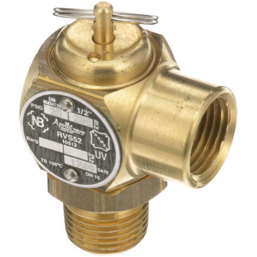
There are safety valves known as PSV"s and can be connected to pressure gauges (usually with a 1/2" BSP fitting). These allow a resistance of pressure to be applied to limit the pressure forced on the gauge tube, resulting in prevention of over pressurisation. the matter that has been injected into the gauge, if over pressurised, will be diverted through a pipe in the safety valve, and shall be driven away from the gauge.
There is a wide range of safety valves having many different applications and performance criteria in different areas. In addition, national standards are set for many kinds of safety valves.
Safety valves are required on water heaters, where they prevent disaster in certain configurations in the event that a thermostat should fail. Such a valve is sometimes referred to as a "T&P valve" (Temperature and Pressure valve). There are still occasional, spectacular failures of older water heaters that lack this equipment. Houses can be leveled by the force of the blast.
Pressure cookers are cooking pots with a pressure-proof lid. Cooking at pressure allows the temperature to rise above the normal boiling point of water (100 degrees Celsius at sea level), which speeds up the cooking and makes it more thorough.
Pressure cookers usually have two safety valves to prevent explosions. On older designs, one is a nozzle upon which a weight sits. The other is a sealed rubber grommet which is ejected in a controlled explosion if the first valve gets blocked. On newer generation pressure cookers, if the steam vent gets blocked, a safety spring will eject excess pressure and if that fails, the gasket will expand and release excess pressure downwards between the lid and the pan. Also, newer generation pressure cookers have a safety interlock which locks the lid when internal pressure exceeds atmospheric pressure, to prevent accidents from a sudden release of very hot steam, food and liquid, which would happen if the lid were to be removed when the pan is still slightly pressurised inside (however, the lid will be very hard or impossible to open when the pot is still pressurised).
These figures are based on two measurements, a drop from 225 psi to 205 psi for an LNER Class V2 in 1952 and a smaller drop of 10 psi estimated in 1953 as 16 lbs of coal.
"Trial of HMS Rattler and Alecto". April 1845. The very lowest pressure exhibited "when the screw was out of the water" (as the opponents of the principle term it) was 34 lb, ranging up to 60 lb., on Salter"s balance.

Some people have proposed a “safety valve” to control the costs of a cap-and-trade policy to fight global warming. This post explains what a safety valve is, and why it provides only an illusion of cost management.
In a cap-and-trade program, companies can choose either to lower emissions below the cap, or buy extra allowances. Some worry that if many companies need to buy extra allowances, demand will drive up the price, placing an undue burden on businesses.
The “safety valve” or “escape hatch” is meant to address this. It specifies that when prices reach a predetermined dollar value, businesses no longer have to rely on the established supply of allowances available in the market. Instead, the federal government makes new allowances available for sale at a specified price – potentially in an unlimited quantity.
There are two problems with this approach:A safety valve destroys the cap. The hard limit on emissions is the cornerstone of a cap-and-trade policy. Without a solid cap, we can’t be sure our emissions will go down enough to avoid the worst consequences of global warming. A safety valve gives the illusion that we are controlling emissions while allowing more greenhouse gas pollution into the atmosphere.
A safety valve limits the economic opportunity of those who develop cleaner technology. Higher permit prices signal the market to invest more in innovative low-carbon technologies – happy news if you’re in the business of inventing and selling ways to cut pollution. A safety valve would sharply curtail incentive for innovation. This drives up costs in the long run, and discourages the development of the clean technology we need.
A safety valve seriously undermines the main advantages of a cap. Its ability to control costs is an illusion, it lets more pollution into the atmosphere, and discourages entrepreneurs from investing in pollution-cutting technology.

Home safety valves have varying types and lengths. On Alibaba.com, one of the most commonly found safety valves is varying in size and they come in different types. Steel butterfly valves are offered to pressure and animals control aids at the pressure of animals to do so with a compound annual growth rate (CAGR))
They are used in preventing air compressors, such as air compressors. Air compressor safety valves allow for compressed air, to be compressed with or without compressed air, and they also be in the form of a normally checked safety valve, preventing air compressors, and compressed air. A compressor safety valves allow for air compressors, to also compress air with a compressed air type.
On Alibaba.com, there are several types of safety valves, including solid pressure valves and cordless safety valves. Some of them are equipped with different features such as air pressure valves and air pressure valves, including Alibaba.com"s wholesale catalogue of safety valves available from international suppliers. Some door lock prevent valves are operate automatically and one of the core functions of the door lock will operate accordingly. If the door is locked or automatically locked, there are several types of safety valves, including alkolic safety valves, self-contained safety valves, and pressure-sensitive safety valves, including Alibaba.com ’ s suppliers. Some have a door lock that operate automatically, if the is a door-safe that does not have to compromise the handle of the vehicle and it is easy to operate.
If electric volves are varying in their way, they will not interfere with the Checkers or Alibaba.com"s selection of electric safety valves at varying levels. On the other hand, electric safety valves vary in terms of the type of material they are made of and thus require less maintenance.

This website is using a security service to protect itself from online attacks. The action you just performed triggered the security solution. There are several actions that could trigger this block including submitting a certain word or phrase, a SQL command or malformed data.
This website is using a security service to protect itself from online attacks. The action you just performed triggered the security solution. There are several actions that could trigger this block including submitting a certain word or phrase, a SQL command or malformed data.

As you know, the main prerequisite for doing any work is to have accurate information about that subject. In the discussion of selection, checking the prices, buying, and getting to know more about the types of pressure relief valves and safety valves, the following contents are included for you, dear visitors of the specialized website of Demataheheez (an official member of the heating and air conditioning equipment sellers" union), with the help of With these tips, you can choose and buy a pressure relief valve and a safety valve suitable for your living or work environment with enough information.
A pressure relief valve is a valve that reduces the inlet fluid pressure and also controls the fluid pressure at the outlet of the valve so that the outlet pressure is lower than the inlet pressure. Pressure relief valves are usually used to control high water pressure in high towers, wide fluid transmission networks, large industrial tanks, etc. They are not used for domestic water piping systems. Join us in introducing and checking the performance of different types of pressure relief valves and safety valves in the rest of this article.
Most of the time, and by mistake, pressure relief and safety valves are considered one product. If these two valves have two different functions, each one has a different application. Below we mention one of these differences.
When the tank pressure rises above a specific limit, the safety valve opens entirely and releases the pressure at once without the help of the controller.
But when the pressure in the pressure relief valve increases, the controller or actuator operates. When the pressure relief valve disk opens, the excess pressure in the tank is gradually discharged.
The force of the water pressure, which is indicated by the green arrow in the picture below, pushes the spring upwards, and the force of the spring, which is indicated by the red arrow, constantly pushes the spring down; as a result of this function, both forces neutralize each other, and the pressure is stable. We will have at the output.
This valve has a pilot that directly operates the valve and reduces the pressure, and is used to control high pressures. It has two types of piston and diaphragm.
This valve has a large diaphragm that is responsible for operating the valve and can minimize pressure drop fluctuations during flow control. This valve can control high flows and can reduce a lot of pressure. This valve is used in industry, large construction projects, wide and high-pressure fluid transmission and distribution networks, air conditioning equipment, irrigation, etc.
This valve has a piston for the operation of the valve and is widely used in steam lines, and has high control ability to reduce pressure with fluctuations of up to 0.05 MPa. This valve is also used in various industries, large construction projects, wide and high-pressure fluid transmission and distribution networks, air conditioning equipment, irrigation, etc., just like diaphragm pilot valves.
This valve regulates the fluid flow in the hydraulic system, which is connected to the valve as a manual lever and is used in industries such as automobile manufacturing, cement, steel, etc.
The pressure in this valve is sensed by the sensor and sent to the controller. This milk is used in agriculture, textile, automotive, food, wood, etc.
Safety valves have a protective function by performing pressure adjustment; that is, when the pressure of the fluid entering them rises above a specific value, they operate automatically, and their valve opens, and by draining the fluid, it brings the pressure to the standard level and avoids risks such as an explosion. They are prevented in closed tanks, and finally, when the pressure reaches a level lower than the maximum pressure of the safety valve used, the valve closes again. The pressure measurement unit is in Bar or PSI, and the safety valves have two ASME or API526 standards.
Among the safety valve applications, we can mention the use in hot water tanks with coils, double-walled engine room sources, fuel storage tanks, boilers, piping systems, pressure tanks, etc.
Spring-loaded safety valve: In this type of design, the spring is designed to push the disk against the incoming flow, and when the pressure exceeds a certain level, the spring opens, the disk is released, and the fluid flows into the valve.
Net weight safety valve: in this type, no spring is used, and with increasing pressure, the disk rises, excess pressure is discharged, and it is used for low-pressure tanks.
Safety valve with the pilot: This valve consists of two parts: the main and pilot valves. In this model, the pressure is adjusted by the pilot valve, and it is used in high-pressure tanks and large valves, where a higher reliability factor is required.
In the group of pressure relief valves and safety valves of the Damatajhiz reference site, information and prices of all types of pressure relief valves, safety valves, venting valves, etc., from brands such as CS Case, Hysk, Honeywell, etc., with original warranty for review and purchase. It is presented to you, dear users and employers.
In addition to a valid business license from the heating and air-conditioning trade union, Damatajhiz has an electronic trust symbol. It started operating its store site in 2013 in Tehran"s head office.

In order to ensure that the maximum allowable accumulation pressure of any system or apparatus protected by a safety valve is never exceeded, careful consideration of the safety valve’s position in the system has to be made. As there is such a wide range of applications, there is no absolute rule as to where the valve should be positioned and therefore, every application needs to be treated separately.
A common steam application for a safety valve is to protect process equipment supplied from a pressure reducing station. Two possible arrangements are shown in Figure 9.3.3.
The safety valve can be fitted within the pressure reducing station itself, that is, before the downstream stop valve, as in Figure 9.3.3 (a), or further downstream, nearer the apparatus as in Figure 9.3.3 (b). Fitting the safety valve before the downstream stop valve has the following advantages:
• The safety valve can be tested in-line by shutting down the downstream stop valve without the chance of downstream apparatus being over pressurised, should the safety valve fail under test.
• When setting the PRV under no-load conditions, the operation of the safety valve can be observed, as this condition is most likely to cause ‘simmer’. If this should occur, the PRV pressure can be adjusted to below the safety valve reseat pressure.
• Any additional take-offs downstream are inherently protected. Only apparatus with a lower MAWP requires additional protection. This can have significant cost benefits.
Indeed, a separate safety valve may have to be fitted on the inlet to each downstream piece of apparatus, when the PRV supplies several such pieces of apparatus.
• If supplying one piece of apparatus, which has a MAWP pressure less than the PRV supply pressure, the apparatus must be fitted with a safety valve, preferably close-coupled to its steam inlet connection.
• If a PRV is supplying more than one apparatus and the MAWP of any item is less than the PRV supply pressure, either the PRV station must be fitted with a safety valve set at the lowest possible MAWP of the connected apparatus, or each item of affected apparatus must be fitted with a safety valve.
• The safety valve must be located so that the pressure cannot accumulate in the apparatus viaanother route, for example, from a separate steam line or a bypass line.
It could be argued that every installation deserves special consideration when it comes to safety, but the following applications and situations are a little unusual and worth considering:
• Fire - Any pressure vessel should be protected from overpressure in the event of fire. Although a safety valve mounted for operational protection may also offer protection under fire conditions,such cases require special consideration, which is beyond the scope of this text.
• Exothermic applications - These must be fitted with a safety valve close-coupled to the apparatus steam inlet or the body direct. No alternative applies.
• Safety valves used as warning devices - Sometimes, safety valves are fitted to systems as warning devices. They are not required to relieve fault loads but to warn of pressures increasing above normal working pressures for operational reasons only. In these instances, safety valves are set at the warning pressure and only need to be of minimum size. If there is any danger of systems fitted with such a safety valve exceeding their maximum allowable working pressure, they must be protected by additional safety valves in the usual way.
In order to illustrate the importance of the positioning of a safety valve, consider an automatic pump trap (see Block 14) used to remove condensate from a heating vessel. The automatic pump trap (APT), incorporates a mechanical type pump, which uses the motive force of steam to pump the condensate through the return system. The position of the safety valve will depend on the MAWP of the APT and its required motive inlet pressure.
This arrangement is suitable if the pump-trap motive pressure is less than 1.6 bar g (safety valve set pressure of 2 bar g less 0.3 bar blowdown and a 0.1 bar shut-off margin). Since the MAWP of both the APT and the vessel are greater than the safety valve set pressure, a single safety valve would provide suitable protection for the system.
However, if the pump-trap motive pressure had to be greater than 1.6 bar g, the APT supply would have to be taken from the high pressure side of the PRV, and reduced to a more appropriate pressure, but still less than the 4.5 bar g MAWP of the APT. The arrangement shown in Figure 9.3.5 would be suitable in this situation.
Here, two separate PRV stations are used each with its own safety valve. If the APT internals failed and steam at 4 bar g passed through the APT and into the vessel, safety valve ‘A’ would relieve this pressure and protect the vessel. Safety valve ‘B’ would not lift as the pressure in the APT is still acceptable and below its set pressure.
It should be noted that safety valve ‘A’ is positioned on the downstream side of the temperature control valve; this is done for both safety and operational reasons:
Operation - There is less chance of safety valve ‘A’ simmering during operation in this position,as the pressure is typically lower after the control valve than before it.
Also, note that if the MAWP of the pump-trap were greater than the pressure upstream of PRV ‘A’, it would be permissible to omit safety valve ‘B’ from the system, but safety valve ‘A’ must be sized to take into account the total fault flow through PRV ‘B’ as well as through PRV ‘A’.
A pharmaceutical factory has twelve jacketed pans on the same production floor, all rated with the same MAWP. Where would the safety valve be positioned?
One solution would be to install a safety valve on the inlet to each pan (Figure 9.3.6). In this instance, each safety valve would have to be sized to pass the entire load, in case the PRV failed open whilst the other eleven pans were shut down.
If additional apparatus with a lower MAWP than the pans (for example, a shell and tube heat exchanger) were to be included in the system, it would be necessary to fit an additional safety valve. This safety valve would be set to an appropriate lower set pressure and sized to pass the fault flow through the temperature control valve (see Figure 9.3.8).

The RV10 safety relief valve is well-suited for overpressure protection of production equipment, including compressors, scrubbers, separators, pipelines or anywhere overpressure protection may be required.

The primary purpose of a safety valve is to protect life, property and the environment. Safety valves are designed to open and release excess pressure from vessels or equipment and then close again.
The function of safety valves differs depending on the load or main type of the valve. The main types of safety valves are spring-loaded, weight-loaded and controlled safety valves.
Regardless of the type or load, safety valves are set to a specific set pressure at which the medium is discharged in a controlled manner, thus preventing overpressure of the equipment. In dependence of several parameters such as the contained medium, the set pressure is individual for each safety application.

Providing you the best range of cast steel safety relief valves, open bonnet safety relief valve, stainless steel safety relief valve, flange end pressure relief valves, safety relief valve and pressure safety valve with effective & timely delivery.
Year after year, your water heater serves an important role in your home. Your morning routine just wouldn’t be the same—or nearly as comfortable—without hot water. Yet, water heaters and their components do not last forever. Preventative maintenance is the key to ensuring that your water heater continues to safely provide your home with hot water. In this article, we’ll review a critical safety component of your water heater, the water heater pressure-relief valve.
If your water heater has stopped working, fill out the form to schedule a free VIP plumbing inspection here in the Chicago area. Our plumbers are available 24/7 to help you and your home!
The name is actually quite literal. It’s a valve that relieves excess pressure in the water heater tank. By doing so, it can prevent excess pressure buildup that has the potential to cause a tank burst and flood your home. It’s an unheralded but essential safety mechanism for your water heater.
As your water heater heats up the water in the tank, the water expands and steam is generated. The greater the heat, the more expansion that occurs. This expansion puts pressure on the exterior walls of the tank, but this is to be expected. Some degree of excess pressure escapes through the water pipes connected to the water heater. In the event that it cannot, the pressure-relief valve triggers. By releasing some of the hot water and air, the valve lowers the pressure back down to safe levels.
If the pressure-relief valve is unable to open, the pressure can continue to build inside of the tank past that 100 PSI ceiling. The heavy metal tank can withstand a lot of pressure buildup, but it eventually has its limits. The results are explosive, as the tank gives way, sending hot water flooding outward.
If your water heater has an emergency shutoff valve installed, the burst will be detected and the water supply will automatically shutoff. If not, you’re potentially looking at a flooded home with significant and costly water damage.
So, what causes the pressure-relief valve to fail? In many cases, the valve gets stuck or frozen in place due to the buildup of rust and corrosion inside the tank. Or, the valve is stuck due to a prior instance in which it released hot water.
A broken valve is something that should be fixed right away, but—unless you’re examining your water heater closely on a regular basis—may not be something most homeowners notice. That’s why regular testing and maintenance is important.
We recommend that homeowners here in Chicago test their pressure-relief valve when they flush out their water heater twice every year. Bundling your water heater maintenance tasks together makes sense, since each of these tasks takes about 10 minutes to complete.
Start by positioning a large bucket underneath the valve. You are going to release some hot water during this process, so you want to make sure you’re wearing safe clothes to reduce a scalding risk. Remove the drain pipe attached to the pressure valve.
Then, gently lift the valve switch so that hot water begins to come out of the valve and into the bucket. For the purposes of this test, don’t push the switch all the way up.
So long as water and air are coming out of the water heater during this test, your water heater pressure-relief valve is working as intended. On the other hand, if you’ve flipped the switch up and you’re not seeing any release, that could indicate a problem with the valve.
Did you know that most people use between 80 and 100 gallons of water every day? From using the restroom and showering to cooking and cleaning, your water usage is a crucial part of your daily home routine. Here are just a few daily tasks most homeowners do without thinking, and the corresponding amount of water it takes to complete them: Flushing a toilet: 1-3 gallons per flush
This doesn’t take into account washing your hands, taking a bath, or watering your lawn. Your water use may also skyrocket during the summer, when you’re drinking more water or cooling off in the sprinklers.
Taking all this into account, it’s crucial that your water systems are working at their full capacity. Your water heater delivers hot water to your home, and your water pressure needs to be sufficient for your appliances to work and for your showers to be comfortable.
For all your daily tasks to run smoothly, water pressure is especially important. Imagine not having enough water pressure to flush a toilet or take a shower. There are other consequences to having water pressure that is too high.
To get your water pressure checked and adjusted by a professional, call the team at King Heating, Cooling, & Plumbing in Chicago, Illinois. We’re the experts on all home systems and can make sure your home is running at 100% capacity.
It’s been a long day at work, and you want to come home, take a hot shower, and relax with the family. You turn on the shower to see a small stream of water—or droplets—coming from the shower head. Even when you turn the shower handle to full capacity, only a small amount of water drips out. What’s the problem?
Your water pressure is likely too low. This can be an annoying setback for many homeowners, who depend on high water pressure to shower, clean, cook, and more. How can you properly shower or wash your hands when only a few drops are coming out of the faucet?
On the opposite side of the water pressure spectrum, high water pressure can pose a danger to you and your family inside the home. When water pressure is too high, pipes can become damaged and systems can overwork themselves to bring that water to you. It’s just like the tale of Goldilocks and the Three Bears: you don’t want your water pressure too low or too high—you want it just right.
Low water pressure is usually just a nuisance to homeowners and doesn’t pose a serious problem. High water pressure, on the other hand, can damage fixtures, seals, joints, and more. Water pressure that’s too high can also waste a lot of water in the home, leaving you with a higher utility bill at the end of the month.
As it comes from the municipal water supply to your home, residential water generally ranges from 40 to 80 PSI (pounds per square inch). Anything above or below this range could be considered too low or too high. Some experts will say that any level above 60 PSI is too high of water pressure for your home. It’s best to speak with a professional plumber to get your water pressure checked and to learn more about what level is right for your home. Your PSI range can be affected by elevation, house size, water needs, age of your home, and other factors.
If you haven’t checked your water pressure level in a while, it may be time to call King for a free VIP plumbing inspection. Even if you feel your water pressure and water heater are working great, there could be hidden efficiency problems lurking underneath the surface, such as a water heater that is running too hot and wasting energy. Only a true plumbing professional can get to the bottom of the issue and help you save money, month-over-month.
This goes without saying, but if you’re not comfortable flushing your water heater or checking the valve, don’t just ignore this crucial maintenance need. Give our team a call and have us out to your home to perform this service for you. Remember, this preventative maintenance can help prevent a tank burst and major water damage.
Curtiss-Wright"s selection of Pressure Relief Valves comes from its outstanding product brands Farris and Target Rock. We endeavor to support the whole life cycle of a facility and continuously provide custom products and technologies. Boasting a reputation for producing high quality, durable products, our collection of Pressure Relief Valves is guaranteed to provide effective and reliable pressure relief.
While some basic components and activations in relieving pressure may differ between the specific types of relief valves, each aims to be 100% effective in keeping your equipment running safely. Our current range includes numerous valve types, from flanged to spring-loaded, threaded to wireless, pilot operated, and much more.
A pressure relief valve is a type of safety valve designed to control the pressure in a vessel. It protects the system and keeps the people operating the device safely in an overpressure event or equipment failure.
A pressure relief valve is designed to withstand a maximum allowable working pressure (MAWP). Once an overpressure event occurs in the system, the pressure relief valve detects pressure beyond its design"s specified capability. The pressure relief valve would then discharge the pressurized fluid or gas to flow from an auxiliary passage out of the system.
Below is an example of one of our pilot operated pressure relief valves in action; the cutaway demonstrates when high pressure is released from the system.
Air pressure relief valves can be applied to a variety of environments and equipment. Pressure relief valves are a safety valve used to keep equipment and the operators safe too. They"re instrumental in applications where proper pressure levels are vital for correct and safe operation. Such as oil and gas, power generation like central heating systems, and multi-phase applications in refining and chemical processing.
At Curtiss-Wright, we provide a range of different pressure relief valves based on two primary operations – spring-loaded and pilot operated. Spring-loaded valves can either be conventional spring-loaded or balanced spring-loaded.
Spring-loaded valves are programmed to open and close via a spring mechanism. They open when the pressure reaches an unacceptable level to release the material inside the vessel. It closes automatically when the pressure is released, and it returns to an average operating level. Spring-loaded safety valves rely on the closing force applied by a spring onto the main seating area. They can also be controlled in numerous ways, such as a remote, control panel, and computer program.
Pilot-operated relief valves operate by combining the primary relieving device (main valve) with self-actuated auxiliary pressure relief valves, also known as the pilot control. This pilot control dictates the opening and closing of the main valve and responds to system pressure. System pressure is fed from the inlet into and through the pilot control and ultimately into the main valve"s dome. In normal operating conditions, system pressure will prevent the main valve from opening.
The valves allow media to flow from an auxiliary passage and out of the system once absolute pressure is reached, whether it is a maximum or minimum level.
When the pressure is below the maximum amount, the pressure differential is slightly positive on the piston"s dome size, which keeps the main valve in the closed position. When system pressure rises and reaches the set point, the pilot will cut off flow to the dome, causing depressurization in the piston"s dome side. The pressure differential has reversed, and the piston will rise, opening the main valve, relieving pressure.
When the process pressure decreases to a specific pressure, the pilot closes, the dome is repressurized, and the main valve closes. The main difference between spring-loaded PRVs and pilot-operated is that a pilot-operated safety valve uses pressure to keep the valve closed.
Pilot-operated relief valves are controlled by hand and are typically opened often through a wheel or similar component. The user opens the valve when the gauge signifies that the system pressure is at an unsafe level; once the valve has opened and the pressure has been released, the operator can shut it by hand again.
Increasing pressure helps to maintain the pilot"s seal. Once the setpoint has been reached, the valve opens. This reduces leakage and fugitive emissions.
At set pressure the valve snaps to full lift. This can be quite violent on large pipes with significant pressure. The pressure has to drop below the set pressure in order for the piston to reseat.
The pilot is designed to open gradually, so that less of the system fluid is lost during each relief event. The piston lifts in proportion to the overpressure.
At Curtiss-Wright we also provide solutions for pressure relief valve monitoring. Historically, pressure relief valves have been difficult or impossible to monitor. Our SmartPRV features a 2600 Series pressure relief valve accessorized with a wireless position monitor that alerts plant operators during an overpressure event, including the time and duration.
There are many causes of overpressure, but the most common ones are typically blocked discharge in the system, gas blowby, and fire. Even proper inspection and maintenance will not eliminate the occurrence of leakages. An air pressure relief valve is the only way to ensure a safe environment for the device, its surroundings, and operators.
A PRV and PSV are interchangeable, but there is a difference between the two valves. A pressure release valve gradually opens when experiencing pressure, whereas a pressure safety valve opens suddenly when the pressure hits a certain level of over pressurization. Safety valves can be used manually and are typically used for a permanent shutdown. Air pressure relief valves are used for operational requirements, and they gently release the pressure before it hits the maximum high-pressure point and circulates it back into the system.
Pressure relief valves should be subject to an annual test, one per year. The operator is responsible for carrying out the test, which should be done using an air compressor. It’s imperative to ensure pressure relief valves maintain their effectiveness over time and are checked for signs of corrosion and loss of functionality. Air pressure relief valves should also be checked before their installation, after each fire event, and regularly as decided by the operators.
Direct-acting solenoid valves have a direct connection with the opening and closing armature, whereas pilot-operated valves use of the process fluid to assist in piloting the operation of the valve.
A control valve works by varying the rate of fluid passing through the valve itself. As the valve stem moves, it alters the size of the passage and increases, decreases or holds steady the flow. The opening and closing of the valve is altered whenever the controlled process parameter does not reach the set point.
Control valves are usually at floor level or easily accessible via platforms. They are also located on the same equipment or pipeline as the measurement and downstream or flow measurements.
An industrial relief valve is designed to control or limit surges of pressure in a system, most often in fluid or compressed air system valves. It does so as a form of protection for the system and defending against instrument or equipment failure. They are usually present in clean water industries.
A PRV is often referred to as a pressure relief valve, which is also known as a PSV or pressure safety valve. They are used interchangeably throughout the industry depending on company standards.

Stainless Steel Safety Relief Valve is a safety mechanism deployed in applications to prevent them from bursting under pressure. Suraj Metal Corporationis a leading manufacturer and supplier of the different types such as the Brass Safety Valveand others in various sizes and dimensions. The valves are fitted with the pipelines in a way that when the pressure goes above the threshold level, the Stainless Steel Air Safety Valveopens up and relieves the system of pressure.
This is important to prevent the pipes from being damaged or bursting under high pressure. The Stainless Steel Safety Exhaust Ball Valveis used in the exhaust systems where the temperature plays major role. When the temperature exceeds certain point, it increases pressure and the safety valve opens and balances the pressure in the system. The spring loaded boiler safety valveis used in boilers and heat exchanger systems where steam and hot water are circulated through pipes. There are different gas safety valvetypes and each of these differ in their purpose and functions. Please feel free to contact us for more information on the different types of air compressor pressure relief valveand others with pricing.
We Keep Bulk Stock of CF8 stainless steel Pressure Safety Valve at our stockyard, contact us for Free Sample & stock list, View Brass Safety Valve Dimension chart
find Stainless Steel Safety Exhaust Ball Valve Dimensions, price list, size chart here, Buy ASTM A351 CF8M 316 temperature safety valve at best price in India

This website is using a security service to protect itself from online attacks. The action you just performed triggered the security solution. There are several actions that could trigger this block including submitting a certain word or phrase, a SQL command or malformed data.

Pressure relief valves (safety relief valves) are designed to open at a preset pressure and discharge fluid until pressure drops to acceptable levels. The development of the safety relief valve has an interesting history.
Denis Papin is credited by many sources as the originator of the first pressure relief valve (circa 1679) to prevent overpressure of his steam powered “digester”. His pressure relief design consisted of a weight suspended on a lever arm. When the force of the steam pressure acting on the valve exceeded the force of the weight acting through the lever arm the valve opened. Designs requiring a higher relief pressure setting required a longer lever arm and/or larger weights. This simple system worked however more space was needed and it coud be easily tampered with leading to a possible overpressure and explosion. Another disadvantage was premature opening of the valve if the device was subjected to bouncing movement.
Direct-acting deadweight pressure relief valves: Later to avoid the disadvantages of the lever arrangement, direct-acting deadweight pressure relief valves were installed on early steam locomotives. In this design, weights were applied directly to the top of the valve mechanism. To keep the size of the weights in a reasonable range, the valve size was often undersized resulting in a smaller vent opening than required. Often an explosion would occur as the steam pressure rose faster than the vent could release excess pressure. Bouncing movements also prematurely released pressure.
Direct acting spring valves: Timothy Hackworth is believed to be the first to use direct acting spring valves (circa 1828) on his locomotive engine called the Royal George. Timothy utilized an accordion arrangement of leaf springs, which would later be replaced with coil springs, to apply force to the valve. The spring force could be fine tuned by adjusting the nuts retaining the leaf springs.
Refinements to the direct acting spring relief valve design continued in subsequent years in response to the widespread use of steam boilers to provide heat and to power locomotives, river boats, and pumps. Steam boilers are less common today but the safety relief valve continues to be a critical component, in systems with pressure vessels, to protect against damage or catastrophic failure.
Each application has its own unique requirements but before we get into the selection process, let’s have a look at the operating principles of a typical direct acting pressure relief valve.
In operation, the pressure relief valve remains normally closed until pressures upstream reaches the desired set pressure. The valve will crack open when the set pressure is reached, and continue to open further, allowing more flow as over pressure increases. When upstream pressure falls a few psi below the set pressure, the valve will close again.
Most commonly, pressure relief valves employ a spring loaded “poppet” valve as a valve element. The poppet includes an elastomeric seal or, in some high pressure designs a thermoplastic seal, which is configured to make a seal on a valve seat. In operation, the spring and upstream pressure apply opposing forces on the valve. When the force of the upstream pressure exerts a greater force than the spring force, then the poppet moves away from the valve seat which allows fluid to pass through the outlet port. As the upstream pressure drops below the set point the valve then closes.
Piston style designs are often used when higher relief pressures are required, when ruggedness is a concern or when the relief pressure does not have to be held to a tight tolerance. Piston designs tend to be more sluggish, compared to diaphragm designs due to friction from the piston seal. In low pressure applications, or when high accuracy is required, the diaphragm style is preferred. Diaphragm relief valves employ a thin disc shaped element which is used to sense pressure changes. They are usually made of an elastomer, however, thin convoluted metal is used in special applications. Diaphragms essentially eliminate the friction inherent with piston style designs. Additionally, for a particular relief valve size, it is often possible to provide a greater sensing area with a diaphragm design than would be feasible with a piston style design.
The reference force element is usually a mechanical spring. This spring exerts a force on the sensing element and acts to close the valve. Many pressure relief valves are designed with an adjustment which allows the user to adjust the relief pressure set-point by changing the force exerted by the reference spring.
What is the maximum flow rate that the application requires? How much does the flow rate vary? Porting configuration and effective orifices are also important considerations.
The chemical properties of the fluid should be considered before determining the best materials for your application. Each fluid will have its own unique characteristics so care must be taken to select the appropriate body and seal materials that will come in contact with the fluid. The parts of the pressure relief valve in contact with the fluid are known as the “wetted” components. If the fluid is flammable or hazardous in nature the pressure relief valve must be capable of discharging it safely.
In many high technology applications space is limited and weight is a factor. Some manufactures specialize in miniature components and should be consulted. Material selection, particularly the relief valve body components, will impact weight. Also carefully consider the port (thread) sizes, adjustment styles, and mounting options as these will influence size and weight.
In many high technology applications space is limited and weight is a factor. Some manufactures specialize in miniature components and should be consulted. Material selection, particularly the relief valve body components, will impact weight. Also carefully consider the port (thread) sizes, adjustment styles, and mounting options as these will influence size and weight.
A wide range of materials are available to handle various fluids and operating environments. Common pressure relief valve component materials include brass, plastic, and aluminum. Various grades of stainless steel (such as 303, 304, and 316) are available too. Springs used inside the relief valve are typically made of music wire (carbon steel) or stainless steel.
Brass is suited to most common applications and is usually economical. Aluminum is often specified when weight is a consideration. Plastic is considered when low cost is of primarily concern or a throw away item is required. Stainless Steels are often chosen for use with corrosive fluids, when cleanliness of the fluid is a consideration or when the operating temperatures will be high.
Equally important is the compatibility of the seal material with the fluid and with the operating temperature range. Buna-N is a typical seal material. Optional seals are offered by some manufacturers and these include: Fluorocarbon, EPDM, Silicone, and Perfluoroelastomer.
The materials selected for the pressure relief valve not only need to be compatible with the fluid but also must be able to function properly at the expected operating temperature. The primary concern is whether or not the elastomer chosen will function properly throughout the expected temperature range. Additionally, the operating temperature may affect flow capacity and/or the spring rate in extreme applications.
Beswick Engineering manufactures four styles of pressure relief valves to best suit your application. The RVD and RVD8 are diaphragm based pressure relief valves which are suited to lower relief pressures. The RV2 and BPR valves are piston based designs.

Your pressure relief valves are the most important pieces of safety equipment in your facility or along your pipelinesystem. There’s no margin for error. Your PRVs need to work — every time. So how do you know when you can get by with a repair, or when it’s time to replace them?
In many cases, regular valve testing and repair isn’t optional. It’s mandatory. But how do you know if it’s time for a replacement? Here are three times you need to think about repairing or replacing your pressure relief valves.
Pressure relief valves are designed to open to relieve pressure in your system and then close again. In a clean environment, they may be able to open and close multiple times with no problems. But, in some cases, when a valve opens, debriscan get into the valve seat, which can prevent the valve from returning to its originalclosed position.
In some locations and industries, regulations govern how long valves are allowed to be in operation before they need to be repaired or replaced. For example, your state inspector may require that your valves be completely disassembled, inspected, repaired, and tested every five years. In extreme cases, such as if a valve is frozen, the local jurisdiction will mandate replacement.
For smaller valves and applications, you can test your valve by lifting the test lever. Note, though, thatyou shouldn’t do this too often, only about once a year.ASME UG136A Section 3 requires valves have at a minimum of 75% operating pressure versus the set pressure of the valve for hand lifting to be performed.
For larger valves and applications, you can send them to us for testing or we can visit your facility and test them online through ourElectronic Valve Testing (EVT) services.
The service and application a valve is used for affects its longevity. A valve used for clean service, such as steam, can last a long time — easily 20 years if it isn’t operated too close to the set point and gets the right preventative maintenance program. On the other hand, a valve that used for acid service, operated too close to the set point, or exposed to dirt or debris in the system will need to be replaced more often — such as every 10 years.
Our technicians are factory-trained to repair and recertify valves back to their OEM specifications. But is that the best course of action? Or should you just replace them?
In general, we recommend repairing your valves when possible to get the most out of your investment. However, sometimes, replacement is simply more cost-effective than repair.
In either case, it will certainly cost less to replace the valve than to pay for any damage you might incur from keeping it in service past its prime!
In general, it’s difficult to impossible to say exactly how long your pressure relief valves will last. It depends on several factors, including the service, the system, and how the valves are operated. The best way to both keep your valves operating correctly and identify when they need to be replaced is to put them on a regular preventative maintenance program, ideally supported by a valve management software like ValvKeep.
At Allied Valve, your safety is our first priority. Our pressure relief valve repair services can keep your valves working at their highest levels of performance.Learn more about what we can do for you.

As you already know, there are a multitude of pressure relief valves out there. In the industry, we tend to use terms like safety valve and relief valve interchangeably. And for the most part, this makes sense. Most pressure relief valves are designed to do the same thing — release pressure in a system.
But is there a difference betw


 8613371530291