
safety valve for compressed air free sample
An OSHA COMPRESSED AIR SAFETY SHUT-OFF VALVES should be placed immediately after the air control shut off valve and before the hose on a compressor, and after each discharge port that a hose is connected to.
Before starting the compressor the air control valve should be closed completely. When the compressor unloads, open the air shut off control valve very slowly. Full port ball valves tend to work better than gate or butterfly type valves.
The air shut off control valve must be fully open for the OSHA COMPRESSED AIR SAFETY SHUT-OFF VALVES to work. Some portable air compressor manufacturers recommend start-up with the air control valve slightly open. In this case you may have to close the valve and reopen it slowly to the full open position, or wait for the safety shut-off valve to reset itself.
If the OSHA COMPRESSED AIR SAFETY SHUT-OFF VALVES fails to operate despite meeting all condi-tions, check the hose line for obstructions or a hose mender restricting normal air flow.
• Turn on air supply slowly (to avoid tripping OSHA safety valve). Prior to fully reaching operation conditions, the OSHA COMPRESSED AIR SAFETY SHUT-OFF VALVES should suddenly activate and stop air flow.
• If the OSHA COMPRESSED AIR SAFETY SHUT-OFF VALVE is not activated the unit should be disconnected and the lower flow range OSHA COMPRESSED AIR SAFETY SHUT-OFF VALVES should be used. This means you need to use a different valve with a lower scfm range.
• At temperatures below 40°F ensure that OSHA COMPRESSED AIR SAFETY SHUT-OFF VALVES are not subject to icy conditions which may prevent proper functioning.

Pressure relief valve is related to Microchek.com. We offer competitive pricing and reliability because we are the manufacture. Parts are molded and assembled in the U.S. The Microchek system incorporates this cartridge and a wide selection of end pieces to accommodate most connection requirements. The Microchek valve is a cartridge check valve incorporating an innovative guided poppet design. Relief valves are used to hold a fluid circuit or reservoir at a positive or negative pressure. We can select valves that fall into a specific cracking pressure range if needed. The Microchek valve has a low pressure drop and can be specified with a wide variety of cracking pressures.
Our staff is available to advise you on your applications. Please ask for a FREE sample that meets your needs. If your design requires a unique configuration, we will be pleased to quote your needs.The system is available in a variety of polymers and elastomers to ensure compatibility with most liquids and gases.
The Microchek valve is a cartridge check valve incorporating an innovative guided poppet design. Relief valves are used to hold a fluid circuit or reservoir at a positive or negative pressure. We want the opportunity to help you solve your flow control applications and we can build special configurations.

In order to ensure that the maximum allowable accumulation pressure of any system or apparatus protected by a safety valve is never exceeded, careful consideration of the safety valve’s position in the system has to be made. As there is such a wide range of applications, there is no absolute rule as to where the valve should be positioned and therefore, every application needs to be treated separately.
A common steam application for a safety valve is to protect process equipment supplied from a pressure reducing station. Two possible arrangements are shown in Figure 9.3.3.
The safety valve can be fitted within the pressure reducing station itself, that is, before the downstream stop valve, as in Figure 9.3.3 (a), or further downstream, nearer the apparatus as in Figure 9.3.3 (b). Fitting the safety valve before the downstream stop valve has the following advantages:
• The safety valve can be tested in-line by shutting down the downstream stop valve without the chance of downstream apparatus being over pressurised, should the safety valve fail under test.
• When setting the PRV under no-load conditions, the operation of the safety valve can be observed, as this condition is most likely to cause ‘simmer’. If this should occur, the PRV pressure can be adjusted to below the safety valve reseat pressure.
Indeed, a separate safety valve may have to be fitted on the inlet to each downstream piece of apparatus, when the PRV supplies several such pieces of apparatus.
• If supplying one piece of apparatus, which has a MAWP pressure less than the PRV supply pressure, the apparatus must be fitted with a safety valve, preferably close-coupled to its steam inlet connection.
• If a PRV is supplying more than one apparatus and the MAWP of any item is less than the PRV supply pressure, either the PRV station must be fitted with a safety valve set at the lowest possible MAWP of the connected apparatus, or each item of affected apparatus must be fitted with a safety valve.
• The safety valve must be located so that the pressure cannot accumulate in the apparatus viaanother route, for example, from a separate steam line or a bypass line.
It could be argued that every installation deserves special consideration when it comes to safety, but the following applications and situations are a little unusual and worth considering:
• Fire - Any pressure vessel should be protected from overpressure in the event of fire. Although a safety valve mounted for operational protection may also offer protection under fire conditions,such cases require special consideration, which is beyond the scope of this text.
• Exothermic applications - These must be fitted with a safety valve close-coupled to the apparatus steam inlet or the body direct. No alternative applies.
• Safety valves used as warning devices - Sometimes, safety valves are fitted to systems as warning devices. They are not required to relieve fault loads but to warn of pressures increasing above normal working pressures for operational reasons only. In these instances, safety valves are set at the warning pressure and only need to be of minimum size. If there is any danger of systems fitted with such a safety valve exceeding their maximum allowable working pressure, they must be protected by additional safety valves in the usual way.
In order to illustrate the importance of the positioning of a safety valve, consider an automatic pump trap (see Block 14) used to remove condensate from a heating vessel. The automatic pump trap (APT), incorporates a mechanical type pump, which uses the motive force of steam to pump the condensate through the return system. The position of the safety valve will depend on the MAWP of the APT and its required motive inlet pressure.
This arrangement is suitable if the pump-trap motive pressure is less than 1.6 bar g (safety valve set pressure of 2 bar g less 0.3 bar blowdown and a 0.1 bar shut-off margin). Since the MAWP of both the APT and the vessel are greater than the safety valve set pressure, a single safety valve would provide suitable protection for the system.
Here, two separate PRV stations are used each with its own safety valve. If the APT internals failed and steam at 4 bar g passed through the APT and into the vessel, safety valve ‘A’ would relieve this pressure and protect the vessel. Safety valve ‘B’ would not lift as the pressure in the APT is still acceptable and below its set pressure.
It should be noted that safety valve ‘A’ is positioned on the downstream side of the temperature control valve; this is done for both safety and operational reasons:
Operation - There is less chance of safety valve ‘A’ simmering during operation in this position,as the pressure is typically lower after the control valve than before it.
Also, note that if the MAWP of the pump-trap were greater than the pressure upstream of PRV ‘A’, it would be permissible to omit safety valve ‘B’ from the system, but safety valve ‘A’ must be sized to take into account the total fault flow through PRV ‘B’ as well as through PRV ‘A’.
A pharmaceutical factory has twelve jacketed pans on the same production floor, all rated with the same MAWP. Where would the safety valve be positioned?
One solution would be to install a safety valve on the inlet to each pan (Figure 9.3.6). In this instance, each safety valve would have to be sized to pass the entire load, in case the PRV failed open whilst the other eleven pans were shut down.
If additional apparatus with a lower MAWP than the pans (for example, a shell and tube heat exchanger) were to be included in the system, it would be necessary to fit an additional safety valve. This safety valve would be set to an appropriate lower set pressure and sized to pass the fault flow through the temperature control valve (see Figure 9.3.8).

A safety valve must always be sized and able to vent any source of steam so that the pressure within the protected apparatus cannot exceed the maximum allowable accumulated pressure (MAAP). This not only means that the valve has to be positioned correctly, but that it is also correctly set. The safety valve must then also be sized correctly, enabling it to pass the required amount of steam at the required pressure under all possible fault conditions.
Once the type of safety valve has been established, along with its set pressure and its position in the system, it is necessary to calculate the required discharge capacity of the valve. Once this is known, the required orifice area and nominal size can be determined using the manufacturer’s specifications.
In order to establish the maximum capacity required, the potential flow through all the relevant branches, upstream of the valve, need to be considered.
In applications where there is more than one possible flow path, the sizing of the safety valve becomes more complicated, as there may be a number of alternative methods of determining its size. Where more than one potential flow path exists, the following alternatives should be considered:
This choice is determined by the risk of two or more devices failing simultaneously. If there is the slightest chance that this may occur, the valve must be sized to allow the combined flows of the failed devices to be discharged. However, where the risk is negligible, cost advantages may dictate that the valve should only be sized on the highest fault flow. The choice of method ultimately lies with the company responsible for insuring the plant.
For example, consider the pressure vessel and automatic pump-trap (APT) system as shown in Figure 9.4.1. The unlikely situation is that both the APT and pressure reducing valve (PRV ‘A’) could fail simultaneously. The discharge capacity of safety valve ‘A’ would either be the fault load of the largest PRV, or alternatively, the combined fault load of both the APT and PRV ‘A’.
This document recommends that where multiple flow paths exist, any relevant safety valve should, at all times, be sized on the possibility that relevant upstream pressure control valves may fail simultaneously.
The supply pressure of this system (Figure 9.4.2) is limited by an upstream safety valve with a set pressure of 11.6 bar g. The fault flow through the PRV can be determined using the steam mass flow equation (Equation 3.21.2):
Once the fault load has been determined, it is usually sufficient to size the safety valve using the manufacturer’s capacity charts. A typical example of a capacity chart is shown in Figure 9.4.3. By knowing the required set pressure and discharge capacity, it is possible to select a suitable nominal size. In this example, the set pressure is 4 bar g and the fault flow is 953 kg/h. A DN32/50 safety valve is required with a capacity of 1 284 kg/h.
Where sizing charts are not available or do not cater for particular fluids or conditions, such as backpressure, high viscosity or two-phase flow, it may be necessary to calculate the minimum required orifice area. Methods for doing this are outlined in the appropriate governing standards, such as:
Coefficients of discharge are specific to any particular safety valve range and will be approved by the manufacturer. If the valve is independently approved, it is given a ‘certified coefficient of discharge’.
This figure is often derated by further multiplying it by a safety factor 0.9, to give a derated coefficient of discharge. Derated coefficient of discharge is termed Kdr= Kd x 0.9
Critical and sub-critical flow - the flow of gas or vapour through an orifice, such as the flow area of a safety valve, increases as the downstream pressure is decreased. This holds true until the critical pressure is reached, and critical flow is achieved. At this point, any further decrease in the downstream pressure will not result in any further increase in flow.
A relationship (called the critical pressure ratio) exists between the critical pressure and the actual relieving pressure, and, for gases flowing through safety valves, is shown by Equation 9.4.2.
For gases, with similar properties to an ideal gas, ‘k’ is the ratio of specific heat of constant pressure (cp) to constant volume (cv), i.e. cp : cv. ‘k’ is always greater than unity, and typically between 1 and 1.4 (see Table 9.4.8).
For steam, although ‘k’ is an isentropic coefficient, it is not actually the ratio of cp : c. As an approximation for saturated steam, ‘k’ can be taken as 1.135, and superheated steam, as 1.3. As a guide, for saturated steam, critical pressure is taken as 58% of accumulated inlet pressure in absolute terms.
Overpressure - Before sizing, the design overpressure of the valve must be established. It is not permitted to calculate the capacity of the valve at a lower overpressure than that at which the coefficient of discharge was established. It is however, permitted to use a higher overpressure (see Table 9.2.1, Module 9.2, for typical overpressure values). For DIN type full lift (Vollhub) valves, the design lift must be achieved at 5% overpressure, but for sizing purposes, an overpressure value of 10% may be used.
For liquid applications, the overpressure is 10% according to AD-Merkblatt A2, DIN 3320, TRD 421 and ASME, but for non-certified ASME valves, it is quite common for a figure of 25% to be used.
Backpressure - The sizing calculations in the AD-Merkblatt A2, DIN 3320 and TRD 421 standards account for backpressure in the outflow function,(Ψ), which includes a backpressure correction.
Two-phase flow - When sizing safety valves for boiling liquids (e.g. hot water) consideration must be given to vaporisation (flashing) during discharge. It is assumed that the medium is in liquid state when the safety valve is closed and that, when the safety valve opens, part of the liquid vaporises due to the drop in pressure through the safety valve. The resulting flow is referred to as two-phase flow.
The required flow area has to be calculated for the liquid and vapour components of the discharged fluid. The sum of these two areas is then used to select the appropriate orifice size from the chosen valve range. (see Example 9.4.3)
Many standards do not actually specify sizing formula for two-phase flow and recommend that the manufacturer be contacted directly for advice in these instances.

You may not worry often, if at all, about whether or not your air compressor is running safely. And you really don’t have to, because compressor manufacturers do. From the pressure rating on the air storage tank to emergency stop buttons, air compressors are designed with safety in mind.
But that doesn’t mean you should never think about your compressor’s safety features. In most cases, they need to be inspected regularly to make sure they’re working properly. One key safety feature that should be inspected regularly is the air pressure relief valve (PRV), sometimes called a safety relief valve.
The pressure relief valve is a safety valve that protects the compressor component that it’s attached to from being exposed to a pressure above its rated maximum operating pressure. This rating, called the maximum working pressure (MWP), is the pressure that the vessel has been certified to continuously operate at safely.
So when a compressor is running at or below its maximum working pressure—in other words, when it’s running “normally”—the relief valve doesn’t do anything.
However, when the air pressure inside a compressor exceeds its MWP, the pressure relief valve will activate to “blow off” the excessive pressure within the compressor. Without a relief valve, the storage tank could rupture from the excessive pressure, damaging the compressor itself, possibly other property near it, and even causing injuries (or worse) to anyone standing nearby.
Before we can talk about how the air pressure relief valve works, we first need to look at how air pressure inside a compressor is managed when everything is running normally.
Under normal circumstances, the air pressure in a compressor is controlled by a pressure switch in an electro/mechanical control system or, in the case of an electronic controller, a pressure transducer and controller settings. When the cut-out set pressure for the pressure switch is reached, the compressor will stop compressing air (unload) until the cut-in set pressure is reached, at which time it will start compressing air again (load). If the pressure switch fails, the compressor would not be able to start compressing air again, or potentially worse, not be able to stop. Most compressors also have a high-pressure safety switch that should stop the compressor if the pressure exceeds the unload set point.
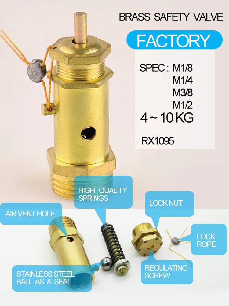
A pressure relief valve is a straightforward safety backup to the pressure switch and high-pressure switch, or the controller set points, should any of these components fail with the compressor running. The safety relief valve is set above the high-pressure safety switch and generally at or below the vessel’s maximum operating pressure. Inside the valve is a spring, and the pressure created by the spring’s tension keeps the valve closed under normal operating conditions. However, as the air pressure increases in pressure vessels (like the storage tank), it eventually exceeds the rated pressure of the relief valve, causing the relief valve to open and the excess pressure to be “blown off” to the atmosphere.
If the pressure relief valve fails open, air will continually vent to the atmosphere, preventing the air stream from becoming fully pressurized. The compressor should be shut down and the relief valve replaced before the compressor is restarted. The open relief valve will likely cause a loss of production and possible danger to personnel as a result of the flow of high-pressure air with flying debris and an unsafe sound level.
A pressure relief valve failing closed presents a potentially more dangerous situation. As noted earlier, the relief valve exists to allow excessive pressure to be “blown off” so that the air pressure inside the compressor’s pressure vessels don’t exceed their rated specifications. If the valve fails closed, this pressure venting can’t happen. Unless compressed air demand matches the compressed air supply, the pressure inside the compressor will continue to build. Eventually, the pressure increase would cause the storage tank to rupture, damaging the compressor and possibly causing additional damage and injury to property and people nearby.
If the relief valve is opening because the air pressure in the compressor has exceeded the valve’s pressure set point, that means the valve is working and doing what it was designed to do. But because this indicates the MWP of the compressor has been exceeded, the condition that’s causing excessive pressure should be diagnosed and corrected.
If the relief valve opening wasn’t caused by excessive pressure inside the compressor, then the valve is most likely “failing open”. Most likely, this is because the valve has become “soft” over time, i.e. the valve spring is providing less counterpressure, so it’s opening at a lower pressure than it should.
Whether the valve opened because of excessive pressure in the compressor or because the valve is failing, you should have your local air compressor distributor inspect your compressor before running it again for two reasons:
First, your distributor can determine whether the valve opened due to a failing relief valve or excessive compressors pressure and perform any needed maintenance or service to get your compressor running efficiently and safely again.
Second, regardless of why the pressure relief valve opened, replacing it may be recommended to ensure safe compressor operation, depending on the valve manufacturer. (Replacement is recommended for Sullair compressors.)
Important: Running the compressor after the relief valve has opened, regardless of the reason why it opened, can put both your property at risk of damage and people at risk of injury (or worse). While this may be obvious if the compressor is building up excess pressure, it also applies if the valve failed open. As noted above, even a valve that fails open poses some risk, and next time it could fail closed.
Given how critical a working air pressure relief valve is to the safe and efficient operation of your air compressor, you may wonder whether you need to do any regular inspecting or testing of the valve to make sure it is working. Because this can vary by manufacturer, you should consult your owner’s manual or contact your local air compressor distributor for frequency and type of inspection needed. For most Sullair compressors, inspection for damage or leakage is recommended, but testing is not recommended, as doing so may compromise the valve’s performance.
However, one thing you should do is schedule regular maintenance with your local air compressor distributor. As part of regular maintenance, a service technician can inspect the PRV and let you know it’s at an age or in a condition at which the manufacturer recommends replacement. Also, problems with the compressor’s performance, e.g. not reaching normal operating pressure, may help the service technician identify a failing relief valve after ruling out other possible causes.
When a pressure vessel like a receiver, sump tank or other storage vessel is purchased separately from the compressor, it may not be supplied with a pressure relief valve. To ensure its safe operation, you should add a PRV.
When selecting a PRV to add to the pressure vessel, you must choose a valve with a pressure set point set at or below the maximum working pressure of the vessel. You will find the MWP (and other useful information) on a tag welded to the pressure vessel. Also, flow capacity of the PRV must meet or exceed the total compressed air supplied to the vessel.
For example, if you have two compressors with capacities of 500 and 750 cfm (14.2 and 21.2 m³/min), and a pressure vessel with a maximum working pressure of 200 psi (13.8 bar), the minimum settings for a pressure relief valve would be 1250 cfm (35.4 m³/min) and a set point 200 psi (13.8 bar) or less.
Finally, when attaching the valve to the vessel, the porting must not be reduced to a size less than the size of the inlet port of the pressure relief valve.
Because the pressure relief valve is critical to the safe operation of your compressed air system, if you’re not sure how to select the correct PRV and properly and safely add it to the pressure vessel, contact your local air compressor distributor. They have the experience and expertise to ensure that the PRV is sized and installed correctly.

Safety valves and pressure relief valves are crucial for one main reason: safety. This means safety for the plant and equipment as well as safety for plant personnel and the surrounding environment.
Safety valves and pressure relief valves protect vessels, piping systems, and equipment from overpressure, which, if unchecked, can not only damage a system but potentially cause an explosion. Because these valves play such an important role, it’s absolutely essential that the right valve is used every time.
The valve size must correspond to the size of the inlet and discharge piping. The National Board specifies that the both the inlet piping and the discharge piping connected to the valve must be at least as large as the inlet/discharge opening on the valve itself.
The connection types are also important. For example, is the connection male or female? Flanged? All of these factors help determine which valve to use.
The set pressure of the valve must not exceed the maximum allowable working pressure (MAWP) of the boiler or other vessel. What this means is that the valve must open at or below the MAWP of the equipment. In turn, the MAWP of the equipment should be at least 10% greater than the highest expected operating pressure under normal circumstances.
Temperature affects the volume and viscosity of the gas or liquid flowing through the system. Temperature also helps determine the ideal material of construction for the valve. For example, steel valves can handle higher operating temperatures than valves made of either bronze or iron. Both the operating and the relieving temperature must be taken into account.
Back pressure, which may be constant or variable, is pressure on the outlet side of the pressure relief valve as a result of the pressure in the discharge system. It can affect the set pressure of the upstream valve and cause it to pop open repeatedly, which can damage the valve.
For installations with variable back pressure, valves should be selected so that the back pressure doesn’t exceed 10% of the valve set pressure. For installations with high levels of constant back pressure, a bellows-sealed valve or pilot-operated valve may be required.
Different types of service (steam, air, gas, etc.) require different valves. In addition, the valve material of construction needs to be appropriate for the service. For example, valves made of stainless steel are preferable for corrosive media.
Safety valves and relief valves must be able to relieve pressure at a certain capacity. The required capacity is determined by several factors including the geometry of the valve, the temperature of the media, and the relief discharge area.
These are just the basic factors that must be considered when selecting and sizing safety valves and relief valves. You must also consider the physical dimensions of the equipment and the plant, as well as other factors related to the environment in which the valve will operate.

The primary purpose of a pressure relief valve is to protect life, property and the environment. Pressure relief valves are designed to open and release excess pressure from vessels or equipment and then close again.
The function of pressure relief valves differs depending on the main type or loading principle of the valve. The main types of pressure relief valves are spring-loaded, weight-loaded and controlled pressure relief valves.
Regardless of the type or load, pressure relief valves are set to a specific set pressure at which the medium is discharged in a controlled manner, thus preventing overpressure of the equipment. In dependence of several parameters such as the contained medium, the set pressure is individual for each safety application.

We are a leading manufacturer of high quality valves serving the compressed air, pressure washer, automotive, fluid power, fire protection, specialty gas, and pneumatic industries.
The Model “ST” safety valve is our standard safety valve for small air compressor systems and related applications. Even though the size is compact, flow capacities are high.
Resilient rubber pad, offered in silicone or flourocarbon, insures valve is bubble-tight to within 10% of set pressure. Three inlet sizes are available: 1/8″ NPT, 1/4″ NPT, and 3/8″ NPT.
Model “SV” ASME safety valves are designed for systems where large flow capacities are needed. Resilient pad insures valve is bubble-tight to within 10% of set pressure. Inlet size: 1/2″ NPT.
Model “SB” safety valves offer Control Devices value to users of high capacity ASME safety valves. Unique O-ring seal insures valve is bubble-tight to within 10% of set pressure. 1/2″ NPT and 3/4″ NPT inlets available.
The model “SW” valve is our highest capacity ASME safety valve. Unique O-ring seal insures valve is bubble-tight to within 10% of set pressure. 1″ NPT and 1¼” NPT inlets available.
The Super-Chek® design has been proven over the last 15 years to be the standard for air compressor in-tank check valves. One-piece brass bodies, stainless steel springs, and glass-filled fluoropolymer poppets all add up to long term reliability, while the eight discharge holes insure quiet operation.
Valves may be disassembled for cleaning or repair. Valves are 100% tested for backflow leakage performance. 450 PSI max pressure, 400 deg. F max temperature.
These cast-brass check valves have been specifically designed for installation into air compressor discharge lines. Extra-heavy walled cast brass bodies, glass-filled fluoropolymer poppets, and stainless springs resist corrosion and insure long life.

As the name implies, factory preset switches, regulators, and check valves have been preset and tested in the factory before distribution. This can facilitate your needed flow rates, lower installation time, or be adjusted after assembly.

This website is using a security service to protect itself from online attacks. The action you just performed triggered the security solution. There are several actions that could trigger this block including submitting a certain word or phrase, a SQL command or malformed data.

From the raw water intake to the filtration plant to the finished waster distribution and storage system, GA Industries valves have been providing dependable service in large and small water systems. GA Industries pump control, check and relief valves mitigate damaging pressure surges and eliminate slam and bang that can result from the operation of water pumps.
Air trapped in water pipelines can reduce system efficiency and exacerbate pressure surges. Our wide range of automatic air valves ensures we have the right valve to maintain an air free system.
And when it’s necessary to isolate a pump, process or section of pipeline, you can depend on GA Industries butterfly valves for reliable flow shutoff.
Air conditioning heat pump pressure bypass valves are important in any air conditioning system. These valves help regulate the amount of refrigerant sent through an AC system and help keep it running smoothly and efficiently. Without these valves, the system would be unable to operate properly, causing a wide range of problems from decreased efficiency to total system failure. Here we will provide a brief overview of how AC heat pump pressure bypass valves work, their advantages, and why they are so important for your AC system.
The most common type of pressure bypass valve is a fixed-orifice design. This type consists of two ports – one port allows the refrigerant to pass through while the other directs high-pressure liquid away from the compressor.
A pressure bypass valve is an important component of an air conditioning heat pump system. It helps to prevent excessive high-pressure buildup, thus ensuring that your system operates efficiently and safely. Pressure bypass valves are most commonly found in split systems, as they control the refrigerant flow.
The main purpose of a pressure bypass valve is to protect the air conditioning compressor from being damaged due to excessive pressure build-up. Allowing excess liquid refrigerant to bypass the compressor helps reduce the risk of damage caused by overpressurization. It also prevents the liquid refrigerant from entering other components within the system and causing further damage. The valve is typically installed at either end of a heat pump’s evaporator coil, with both ends connected via pipes or hoses.
A pressure bypass valve is a critical component of an air conditioning heat pump system. It is designed to control refrigerant flow in the system, allowing it to be safely regulated and maintained. The valve helps to maintain a safe level of pressure within the system and prevents damage from occurring due to excessively high-pressure levels.
The operation of a pressure bypass valve is relatively simple. When the system’s temperature increases, causing the refrigerant pressure to rise, it triggers the valve to open and allows some of that pressure to escape. This reduces the overall pressure to maintain a safe operating level, allowing optimal performance and efficiency. When temperatures drop again, and lower pressures are reached, the valve will close back up automatically until needed.
As homeowners look for ways to lower their energy bills and maintain their air conditioning systems, they should consider the advantages of an air conditioning heat pump pressure bypass valve. This device helps keep the system running smoothly and can reduce costly repairs due to its ability to regulate high-pressure conditions.
The pressure bypass valve is designed to open when system pressures become too high. This prevents damage by allowing refrigerant gas or liquid to flow into another location in a controlled manner. As the refrigerant flows through the valve, it equalizes temperatures between indoor and outdoor units, increasing efficiency while lowering operating costs.
Pressure bypass valves are essential to the air conditioning and heat pump system. They help regulate the pressure within the system, ensuring it works correctly and safely. However, like all mechanical components, pressure bypass valves can experience common issues that may require attention from a qualified HVAC technician.
The most common problem with pressure bypass valves is clogging or sticking due to debris buildup in the valve itself. This can cause airflow restriction, reducing efficiency and increasing energy costs for homeowners. In addition, if dirt or other contaminants enter the valve housing, it can cause an imbalance in pressure levels leading to potential leaks within the system. Other less frequent issues include malfunctioning solenoids or damaged O-rings, which will require replacement parts for repair.
Are you looking for an easy way to install a pressure bypass valve? Installing an air conditioning heat pump pressure bypass valve can be tricky, but understanding the process and having the right tools can make it easier. Keep reading to learn more about installation tips for pressure bypass valves that will help make your project successful.
When installing a pressure bypass valve, it is important to ensure you have all the necessary components before beginning. This includes any mounting hardware, such as screws or brackets, tubing and clamps, and the correct size O-rings. Additionally, you’ll need a wrench set, screwdriver set, wire cutters, adjustable pipe wrench, and tubing bender. Once you’ve gathered all of these items together, check your manufacturer’s instructions for specific installation and setup procedures details.
The air conditioning heat pump pressure bypass valve is an important part of any air conditioning system. As such, it is important to understand the benefits and considerations of having one installed in a residential or commercial space.
One of the major advantages of having a pressure bypass valve installed is that it helps keep the system running efficiently. By preventing over-pressurization, the valve ensures proper operation and prevents costly repairs or downtime due to malfunction. Additionally, it helps protect against water damage should there be a sudden change in pressure levels in the system, which can help reduce overall maintenance costs.
However, like any other system component, some considerations are associated with installing a pressure bypass valve. These include ensuring proper installation by qualified personnel to ensure safe operation and regularly inspecting and maintaining the device for optimal performance.


 8613371530291