
safety valve manufacturer free sample
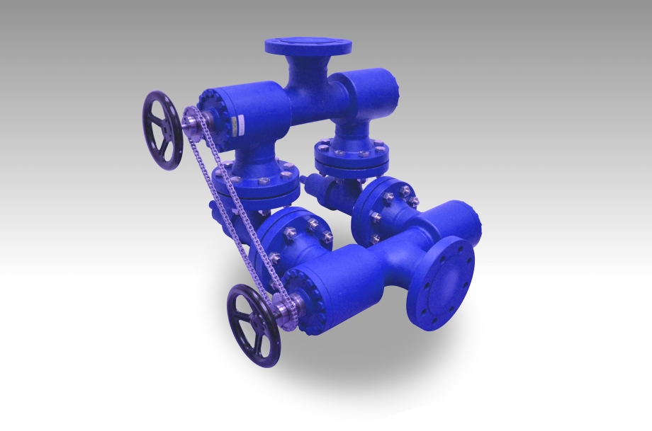
Find check safety valve on Microchek.com. The system is available in a variety of polymers and elastomers to ensure compatibility with most liquids and gases. We can select valves that fall into a specific cracking pressure range if needed. We want the opportunity to help you solve your flow control applications and we can build special configurations. Relief valves are used to hold a fluid circuit or reservoir at a positive or negative pressure. Our staff is available to advise you on your applications. Please ask for a FREE sample that meets your needs. If your design requires a unique configuration, we will be pleased to quote your needs. Related terms include idle control valve location, 2-phase steam relief valve, closet flange check valve, double a relief valve qbj, and consolidated relief valve 1905jc-31-gs. Call us for a FREE check valve sample. 1-800-780-0008 Or fax us at 1-800-622-0002. The Microchek system incorporates this cartridge and a wide selection of end pieces to accommodate most connection requirements. This valve is the heart of our system and has a great design.
Microchek is a company with an expertise in cartridge check valves. Check safety valve related phrases are on Microchek.com. The Microchek valve is a cartridge check valve incorporating an innovative guided poppet design. The Microchek valve has a low pressure drop and can be specified with a wide variety of cracking pressures. Other phrases include closet flange check valve, double a relief valve qbj, idle control valve location, consolidated relief valve 1905jc-31-gs, 2-phase steam relief valve. This vaulve may be used alone or as the central component of the system. We offer competitive pricing and reliability because we are the manufacture. Parts are molded and assembled in the U.S. Look for check safety valve on Microchek.com. The Microchek valve incorporates our innovative check valve module with ultrasonically welded end pieces. Microcheks innovative designs use a minimum number of parts to assure reliability through simplicity. Related phrases are 2-phase steam relief valve, consolidated relief valve 1905jc-31-gs, idle control valve location, closet flange check valve, and double a relief valve qbj. The Microchek valve has a low pressure drop and can be specified with a wide variety of cracking pressures.
Check safety valve is related to Microchek.com. We offer competitive pricing and reliability because we are the manufacture. Parts are molded and assembled in the U.S. Call us for a FREE check valve sample. 1-800-780-0008 Or fax us at 1-800-622-0002. This valve is the heart of our system and has a great design. The Microchek valve is a cartridge check valve incorporating an innovative guided poppet design. Other phrases are closet flange check valve, consolidated relief valve 1905jc-31-gs, double a relief valve qbj, 2-phase steam relief valve, and idle control valve location. We want the opportunity to help you solve your flow control applications and we can build special configurations. We can select valves that fall into a specific cracking pressure range if needed. This vaulve may be used alone or as the central component of the system. Our staff is available to advise you on your applications. Please ask for a FREE sample that meets your needs. Microcheks innovative designs use a minimum number of parts to assure reliability through simplicity. The Microchek valve incorporates our innovative check valve module with ultrasonically welded end pieces.
Pressure relief valve is related to Microchek.com. We offer competitive pricing and reliability because we are the manufacture. Parts are molded and assembled in the U.S. The Microchek system incorporates this cartridge and a wide selection of end pieces to accommodate most connection requirements. The Microchek valve is a cartridge check valve incorporating an innovative guided poppet design. Relief valves are used to hold a fluid circuit or reservoir at a positive or negative pressure. We can select valves that fall into a specific cracking pressure range if needed. The Microchek valve has a low pressure drop and can be specified with a wide variety of cracking pressures.
The Microchek valve is a cartridge check valve incorporating an innovative guided poppet design. Relief valves are used to hold a fluid circuit or reservoir at a positive or negative pressure. We want the opportunity to help you solve your flow control applications and we can build special configurations.

As one of the leading manufacturers of cavity free plug valves and special valves, AZ supplies to production plants in the chemical, petrochemical, pharmaceutical, paper, food industries as well as for nuclear power plants and many other areas. Special valves for highest demands in areas with high operating pressures and aggressive, toxic or abrasive media are designed and developed together with our customers. In the 50 years of the company’s existence, AZ has continuously developed to meet the increasing requirements of customers active around the world and today AZ manufactures internationally on four continents.
TSV Service & Sales, a Division of TRIVACO, offers over 55 years of experience in the Industrial, Commercial and Institutional Industry as mechanical specialty sales engineers and application engineering. As the “Factory Authorized Assembler” of Kunkle Relief Valves for the State of Indiana and western Kentucky. We provide Kunkle Safety Valves to Industrial Distributors and carry a local inventory of Kunkle Safety Valves that we can ship to you or drop ship to your customer.
Everyone is encouraged to call us and schedule a sales call to discuss our FREE survey of safety valves in your plant. This allows us to identify any relief valve installation problems and check to see if the valves are for the application and service. You will receive value from this service by addressing any potential safety issues proactively and not waiting until an unfortunate event occurs to act!
TSV also keeps record of manufacturer’s specifications for Kunkle Valve, Farris, Consolidated, Crosby and more to ensure the accuracy and quality of your valves.
We have certified our shop with The National Board and now hold the following code stamps; VR, UV, V and NB. This enables us to repair Kunkle Valve or ANY other manufacturer’s code stamped safety/relief valve, to new condition, right here in Indianapolis!
Everyone is encouraged to call us and schedule a sales call to discuss our FREE survey of safety valves in your plant. This allows us to identify any relief valve installation problems and check to see if the valves are for the application and service. You will receive value from this service by addressing any potential safety issues proactively and not waiting until an unfortunate event occurs.

We take great pride in supplying valves and tube fittings for automobile industry,Textile,Molds, electric power and other industries, and exports to the countries like United States, Japan, Europe etc. Please be aware that our production lead times depend on specific items and quantities. Our success has been based on our understanding of the demands. That"s Why we always ensure that every order requirements are met.
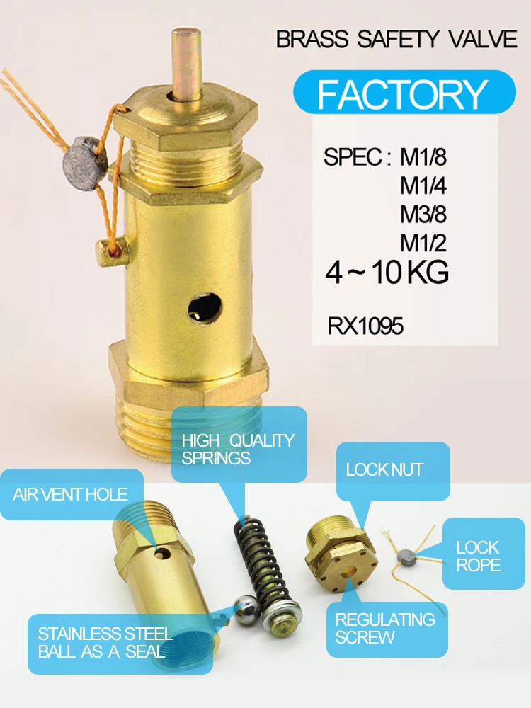
3) For this type of relief valve , we can setting the pressure grade before sales , we can setting 5kg pressure or 8 kg pressure according to your needed .
3) For this type of relief valve , we can setting the pressure grade before sales , we can setting 5kg pressure or 8 kg pressure according to your needed .
3) For this type of relief valve , we can setting the pressure grade before sales , we can setting 5kg pressure or 8 kg pressure according to your needed .
In addition to our cooper parts mainly used in pneumaic and hydraulic fidlds , we have developed pu air tubes ,samll ball valves,quick couplings,ect.RIXIN BRASS FITTING CO.,LTD founded in 1991 . The factory is a private enterprise covering the complete process of design , manufacture,marketing and service.

We take great pride in supplying valves and tube fittings for automobile industry,Textile,Molds, electric power and other industries, and exports to the countries like United States, Japan, Europe etc. Please be aware that our production lead times depend on specific items and quantities. Our success has been based on our understanding of the demands. That"s Why we always ensure that every order requirements are met.
3) For this type of relief valve , we can setting the pressure grade before sales , we can setting 5kg pressure or 8 kg pressure according to your needed .
3) For this type of relief valve , we can setting the pressure grade before sales , we can setting 5kg pressure or 8 kg pressure according to your needed .
3) For this type of relief valve , we can setting the pressure grade before sales , we can setting 5kg pressure or 8 kg pressure according to your needed .
In addition to our cooper parts mainly used in pneumaic and hydraulic fidlds , we have developed pu air tubes ,samll ball valves,quick couplings,ect.RIXIN BRASS FITTING CO.,LTD founded in 1991 . The factory is a private enterprise covering the complete process of design , manufacture,marketing and service.

The primary purpose of a safety valve is to protect life, property and the environment. Safety valves are designed to open and release excess pressure from vessels or equipment and then close again.
The function of safety valves differs depending on the load or main type of the valve. The main types of safety valves are spring-loaded, weight-loaded and controlled safety valves.
Regardless of the type or load, safety valves are set to a specific set pressure at which the medium is discharged in a controlled manner, thus preventing overpressure of the equipment. In dependence of several parameters such as the contained medium, the set pressure is individual for each safety application.
Stainless Steel Safety Relief Valve is a safety mechanism deployed in applications to prevent them from bursting under pressure. Suraj Metal Corporationis a leading manufacturer and supplier of the different types such as the Brass Safety Valveand others in various sizes and dimensions. The valves are fitted with the pipelines in a way that when the pressure goes above the threshold level, the Stainless Steel Air Safety Valveopens up and relieves the system of pressure.
This is important to prevent the pipes from being damaged or bursting under high pressure. The Stainless Steel Safety Exhaust Ball Valveis used in the exhaust systems where the temperature plays major role. When the temperature exceeds certain point, it increases pressure and the safety valve opens and balances the pressure in the system. The spring loaded boiler safety valveis used in boilers and heat exchanger systems where steam and hot water are circulated through pipes. There are different gas safety valvetypes and each of these differ in their purpose and functions. Please feel free to contact us for more information on the different types of air compressor pressure relief valveand others with pricing.
We Keep Bulk Stock of CF8 stainless steel Pressure Safety Valve at our stockyard, contact us for Free Sample & stock list, View Brass Safety Valve Dimension chart
find Stainless Steel Safety Exhaust Ball Valve Dimensions, price list, size chart here, Buy ASTM A351 CF8M 316 temperature safety valve at best price in India
As leaders in sampling valve technology, our zero-defect inline valves can be configured for the most difficult applications where grabbing hazardous chemicals in liquid and gas states, including Hydrofluoric Acid, Fuming Acid and Liquid Chlorine is required. These robust valves, along with our adapters and receptacles, are easy to use and may be customized to your specific needs. We help to maximize operator safety by designing maintenance-free valves that don’t require flushing or purging, thus providing adirectly representative sample, the first time, every time!
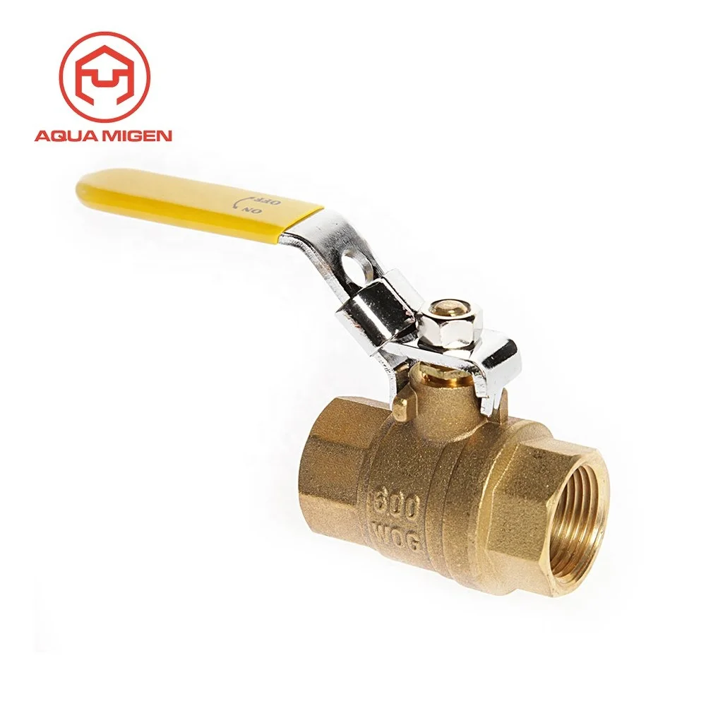
Aball valveis a form of quarter-turnvalvewhich uses a hollow, perforated and pivoting ball to control flow through it. It is open when the ball’s hole is in line with the flow and closed when it is pivoted 90-degrees by the valve handle.The handle lies flat in alignment with the flow when open, and is perpendicular to it when closed, making for easy visual confirmation of the valve’s status.The shut position 1/4 turn could be in either CW or CCW direction. (S = SHUT, O = OPEN)
Ball valves are durable, performing well after many cycles, and reliable, closing securely even after long periods of disuse. These qualities make them an excellent choice for shutoff and control applications, where they are often preferred togatesandglobevalves, but they lack their fine control in throttling applications.
Allkindsofstainlesssteelcasting:include pipe fitting, ball valve, automotiveparts,railroadparts,medicalparts,marineparts,lightingparts,pumpbody,valveparts,architecturalpartsandfurniturepartssoon

In order to ensure that the maximum allowable accumulation pressure of any system or apparatus protected by a safety valve is never exceeded, careful consideration of the safety valve’s position in the system has to be made. As there is such a wide range of applications, there is no absolute rule as to where the valve should be positioned and therefore, every application needs to be treated separately.
A common steam application for a safety valve is to protect process equipment supplied from a pressure reducing station. Two possible arrangements are shown in Figure 9.3.3.
The safety valve can be fitted within the pressure reducing station itself, that is, before the downstream stop valve, as in Figure 9.3.3 (a), or further downstream, nearer the apparatus as in Figure 9.3.3 (b). Fitting the safety valve before the downstream stop valve has the following advantages:
• The safety valve can be tested in-line by shutting down the downstream stop valve without the chance of downstream apparatus being over pressurised, should the safety valve fail under test.
• When setting the PRV under no-load conditions, the operation of the safety valve can be observed, as this condition is most likely to cause ‘simmer’. If this should occur, the PRV pressure can be adjusted to below the safety valve reseat pressure.
Indeed, a separate safety valve may have to be fitted on the inlet to each downstream piece of apparatus, when the PRV supplies several such pieces of apparatus.
• If supplying one piece of apparatus, which has a MAWP pressure less than the PRV supply pressure, the apparatus must be fitted with a safety valve, preferably close-coupled to its steam inlet connection.
• If a PRV is supplying more than one apparatus and the MAWP of any item is less than the PRV supply pressure, either the PRV station must be fitted with a safety valve set at the lowest possible MAWP of the connected apparatus, or each item of affected apparatus must be fitted with a safety valve.
• The safety valve must be located so that the pressure cannot accumulate in the apparatus viaanother route, for example, from a separate steam line or a bypass line.
It could be argued that every installation deserves special consideration when it comes to safety, but the following applications and situations are a little unusual and worth considering:
• Fire - Any pressure vessel should be protected from overpressure in the event of fire. Although a safety valve mounted for operational protection may also offer protection under fire conditions,such cases require special consideration, which is beyond the scope of this text.
• Exothermic applications - These must be fitted with a safety valve close-coupled to the apparatus steam inlet or the body direct. No alternative applies.
• Safety valves used as warning devices - Sometimes, safety valves are fitted to systems as warning devices. They are not required to relieve fault loads but to warn of pressures increasing above normal working pressures for operational reasons only. In these instances, safety valves are set at the warning pressure and only need to be of minimum size. If there is any danger of systems fitted with such a safety valve exceeding their maximum allowable working pressure, they must be protected by additional safety valves in the usual way.
In order to illustrate the importance of the positioning of a safety valve, consider an automatic pump trap (see Block 14) used to remove condensate from a heating vessel. The automatic pump trap (APT), incorporates a mechanical type pump, which uses the motive force of steam to pump the condensate through the return system. The position of the safety valve will depend on the MAWP of the APT and its required motive inlet pressure.
This arrangement is suitable if the pump-trap motive pressure is less than 1.6 bar g (safety valve set pressure of 2 bar g less 0.3 bar blowdown and a 0.1 bar shut-off margin). Since the MAWP of both the APT and the vessel are greater than the safety valve set pressure, a single safety valve would provide suitable protection for the system.
Here, two separate PRV stations are used each with its own safety valve. If the APT internals failed and steam at 4 bar g passed through the APT and into the vessel, safety valve ‘A’ would relieve this pressure and protect the vessel. Safety valve ‘B’ would not lift as the pressure in the APT is still acceptable and below its set pressure.
It should be noted that safety valve ‘A’ is positioned on the downstream side of the temperature control valve; this is done for both safety and operational reasons:
Operation - There is less chance of safety valve ‘A’ simmering during operation in this position,as the pressure is typically lower after the control valve than before it.
Also, note that if the MAWP of the pump-trap were greater than the pressure upstream of PRV ‘A’, it would be permissible to omit safety valve ‘B’ from the system, but safety valve ‘A’ must be sized to take into account the total fault flow through PRV ‘B’ as well as through PRV ‘A’.
A pharmaceutical factory has twelve jacketed pans on the same production floor, all rated with the same MAWP. Where would the safety valve be positioned?
One solution would be to install a safety valve on the inlet to each pan (Figure 9.3.6). In this instance, each safety valve would have to be sized to pass the entire load, in case the PRV failed open whilst the other eleven pans were shut down.
If additional apparatus with a lower MAWP than the pans (for example, a shell and tube heat exchanger) were to be included in the system, it would be necessary to fit an additional safety valve. This safety valve would be set to an appropriate lower set pressure and sized to pass the fault flow through the temperature control valve (see Figure 9.3.8).

A safety valve must always be sized and able to vent any source of steam so that the pressure within the protected apparatus cannot exceed the maximum allowable accumulated pressure (MAAP). This not only means that the valve has to be positioned correctly, but that it is also correctly set. The safety valve must then also be sized correctly, enabling it to pass the required amount of steam at the required pressure under all possible fault conditions.
Once the type of safety valve has been established, along with its set pressure and its position in the system, it is necessary to calculate the required discharge capacity of the valve. Once this is known, the required orifice area and nominal size can be determined using the manufacturer’s specifications.
In order to establish the maximum capacity required, the potential flow through all the relevant branches, upstream of the valve, need to be considered.
In applications where there is more than one possible flow path, the sizing of the safety valve becomes more complicated, as there may be a number of alternative methods of determining its size. Where more than one potential flow path exists, the following alternatives should be considered:
This choice is determined by the risk of two or more devices failing simultaneously. If there is the slightest chance that this may occur, the valve must be sized to allow the combined flows of the failed devices to be discharged. However, where the risk is negligible, cost advantages may dictate that the valve should only be sized on the highest fault flow. The choice of method ultimately lies with the company responsible for insuring the plant.
For example, consider the pressure vessel and automatic pump-trap (APT) system as shown in Figure 9.4.1. The unlikely situation is that both the APT and pressure reducing valve (PRV ‘A’) could fail simultaneously. The discharge capacity of safety valve ‘A’ would either be the fault load of the largest PRV, or alternatively, the combined fault load of both the APT and PRV ‘A’.
This document recommends that where multiple flow paths exist, any relevant safety valve should, at all times, be sized on the possibility that relevant upstream pressure control valves may fail simultaneously.
The supply pressure of this system (Figure 9.4.2) is limited by an upstream safety valve with a set pressure of 11.6 bar g. The fault flow through the PRV can be determined using the steam mass flow equation (Equation 3.21.2):
Once the fault load has been determined, it is usually sufficient to size the safety valve using the manufacturer’s capacity charts. A typical example of a capacity chart is shown in Figure 9.4.3. By knowing the required set pressure and discharge capacity, it is possible to select a suitable nominal size. In this example, the set pressure is 4 bar g and the fault flow is 953 kg/h. A DN32/50 safety valve is required with a capacity of 1 284 kg/h.
Coefficients of discharge are specific to any particular safety valve range and will be approved by the manufacturer. If the valve is independently approved, it is given a ‘certified coefficient of discharge’.
This figure is often derated by further multiplying it by a safety factor 0.9, to give a derated coefficient of discharge. Derated coefficient of discharge is termed Kdr= Kd x 0.9
Critical and sub-critical flow - the flow of gas or vapour through an orifice, such as the flow area of a safety valve, increases as the downstream pressure is decreased. This holds true until the critical pressure is reached, and critical flow is achieved. At this point, any further decrease in the downstream pressure will not result in any further increase in flow.
A relationship (called the critical pressure ratio) exists between the critical pressure and the actual relieving pressure, and, for gases flowing through safety valves, is shown by Equation 9.4.2.
Overpressure - Before sizing, the design overpressure of the valve must be established. It is not permitted to calculate the capacity of the valve at a lower overpressure than that at which the coefficient of discharge was established. It is however, permitted to use a higher overpressure (see Table 9.2.1, Module 9.2, for typical overpressure values). For DIN type full lift (Vollhub) valves, the design lift must be achieved at 5% overpressure, but for sizing purposes, an overpressure value of 10% may be used.
For liquid applications, the overpressure is 10% according to AD-Merkblatt A2, DIN 3320, TRD 421 and ASME, but for non-certified ASME valves, it is quite common for a figure of 25% to be used.
Two-phase flow - When sizing safety valves for boiling liquids (e.g. hot water) consideration must be given to vaporisation (flashing) during discharge. It is assumed that the medium is in liquid state when the safety valve is closed and that, when the safety valve opens, part of the liquid vaporises due to the drop in pressure through the safety valve. The resulting flow is referred to as two-phase flow.
The required flow area has to be calculated for the liquid and vapour components of the discharged fluid. The sum of these two areas is then used to select the appropriate orifice size from the chosen valve range. (see Example 9.4.3)
Many standards do not actually specify sizing formula for two-phase flow and recommend that the manufacturer be contacted directly for advice in these instances.

As the name implies, factory preset switches, regulators, and check valves have been preset and tested in the factory before distribution. This can facilitate your needed flow rates, lower installation time, or be adjusted after assembly.

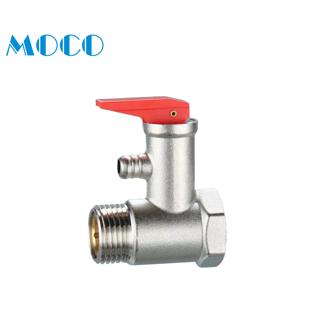
— Pressure safety relief valves are typically used to control pressure on boilers in heating systems, on stored hot water cylinders in domestic hot water systems, and generally in water systems. T&P relief Valve Function:
This is caused by water expanding during the heating cycle. The T/P valve will then relieve pressure by releasing hot water drips to the drain line. It is recommended that an expansion control valve be fitted to the cold water supply line to reduce cold water(not hot water) during the heating cycle expansion, thereby saving energy and increasing the life of the T&P relief valve. Local regulations may require installing an expansion control valve in the cold water supply line.
With so many brass pressure relief valves to choose from, it can be challenging to find the right one. Whether you are looking for a valve that has a higher flow rate or is more durable, here are some essential things to consider when choosing your next brass pressure relief valve:
Once you have answered these questions, you can narrow your search for the perfect brass pressure relief valve. For example, if you have a system that operates at a high PSI, you will need a valve to withstand higher pressures. Conversely, if you have a minor piping system, you may consider a valve with a lower flow rate.
Always read the manufacturer’s instructions carefully before installing, no matter what type of valve you choose. By following these simple guidelines, you can be confident that your new brass pressure relief valve will provide years of reliable service.
Answering these questions will make it easier to narrow your search for the perfect brass pressure relief valve. For example: if you have a more extensive piping system with high operating pressures, you may want to consider one that can handle higher flow rates and has extra features (such as a pilot light). Conversely, if you choose between two valves that can withstand up to 150 PSI but only differ by 0.25 GPM in their flow rate, then maybe select based on price alone. The key here is knowing what factors matter most when purchasing something like this, so don’t be afraid to ask for help from a qualified technician.
Like anything else, it’s essential to read the manufacturer’s instructions carefully before installation. Following these guidelines ensures that your new brass pressure relief valve will provide years of quality service!
Once you have chosen the perfect brass pressure relief valve for your system, it is essential to install it properly. These instructions are based on a typical installation with similar-sized piping and valves. The first step in choosing an appropriate location for installing your new valve will be finding out what type of piping system you currently have.
Once you have determined the pipe size in PSI, it is time to find what pressure relief valve will work with your system. Now that you know the piping system and pipe size, finding a brass pressure relief valve should be as easy as pie!


 8613371530291