
asme safety valve factory
Distributor of hydraulic press safety, quick opening safety, rotary and safety valves. Amerigear®, Boston Gear®, Carlisle®, DeMag®, Desch® and IMI Norgren®, pneumatic, double action, quick release and flow control valves also provided. Repair and preventative maintenance services are offered. Value added services such as custom barcoding, CAD capabilities, OEM assembly, plant surveys and third party logistics are also available. Serves the metal processing, metal service center, paper mill and paper converting, canning, grinding, commercial laundry, marine, oil and gas and material handling industries. Vendor managed inventory (VMI) programs available. Kanban delivery.
Industry leading pressure and safety relief valve designs with over 140 years of technical and application expertise providing custom engineered solutions for O&G, Refining, Chemical, Petrochemical, Process and Power applications. Our designs meet global and local codes and standards (API 526; ASME Section I, IV & VIII; EN ISO 4126; PED & more). Gain insight into the performance of your pressure relief valves with wireless monitoring.
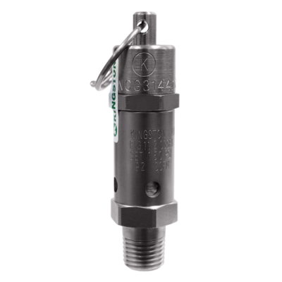
The Kingston Model 110C High Pressure Safety Valve is an ASME Code Certified, precision machined valve with a hard seat. This valve features support for high pressure applications up to 600 psi. It comes equipped with manual test lever and is construction is of cast brass alloy body, machined brass stem with stainless steel ball, seated on a stainless steel base. The Kingston Model 110C High Pressure Safety Valve approved in Massachusetts and Washington DC and is stamped with UV and NB symbols. Registered in all Canadian provinces and territories.
Curtiss-Wright"s selection of Pressure Relief Valves comes from its outstanding product brands Farris and Target Rock. We endeavor to support the whole life cycle of a facility and continuously provide custom products and technologies. Boasting a reputation for producing high quality, durable products, our collection of Pressure Relief Valves is guaranteed to provide effective and reliable pressure relief.
While some basic components and activations in relieving pressure may differ between the specific types of relief valves, each aims to be 100% effective in keeping your equipment running safely. Our current range includes numerous valve types, from flanged to spring-loaded, threaded to wireless, pilot operated, and much more.
A pressure relief valve is a type of safety valve designed to control the pressure in a vessel. It protects the system and keeps the people operating the device safely in an overpressure event or equipment failure.
A pressure relief valve is designed to withstand a maximum allowable working pressure (MAWP). Once an overpressure event occurs in the system, the pressure relief valve detects pressure beyond its design"s specified capability. The pressure relief valve would then discharge the pressurized fluid or gas to flow from an auxiliary passage out of the system.
Below is an example of one of our pilot operated pressure relief valves in action; the cutaway demonstrates when high pressure is released from the system.
Air pressure relief valves can be applied to a variety of environments and equipment. Pressure relief valves are a safety valve used to keep equipment and the operators safe too. They"re instrumental in applications where proper pressure levels are vital for correct and safe operation. Such as oil and gas, power generation like central heating systems, and multi-phase applications in refining and chemical processing.
At Curtiss-Wright, we provide a range of different pressure relief valves based on two primary operations – spring-loaded and pilot operated. Spring-loaded valves can either be conventional spring-loaded or balanced spring-loaded.
Spring-loaded valves are programmed to open and close via a spring mechanism. They open when the pressure reaches an unacceptable level to release the material inside the vessel. It closes automatically when the pressure is released, and it returns to an average operating level. Spring-loaded safety valves rely on the closing force applied by a spring onto the main seating area. They can also be controlled in numerous ways, such as a remote, control panel, and computer program.
Pilot-operated relief valves operate by combining the primary relieving device (main valve) with self-actuated auxiliary pressure relief valves, also known as the pilot control. This pilot control dictates the opening and closing of the main valve and responds to system pressure. System pressure is fed from the inlet into and through the pilot control and ultimately into the main valve"s dome. In normal operating conditions, system pressure will prevent the main valve from opening.
The valves allow media to flow from an auxiliary passage and out of the system once absolute pressure is reached, whether it is a maximum or minimum level.
When the pressure is below the maximum amount, the pressure differential is slightly positive on the piston"s dome size, which keeps the main valve in the closed position. When system pressure rises and reaches the set point, the pilot will cut off flow to the dome, causing depressurization in the piston"s dome side. The pressure differential has reversed, and the piston will rise, opening the main valve, relieving pressure.
When the process pressure decreases to a specific pressure, the pilot closes, the dome is repressurized, and the main valve closes. The main difference between spring-loaded PRVs and pilot-operated is that a pilot-operated safety valve uses pressure to keep the valve closed.
Pilot-operated relief valves are controlled by hand and are typically opened often through a wheel or similar component. The user opens the valve when the gauge signifies that the system pressure is at an unsafe level; once the valve has opened and the pressure has been released, the operator can shut it by hand again.
Increasing pressure helps to maintain the pilot"s seal. Once the setpoint has been reached, the valve opens. This reduces leakage and fugitive emissions.
At set pressure the valve snaps to full lift. This can be quite violent on large pipes with significant pressure. The pressure has to drop below the set pressure in order for the piston to reseat.
At Curtiss-Wright we also provide solutions for pressure relief valve monitoring. Historically, pressure relief valves have been difficult or impossible to monitor. Our SmartPRV features a 2600 Series pressure relief valve accessorized with a wireless position monitor that alerts plant operators during an overpressure event, including the time and duration.
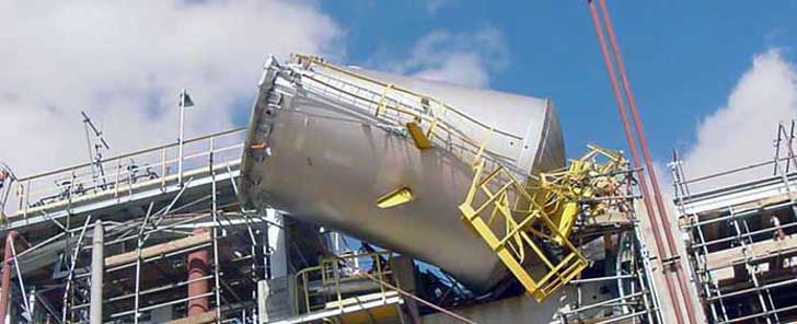
There are many causes of overpressure, but the most common ones are typically blocked discharge in the system, gas blowby, and fire. Even proper inspection and maintenance will not eliminate the occurrence of leakages. An air pressure relief valve is the only way to ensure a safe environment for the device, its surroundings, and operators.
A PRV and PSV are interchangeable, but there is a difference between the two valves. A pressure release valve gradually opens when experiencing pressure, whereas a pressure safety valve opens suddenly when the pressure hits a certain level of over pressurization. Safety valves can be used manually and are typically used for a permanent shutdown. Air pressure relief valves are used for operational requirements, and they gently release the pressure before it hits the maximum high-pressure point and circulates it back into the system.
Pressure relief valves should be subject to an annual test, one per year. The operator is responsible for carrying out the test, which should be done using an air compressor. It’s imperative to ensure pressure relief valves maintain their effectiveness over time and are checked for signs of corrosion and loss of functionality. Air pressure relief valves should also be checked before their installation, after each fire event, and regularly as decided by the operators.
Direct-acting solenoid valves have a direct connection with the opening and closing armature, whereas pilot-operated valves use of the process fluid to assist in piloting the operation of the valve.
A control valve works by varying the rate of fluid passing through the valve itself. As the valve stem moves, it alters the size of the passage and increases, decreases or holds steady the flow. The opening and closing of the valve is altered whenever the controlled process parameter does not reach the set point.
Control valves are usually at floor level or easily accessible via platforms. They are also located on the same equipment or pipeline as the measurement and downstream or flow measurements.
An industrial relief valve is designed to control or limit surges of pressure in a system, most often in fluid or compressed air system valves. It does so as a form of protection for the system and defending against instrument or equipment failure. They are usually present in clean water industries.
A PRV is often referred to as a pressure relief valve, which is also known as a PSV or pressure safety valve. They are used interchangeably throughout the industry depending on company standards.

The Pressure Safety Valve Inspection article provides you information about inspection of pressure safety valve and pressure safety valve test in manufacturing shop as well as in operational plants.
Your pressure safety valve is a direct spring-loaded pressure-relief valve that is opened by the static pressure upstream of the valve and characterized by rapid opening or pop action.
Your construction code for pressure safety valve is API Standard 526 and covers the minimum requirements for design, materials, fabrication, inspection, testing, and commissioning.
These are:API Recommended Practice 520 for Sizing and SelectionAPI Recommended practice 521 Guideline for Pressure Relieving and Depressing SystemsAPI Recommended Practice 527 Seat Tightness of Pressure Relief Valves
For example in the state of Minnesota the ASME Code application and stamping for pressure vessel and boiler is mandatory which “U” and “S” symbols are designated for stamping on the nameplate.
For example if there is pressure vessel need to be installed in the state of Minnesota then the pressure vessel nameplate shall be U stamped and pressure vessel safety valve shall be UV stamped.
National Board Inspection Code (NBIC) have own certification scheme for pressure safety valves and using NB symbol. The NBIC code book for this certification is NB 18.
National Board Inspection Code is assisting ASME organization for ASME UV symbol certification by providing ASME designee in manufactures auditing program.
There are some other standards and codes which are used in pressure safety valve such as:ASME PTC 25 for pressure relief devices which majorly is used for assessment of testing facility and apparatus for safety valvesBS EN ISO 4126-1, 4126-2 and 4126-3 which is construction standard similar to API STD 526.
This API RP 527 might be used in conjunction of API RP 576 as testing procedure for seat tightness testing of pressure safety valve for periodical servicing and inspection.
These are only important points or summery of points for pressure safety valve in-service inspection and should not be assumed as pressure safety valve inspection procedure.
Pressure safety valve inspection procedure is comprehensive document which need to cover inspection methods to be employed, equipment and material to be used, qualification of inspection personnel involved and the sequence of the inspection activities as minimum.
You may use following content as summery of points for Pressure Safety Valve Inspection in operational plantDetermination pressure safety valve inspection interval based API STD 510 and API RP 576 requirementsInspection of inlet and outlet piping after pressure safety valve removal for any foulingInspection of pressure safety valve charge and discharge nozzles for possible deposit and corrosion productsTaking care for proper handling of pressure safety valves from unit to the valve shop. The detail of handling and transportation instruction is provided in API RP 576.Controlling of seals for being intact when the valves arrived to the valve shop.Making as received POP test and recording the relieving pressure.
If the POP pressure is higher than the set pressure the test need to be repeated and if in the second effort it was near to the set pressure it is because of deposit.If in the second effort it was not opened near to the set pressure either it was set wrongly or it was changed during the operationIf the pressure safety valve was not opened in 150% of set pressure it should be considered as stuck shut.If the pressure safety valve was opened below the set pressure the spring is weakenedMaking external visual inspection on pressure safety valve after POP test. The test need contain following item as minimum;the flanges for pitting and roughness
Making body wall thickness measurementDismantling of pressure safety valve if the result of as received POP test was not satisfactoryMaking detail and comprehensive visual and dimensional inspection on the dismantled valve parts (after cleaning)Making special attention to the dismantled valves seating surfaces inspection e.g. disk and seat for roughness, wear and damage which might cause valve leakage in serviceReplacing the damaged parts in dismantled valves based manufacture recommendation and API RP 576 requirementsMaking precise setting of the pressure safety valve after reassembly based manufacture recommendation or NB-18 requirements
Making at least two POP test after setting and making sure the deviation from set pressure is not more than 2 psi for valves with set pressure equal or less than 70 psi or 3% for valves with set pressure higher than 70 psiMaking valve tightness test for leakage purpose after approval of the setting pressure and POP tests. The test method and acceptance criteria must be according to the API RP 576.The API RP 527 also can be used for pressure safety valve tightness test.Recording and maintaining the inspection and testing results.

Taylor Valve Technology® is a manufacturer leader in high-quality industrial valves. We deliver safety relief, high-pressure relief, and back pressure relief valves. Our wide array of choke and control valves and pilot-operated valve products are second to none. Products are designed for demanding industrial needs, meeting quality API and ASME Code requirements. High-demand oil & gas industry, chemical plants, power generators, and the processing industry depend on our valves for consistency and durability. Get effective flow control of liquid, steam, and gas. Valves ship from the Taylor Valve Technology, Inc. United States facility. Delivering worldwide, you can depend on quick turnaround times.

There is a wide range of safety valves available to meet the many different applications and performance criteria demanded by different industries. Furthermore, national standards define many varying types of safety valve.
The ASME standard I and ASME standard VIII for boiler and pressure vessel applications and the ASME/ANSI PTC 25.3 standard for safety valves and relief valves provide the following definition. These standards set performance characteristics as well as defining the different types of safety valves that are used:
ASME I valve - A safety relief valve conforming to the requirements of Section I of the ASME pressure vessel code for boiler applications which will open within 3% overpressure and close within 4%. It will usually feature two blowdown rings, and is identified by a National Board ‘V’ stamp.
ASME VIII valve- A safety relief valve conforming to the requirements of Section VIII of the ASME pressure vessel code for pressure vessel applications which will open within 10% overpressure and close within 7%. Identified by a National Board ‘UV’ stamp.
Full bore safety valve - A safety valve having no protrusions in the bore, and wherein the valve lifts to an extent sufficient for the minimum area at any section, at or below the seat, to become the controlling orifice.
Conventional safety relief valve -The spring housing is vented to the discharge side, hence operational characteristics are directly affected by changes in the backpressure to the valve.
Balanced safety relief valve -A balanced valve incorporates a means of minimising the effect of backpressure on the operational characteristics of the valve.
Pilot operated pressure relief valve -The major relieving device is combined with, and is controlled by, a self-actuated auxiliary pressure relief device.
Power-actuated safety relief valve - A pressure relief valve in which the major pressure relieving device is combined with, and controlled by, a device requiring an external source of energy.
Standard safety valve - A valve which, following opening, reaches the degree of lift necessary for the mass flowrate to be discharged within a pressure rise of not more than 10%. (The valve is characterised by a pop type action and is sometimes known as high lift).
Full lift (Vollhub) safety valve -A safety valve which, after commencement of lift, opens rapidly within a 5% pressure rise up to the full lift as limited by the design. The amount of lift up to the rapid opening (proportional range) shall not be more than 20%.
Direct loaded safety valve -A safety valve in which the opening force underneath the valve disc is opposed by a closing force such as a spring or a weight.
Proportional safety valve - A safety valve which opens more or less steadily in relation to the increase in pressure. Sudden opening within a 10% lift range will not occur without pressure increase. Following opening within a pressure of not more than 10%, these safety valves achieve the lift necessary for the mass flow to be discharged.
Diaphragm safety valve -A direct loaded safety valve wherein linear moving and rotating elements and springs are protected against the effects of the fluid by a diaphragm
Bellows safety valve - A direct loaded safety valve wherein sliding and (partially or fully) rotating elements and springs are protected against the effects of the fluids by a bellows. The bellows may be of such a design that it compensates for influences of backpressure.
Controlled safety valve - Consists of a main valve and a control device. It also includes direct acting safety valves with supplementary loading in which, until the set pressure is reached, an additional force increases the closing force.
Safety valve - A safety valve which automatically, without the assistance of any energy other than that of the fluid concerned, discharges a quantity of the fluid so as to prevent a predetermined safe pressure being exceeded, and which is designed to re-close and prevent further flow of fluid after normal pressure conditions of service have been restored. Note; the valve can be characterised either by pop action (rapid opening) or by opening in proportion (not necessarily linear) to the increase in pressure over the set pressure.
Direct loaded safety valve -A safety valve in which the loading due to the fluid pressure underneath the valve disc is opposed only by a direct mechanical loading device such as a weight, lever and weight, or a spring.
Assisted safety valve -A safety valve which by means of a powered assistance mechanism, may additionally be lifted at a pressure lower than the set pressure and will, even in the event of a failure of the assistance mechanism, comply with all the requirements for safety valves given in the standard.
Supplementary loaded safety valve - A safety valve that has, until the pressure at the inlet to the safety valve reaches the set pressure, an additional force, which increases the sealing force.
Note; this additional force (supplementary load), which may be provided by means of an extraneous power source, is reliably released when the pressure at the inlet of the safety valve reaches the set pressure. The amount of supplementary loading is so arranged that if such supplementary loading is not released, the safety valve will attain its certified discharge capacity at a pressure not greater than 1.1 times the maximum allowable pressure of the equipment to be protected.
Pilot operated safety valve -A safety valve, the operation of which is initiated and controlled by the fluid discharged from a pilot valve, which is itself, a direct loaded safety valve subject to the requirement of the standard.
The common characteristic shared between the definitions of conventional safety valves in the different standards, is that their operational characteristics are affected by any backpressure in the discharge system. It is important to note that the total backpressure is generated from two components; superimposed backpressure and the built-up backpressure:
Subsequently, in a conventional safety valve, only the superimposed backpressure will affect the opening characteristic and set value, but the combined backpressure will alter the blowdown characteristic and re-seat value.
The ASME/ANSI standard makes the further classification that conventional valves have a spring housing that is vented to the discharge side of the valve. If the spring housing is vented to the atmosphere, any superimposed backpressure will still affect the operational characteristics. Thiscan be seen from Figure 9.2.1, which shows schematic diagrams of valves whose spring housings are vented to the discharge side of the valve and to the atmosphere.
By considering the forces acting on the disc (with area AD), it can be seen that the required opening force (equivalent to the product of inlet pressure (PV) and the nozzle area (AN)) is the sum of the spring force (FS) and the force due to the backpressure (PB) acting on the top and bottom of the disc. In the case of a spring housing vented to the discharge side of the valve (an ASME conventional safety relief valve, see Figure 9.2.1 (a)), the required opening force is:
In both cases, if a significant superimposed backpressure exists, its effects on the set pressure need to be considered when designing a safety valve system.
Once the valve starts to open, the effects of built-up backpressure also have to be taken into account. For a conventional safety valve with the spring housing vented to the discharge side of the valve, see Figure 9.2.1 (a), the effect of built-up backpressure can be determined by considering Equation 9.2.1 and by noting that once the valve starts to open, the inlet pressure is the sum of the set pressure, PS, and the overpressure, PO.
Balanced safety valves are those that incorporate a means of eliminating the effects of backpressure. There are two basic designs that can be used to achieve this:
Although there are several variations of the piston valve, they generally consist of a piston type disc whose movement is constrained by a vented guide. The area of the top face of the piston, AP, and the nozzle seat area, AN, are designed to be equal. This means that the effective area of both the top and bottom surfaces of the disc exposed to the backpressure are equal, and therefore any additional forces are balanced. In addition, the spring bonnet is vented such that the top face of the piston is subjected to atmospheric pressure, as shown in Figure 9.2.2.
The bellows arrangement prevents backpressure acting on the upper side of the disc within the area of the bellows. The disc area extending beyond the bellows and the opposing disc area are equal, and so the forces acting on the disc are balanced, and the backpressure has little effect on the valve opening pressure.
Bellows failure is an important concern when using a bellows balanced safety valve, as this may affect the set pressure and capacity of the valve. It is important, therefore, that there is some mechanism for detecting any uncharacteristic fluid flow through the bellows vents. In addition, some bellows balanced safety valves include an auxiliary piston that is used to overcome the effects of backpressure in the case of bellows failure. This type of safety valve is usually only used on critical applications in the oil and petrochemical industries.
Since balanced pressure relief valves are typically more expensive than their unbalanced counterparts, they are commonly only used where high pressure manifolds are unavoidable, or in critical applications where a very precise set pressure or blowdown is required.
This type of safety valve uses the flowing medium itself, through a pilot valve, to apply the closing force on the safety valve disc. The pilot valve is itself a small safety valve.
The diaphragm type is typically only available for low pressure applications and it produces a proportional type action, characteristic of relief valves used in liquid systems. They are therefore of little use in steam systems, consequently, they will not be considered in this text.
The piston type valve consists of a main valve, which uses a piston shaped closing device (or obturator), and an external pilot valve. Figure 9.2.4 shows a diagram of a typical piston type, pilot operated safety valve.
The piston and seating arrangement incorporated in the main valve is designed so that the bottom area of the piston, exposed to the inlet fluid, is less than the area of the top of the piston. As both ends of the piston are exposed to the fluid at the same pressure, this means that under normal system operating conditions, the closing force, resulting from the larger top area, is greater than the inlet force. The resultant downward force therefore holds the piston firmly on its seat.
If the inlet pressure were to rise, the net closing force on the piston also increases, ensuring that a tight shut-off is continually maintained. However, when the inlet pressure reaches the set pressure, the pilot valve will pop open to release the fluid pressure above the piston. With much less fluid pressure acting on the upper surface of the piston, the inlet pressure generates a net upwards force and the piston will leave its seat. This causes the main valve to pop open, allowing the process fluid to be discharged.
When the inlet pressure has been sufficiently reduced, the pilot valve will reclose, preventing the further release of fluid from the top of the piston, thereby re-establishing the net downward force, and causing the piston to reseat.
Pilot operated safety valves offer good overpressure and blowdown performance (a blowdown of 2% is attainable). For this reason, they are used where a narrow margin is required between the set pressure and the system operating pressure. Pilot operated valves are also available in much larger sizes, making them the preferred type of safety valve for larger capacities.
One of the main concerns with pilot operated safety valves is that the small bore, pilot connecting pipes are susceptible to blockage by foreign matter, or due to the collection of condensate in these pipes. This can lead to the failure of the valve, either in the open or closed position, depending on where the blockage occurs.
The terms full lift, high lift and low lift refer to the amount of travel the disc undergoes as it moves from its closed position to the position required to produce the certified discharge capacity, and how this affects the discharge capacity of the valve.
A full lift safety valve is one in which the disc lifts sufficiently, so that the curtain area no longer influences the discharge area. The discharge area, and therefore the capacity of the valve are subsequently determined by the bore area. This occurs when the disc lifts a distance of at least a quarter of the bore diameter. A full lift conventional safety valve is often the best choice for general steam applications.
The disc of a high lift safety valve lifts a distance of at least 1/12th of the bore diameter. This means that the curtain area, and ultimately the position of the disc, determines the discharge area. The discharge capacities of high lift valves tend to be significantly lower than those of full lift valves, and for a given discharge capacity, it is usually possible to select a full lift valve that has a nominal size several times smaller than a corresponding high lift valve, which usually incurs cost advantages.Furthermore, high lift valves tend to be used on compressible fluids where their action is more proportional.
In low lift valves, the disc only lifts a distance of 1/24th of the bore diameter. The discharge area is determined entirely by the position of the disc, and since the disc only lifts a small amount, the capacities tend to be much lower than those of full or high lift valves.
Except when safety valves are discharging, the only parts that are wetted by the process fluid are the inlet tract (nozzle) and the disc. Since safety valves operate infrequently under normal conditions, all other components can be manufactured from standard materials for most applications. There are however several exceptions, in which case, special materials have to be used, these include:
Cast steel -Commonly used on higher pressure valves (up to 40 bar g). Process type valves are usually made from a cast steel body with an austenitic full nozzle type construction.
For all safety valves, it is important that moving parts, particularly the spindle and guides are made from materials that will not easily degrade or corrode. As seats and discs are constantly in contact with the process fluid, they must be able to resist the effects of erosion and corrosion.
The spring is a critical element of the safety valve and must provide reliable performance within the required parameters. Standard safety valves will typically use carbon steel for moderate temperatures. Tungsten steel is used for higher temperature, non-corrosive applications, and stainless steel is used for corrosive or clean steam duty. For sour gas and high temperature applications, often special materials such as monel, hastelloy and ‘inconel’ are used.
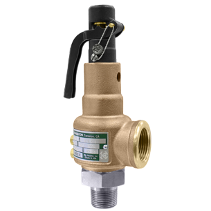
Standard safety valves are generally fitted with an easing lever, which enables the valve to be lifted manually in order to ensure that it is operational at pressures in excess of 75% of set pressure. This is usually done as part of routine safety checks, or during maintenance to prevent seizing. The fitting of a lever is usually a requirement of national standards and insurance companies for steam and hot water applications. For example, the ASME Boiler and Pressure Vessel Code states that pressure relief valves must be fitted with a lever if they are to be used on air, water over 60°C, and steam.
A test gag (Figure 9.2.7) may be used to prevent the valve from opening at the set pressure during hydraulic testing when commissioning a system. Once tested, the gag screw is removed and replaced with a short blanking plug before the valve is placed in service.
The amount of fluid depends on the particular design of safety valve. If emission of this fluid into the atmosphere is acceptable, the spring housing may be vented to the atmosphere – an open bonnet. This is usually advantageous when the safety valve is used on high temperature fluids or for boiler applications as, otherwise, high temperatures can relax the spring, altering the set pressure of the valve. However, using an open bonnet exposes the valve spring and internals to environmental conditions, which can lead to damage and corrosion of the spring.
When the fluid must be completely contained by the safety valve (and the discharge system), it is necessary to use a closed bonnet, which is not vented to the atmosphere. This type of spring enclosure is almost universally used for small screwed valves and, it is becoming increasingly common on many valve ranges since, particularly on steam, discharge of the fluid could be hazardous to personnel.
Some safety valves, most commonly those used for water applications, incorporate a flexible diaphragm or bellows to isolate the safety valve spring and upper chamber from the process fluid, (see Figure 9.2.9).

When it comes to understanding pressure relief valve testing requirements, there’s a lot of information out there, but not all of it seems conclusive. If you’re new to pressure relief valves or are getting started in a new industry, it can be tough to decipher what testing requirements your facility needs to meet.
It’s good to keep in mind that every industry and region has unique pressure relief valve testing requirements. Your facility may be required to just bench test pressure relief valves every five years, or you may have to test valves every year, but bench test and repair valves every three to five years. There is a large variance in the testing requirements for pressure relief and safety valves depending on your industry and your region. That said, there are a few general testing requirements we can look at to start with.
The National Board Inspection Code, created by the National Board of Boiler and Pressure Valve Inspectors, makes the following recommendations on the frequency of testing for safety and pressure relief valves, depending on the temperature, psi, and function of your boiler:
It’s important to remember that these are general pressure valve testing recommendations. For specific requirements, you’ll have to verify your unique jurisdictional and industry code requirements. See the resources below for more information.
The National Board Inspection Code is an industry-recognized name offering quality information on pressure relief valve testing requirements. Here, you’ll find a wealth of information and testing best practices.
The ASME is another organization setting pressure relief valve testing requirements, and offering the necessary training engineers need to test and understand the testing procedures for pressure relief valves. In addition to testing requirements and standards, the ASME offers a variety of online courses on pressure relief valves, from fabrication and proper installation to inspection and repair.
For specific testing standards, it’s best to check with your industry and your regional jurisdiction. Pressure relief valve testing requirements can vary by state or region and are most often industry-specific. Check your industry’s standards, and check local code requirements to ensure your facility is adhering to the most relevant pressure relief valve testing requirements.
When you’re looking for the pressure relief valve testing requirements relevant to your facility, it’s important to understand the different testing methods that are available to you. It’s likely that regardless of your industry if you have safety and pressure relief valves in use at your facility, you’ll have to bench test those valves at least every five years.
In addition to those bench tests, though, you’ll also have to perform manual or on-site pressure relief valve testing. Here’s a quick look at the three most common pressure relief valve testing methods you’ll see when researching pressure relief valve testing requirements:
The most commonly mandated form of pressure relief valve testing, bench testing is unique in that it requires you completely shut down your facility’s system and remove all pressure relief valves. The valves are then transported to a lab where they are tested and repaired as necessary. Tested valves are then re-installed in your system.
Bench testing is the most involved method of pressure relief valve testing, but as this is how valves are tested when they’re manufactured, the industry considers this to be the most thorough testing method.
Inline testing is another accurate pressure relief valve testing method that doesn’t require the removal of valves or facility downtime. With inline safety relief valve testing equipment, a trained technician can test valves in the system to calculate the real setpoint of a valve in the system.
While inline testing cannot take the place of mandated bench testing, it is a more efficient form of testing for other regular testing requirements. Inline pressure relief valve testing is the ideal choice for any required testing that does not have to be bench testing, as it eliminates the need for downtime while still providing exceptionally accurate results.
Some pressure relief valve testing requirements will call for regular manual testing for freedom of operation. This is a basic test that can be done on-site. To complete an operated-in-place test, the test lever on the valve is manually activated. This test functions to ensure that the valve can open and shut tightly, but it does not verify at what pressure the valve opens and shuts. This is a test that may be required quarterly or bi-annually, to ensure the most basic functionality of safety relief valves.
Pressure relief valve testing is necessary for any facility with safety relief and pressure relief valves. For more information about the equipment you need for pressure relief valve testing, the profitability of certain testing methods, and more, head to the AccuTEST blog. There, you’ll find a variety of resources on everything from implementing inline safety relief valve testing to minimizing plant downtime.
If your company requires regular pressure relief valve testing, you might be interested in AccuTEST’s high-tech equipment. Offering inline testing with accurate, repeatable results, our system is the best on the market. See how our equipment works in real-time — schedule a live webinar demo today.

With more than 1,050 employees and 130,000 safety valves produced per year, LESER is the largest manufacturer of safety valves in Europe and one of the leading companies in its industry worldwide.
LESER offers spring loaded and pilot operated safety valves for all industrial applications according to the Pressure Equipment Directive and ASME XIII. Major companies in the chemical, oil and gas, petrochemical, energy, technical gases, LNG/LPG, pharmaceutical, food and beverage, shipbuilding and heating and air conditioning industries use LESER safety valves.
LESER safety valves are developed for the international market in Hamburg and manufactured in the modern plant in Hohenwestedt/Germany. In addition, LESER produces safety valves to the same standards in India and China for the local markets. Nine subsidiaries and offices in Europe, America, the Middle East and Asia as well as authorized contacts in over 80 countries guarantee competent customer advice and fast, reliable deliveries.


 8613371530291