
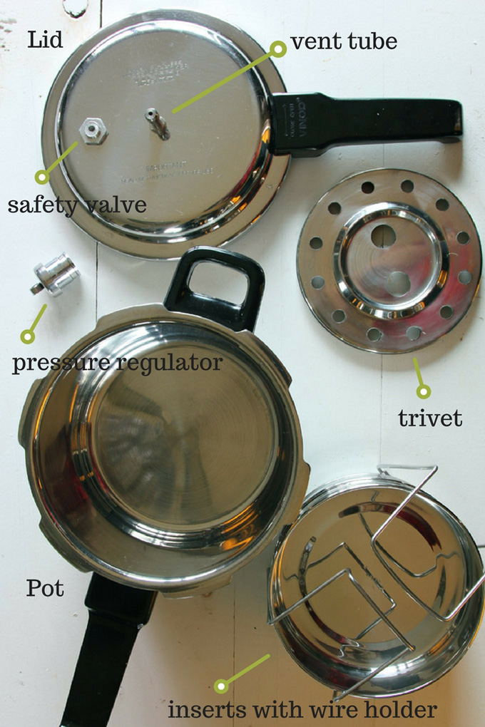
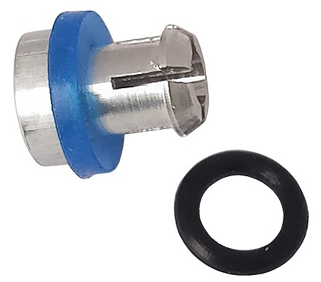
cooker safety valve free sample
Such a valve assembly is known from German laying-open print DOS No. 2,606,676. The pressure relief means thereof consists of a check valve which also serves as a safety valve. It has a valve housing of a resilient material which is fitted into a hole in the cover in the vicinity of the cooking valve aperture. The closure body is designed as a shaft-shaped valve body, transverses the valve opening and supports two spaced valve disks inside the cover as well as a dome-shaped head outside the cover. The head abuts against the valve opening in the pressureless state. As the pressure builds up in the pressure-cooker, however, the valve body is lifted and the upper valve disk closes off the valve opening internally so that the pressure in the cooker can build up. When the pressure becomes excessive, the upper valve disk can move outwardly through the valve opening of the valve housing. This allows steam to escape through the valve opening. The second valve disk preventing the valve body from being blown off the cooker although it does not obstruct the escape of steam. The cooking valve usually comprises a spring-loaded valve and a displaceable pressure indicator for the cooker which is located therein and is also spring-loaded. The springs press against the interior of a cap which is adapted to be screwed on to the valve housing. In the known valve assembly, the cap of the cooking valve has an asymmetrical design on the underside facing towards the cooker cover. It features a guide bevel at this location which reduces its clearance height. In the normal cooking position, the area with the maximum inner clearance height overlaps or overlies the check valve. When the cap is screwed off, the area with a minimum clearance height comes to lie above the check valve over which it can move without obstruction when the head of the check valve abuts against the outer side of the valve seat in the completely pressureless state. If the check valve has closed due to the internal build-up of pressure in the cooker, ie if the upper valve disk abuts against the valve seat, the guide bevel presses the valve body of the check valve downwardly and steam can escape through the check valve. The pressure in the cooker is relieved, whilst the person using the cooker is warned simultaneously by the sound of the escaping steam not to unscrew the cap any farther. If the valve body has been raised only slightly owing to a slight superpressure in the cooker, eg at the onset of pressure build-up, an additional stop which projects into the clearance height prevents the cap from being rotated any farther.
The known valve assembly is expensive to manufacture, since it requires a valve housing and a valve body for the pressure relief means. These parts are expensive to manufacture and to assemble. The cap of the cooking valve is also expensive to produce owing to its asymmetrical shape, and the dimensions of the guide bevel as well as the region of reduced clearance height must be kept within a narrow tolerance range: the valve body must be pressed downwardly to open the valve on the one hand, although on the othe hand this must not be so far that the valve head closes the opening externally. Another drawback is that when the cap is rotated into the open position, the stop jams the head of the valve body and this cannot return to its original position, even when the cooker is not under pressure, until the cap has been turned back somewhat. When the check valve functions as a safety valve, the valve disk cannot automatically turn back any longer due to the valve opening. The cap cannot be screwed off over the projecting valve body either. This makes it impossible to gain access to the valve body and return it to the normal position. Yet another disadvantage is that the valve body of the check valve can only be cleaned thoroughly--quite essential for proper sealing--if it has been snapped out of the valve disk. Since this is complicated and troublesome, such cleaning is frequently postponed or forgotten completely.
A valve assembly comprising a pressure relief means disposed adjacent to the cooking valve is also known from German utility model No. 7,624,730. The pressure relief means is designed as a safety valve in the form of a check valve. The cap of the cooking valve has indents on the periphery thereof. Both valves are spatially associated with one another such that the valve body can be raised adjacent to such an indent only when the cap is in certain positions. The check valve can be closed and pressure built up in the cooker only in this position. When the valve body is in the raised position, ie when pressure has built up in the cooker, the valve body in turn locks the cap of the cooking valve which cannot be rotated. Hence, the vent opening cannot be opened by adjusting the cap. This known valve assembly, which therefore does not correspond to the preamble of the present invention, is expensive to manufacture due to the design of the check valve. It is also difficult to clean, since the steam is dissipated to one side through a cavity in the cooking valve beneath the cap when the safety valve responds to excessive pressure. These cavities are difficult to reach, even after the cap has been removed. Furthermore, the valve body cannot be turned back into its original position until after the safety valve has responded and the excess pressure has been vented off. Only then can the cap be removed from the cooking valve.
The object of the present invention is to provide a valve assembly according to the preamble of the claim which is economical to manufacture, easy to clean and simple to operate in all modes of operation.
The construction of the closure body as a seal disposed on the cap makes it possible to design the vent opening in the form of a simple hole in the cover without any valve housing. Such a hole can be produced during one and the same operation as the hole for the cooking valve. It is easy to clean. The arrangement of the associated seal in the cap gives rise to a constructional design which is simple and easy to clean. This construction of the pressure relief means is made possible by the recognition that the vent opening need only be open to relieve the pressure. An open valve is unnecessary prior to a pressure build-up, since the air being heated up can escape by way of the conventional sealing rings between the pressure-cooker and the cover until the sealing ring abuts sealingly against the cover and cooker wall due to the build-up of pressure. In the pressure relief means in accordance with the invention, the co-operation of the seal and the vent opening permits steam to escape even when the cap is moved minimally towards the venting position. The pressure in the cooker decreases immediately. Moreover, the co-action of the venting opening and the seal generates a warning sound which warns the cook not to opening the cooking valve while the cooker is still under pressure. If there is no seal in the cap, no pressure will build up in the cooker at all.
The seal can advantageously consist of a material which is so resilient that it sealingly closes the vent opening at normal cooking pressure and permits pressure to be vented should it become eccessive. The pressure relief means thus functions as a safety valve as well.
The annular seal advantageously has an internal diameter which is smaller than the external diameter of the cap section it surrounds. The annular seal is thus seated in the cap region in such a way that it can be neither twisted nor lost. Dirt cannot readily collect between the cap and the annular seal so that the seal does not have to be removed every time the cooker is cleaned.
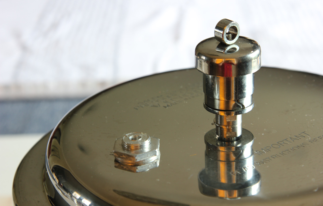
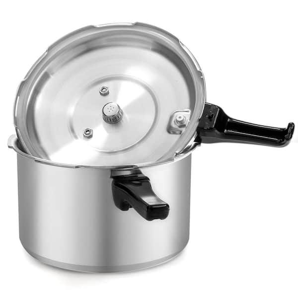
FIG. 1 indicates the cover 1 of a pressure-cooker. A valve housing 2 is firmly riveted into place in the cover 1. It includes a valve seat 2a against which a valve body 3 is urged by a valve spring 4. This valve spring 4 presses against the inner side of a cap 5 overlying the entire valve assembly and designed as a cap or acorn nut. A pressure indicator 6 is displaceably mounted in the valve body 3. It is pre-biased by a pressure indicator spring 7 which presses against the valve body on the one hand and, on the other hand, against the inside of the cap 5. The cap 5 is adapted to be screwed on to the valve housing by means of a thread 8, thereby determining the tension of the valve and pressure indicator springs.
The cover 1 has a hole 10 in spaced relation from the valve axis and is located between the internal and external diameters of the annular seal. It serves as a vent opening and is closed by the annular seal 9 during cooking.
The afore-described valve assembly functions as follows during cooking: the cap 5 is screwed down to the stop with the inscription "cooking" adjacent to the arrow 12. The valve spring as well as the pressure indicator spring are both pre-biased in this position. The annular seal 9 closes the hole 10. Steam pressure can now build up in the cooker in the known manner once the warm air has escaped between the cooker and the cover as mentioned above. The cooking pressure is chosen by regulating the supply of heat in response to the position of the pressure indicator 6. At the conclusion of cooking, the cap 5 is turned half a turn to the "venting" position. This causes the annular seal to release the hole 10, the steam can escape and the pressure is relieved. The venting is continuous and dependent on the speed of rotation.
If the pressure indicator is not observed during cooking, i.e. if the supply of heat is not turned down at the proper time, thus causing the pressure in the cooker to become excessive, the steam can escape through the hole 10. This gives off a warning whistle and deforms the annular seal 9. Should the generated steam still be excessively high, the valve body 3 is lifted off its seat 2a.
That ensures that nothing interferes with the lid of the pressure cooker, which is where most of the other safety systems are. Also, check that the primary valve is clean and clear before pressure cooking.
If something were to go side-ways, even before it gets to that point, the pressure cooker itself will detect that the pressure (temperature) inside is too high and turn off the pressure cooker. But, while that’s happening, though, the food inside is still boiling and building pressure so the cooker will release excess pressure from the valve on the lid. And, if the main valve were to be clogged the cooker will release pressure from the lid-lock or secondary valve. If that were to be blocked, the cooker will release pressure from the gasket.
The last safety system of for absent-minded cooks like me. Where at the last minute I realize, “Oh, I need to add some carrots” and try to open the pressure cooker during cooking. Well, the lid locks automatically the minute pressure starts to build. It means that if there is any pressure still inside the cooker, you cannot open the lid. It’s a mechanical system so even if there is no electricity you will still be prevented from opening the lid.

The present invention relates to an air relief valve and, in particular, to an air relief valve structure of a pressure cooker that allows food materials to be discharged from an air relief hole to prevent the food material from clogging the pressure cooker and reducing the relief pressure of the pressure cooker.
As civilization, science and technology advance, various modern products are introduced into our life. As to dining, people cooked rice and food by burning wood in the past, and started using products such as electronic cookers or electric cookers after electricity and gas are invented or discovered. However, some still use gas for cooking rice or other food. However, the oil price keeps increasing recently, and the price of some of the daily necessary materials also increases. Of course, these daily necessary materials also include the indispensable resources or energies such as water, electricity and gas. When the aforementioned resources or energies are used, the power saving issue is also taken into consideration to save costs and family expenses. In the age of an increased price of daily necessities and energies, related manufacturers spare no effort to develop products with the features of power saving and carbon reduction and of overcoming environmental issues. Among the aforementioned cooking devices, the electric cookers and electronic cookers for cooking food and rice are necessary electric appliances. The longer the cooking time, the greater the energy consumption. Therefore, it is a main subject for related manufacturers to develop a cooking device that can cook food or rice quickly.
Pressure cookers available in the market can overcome the aforementioned problem. The basic structure of a general pressure cooker includes a steel airtight container combined with a pressure relief valve. At a higher pressure, the boiling point of liquid increases. Based on this physical phenomenon, the pressure cooker can apply pressure to water, such that the water can reach a higher temperature without boiling to expedite the cooking of food, to achieve the effect of saving time and energy.
However, most conventional pressure relief valves used in a pressure cooker can be used simply for discharging gas to reduce the pressure in the pressure cooker. If the air relief hole is clogged by food materials, then, the purpose of relieving pressure cannot be achieved quickly and effectively. The pressure relief valve fails to discharge gas quickly and effectively mainly due to the too-small air relief hole. As a result, a small amount of food debris may occupy the whole pressure relief space easily and cause the failure of relieving the pressure.
Therefore, it is a primary objective of the present invention to provide an air relief valve structure of a pressure cooker that allows food materials to be discharged from an air relief hole to prevent the food material from clogging the pressure cooker and reducing the relief pressure of the pressure cooker.
To achieve the aforementioned objective, the present invention provides an air relief valve structure of a pressure cooker, and the pressure cooker comprises a cooker body and a lid covered onto the top of the cooker body. The lid has a containing trough, and the air relief valve is installed at the containing trough. The air relief valve includes a middle column having a containing space formed in the middle column and at least one air relief hole and a through hole on an outer wall of the middle column and interconnected to the containing space. An airtight column is installed in the middle column, and has an end column defined at an end of the airtight column and disposed adjacent to an inner wall of the middle column. The end column has a diameter equal to the diameter of the containing space of the middle column. An elastic element is sheathed on the airtight column and abuts the end column. A gravity valve is installed at the top of the middle column and is coupled to the airtight column.
According to a preferred embodiment of the present invention, the air relief valve structure of a pressure cooker further comprises a rubber ring sheathed on the end column and abutted against an inner wall of the middle column.
According to a preferred embodiment of the present invention, the gravity valve has a bevel defined on an inner wall of the gravity valve, with a buffer portion extended inwardly from an end of the gravity valve.
FIG. 1 is a perspective view of an air relief valve installed to a pressure cooker in accordance with a preferred embodiment of the present invention;
With reference to FIGS. 1 to 3 for an air relief valve structure of a pressure cooker in accordance with the present invention, the pressure cooker 1 comprises a cooker body 10 and a lid 12 covered onto the top of the cooker body 10. The lid 12 has a containing trough 120 formed therein, and an air relief valve 2 is installed at the containing trough 120. The air relief valve 2 includes a middle column 20 having a containing space 201 and at least one air relief hole 202 and a through hole 203 formed on an outer wall of the middle column 20 and interconnected with the containing space 201. An airtight column 21 is installed in the containing space 201, and has an end column 210 defined at an end of the airtight column 21 and disposed adjacent to an inner wall of the middle column 20 and the other end passing through the through hole 203. The end column 210 has a diameter equal to the diameter of the containing space 201 of the middle column 20. An elastic element 22 is sheathed on the airtight column 21 and abuts against the end column 210. A gravity valve 23 is installed at a top end of the middle column 20 and is coupled to the airtight column 21. In addition, a rubber ring 24 is sheathed on the end column 210 and abuts against an inner wall of the middle column 20. A bevel 230 is defined at an inner wall of the gravity valve 23, and a buffer portion 232 is extended inwardly from an end of the gravity valve 23.
With reference to FIGS. 4 and 5, the end column 210 of the airtight column 21 will shelter the air relief hole 202 completely, if the pressure in the pressure cooker 1 (as shown in FIG. 1) is smaller than a predetermined total number of kilograms of the elastic element 22 and the gravity valve 23. The air relief hole 202 will have a gap (which is a general pressure relief mode at a normal use of the pressure cooker 1), if the pressure in the pressure cooker 1 exceeds the predetermined total number of kilograms.
On the other hand, if the pressure cooker is used improperly, food materials and an incorrect water level may result in the gap being clogged by the food debris and a rapid increase of pressure in the pressure cooker 1. Under such effect, the length of the elastic element 22 is compressed significantly. An end of the elastic element 22 abuts the end column 210, and the other end of the elastic element 22 abuts the inner wall at the top of the middle column 20. Thus, the air relief hole 202 covered by the end column 210 is exposed to discharge the clogged food material successfully. In addition, a gap is produced between the inner wall of the middle column 20 and the outer wall of the end column 210, so that the rubber ring 24 is provided for enhancing the overall sealing effect and preventing pressure leakage.
In the meantime, the pressure in the pressure cooker 1 drops rapidly, and the action force of the elastic element 22 pushes the airtight column 21 to resume its original position after the pressure drops. Thus, the end column 210 covers the air relief hole 202 again, and the pressure starts accumulating from the beginning again. The regulation of this effect can maintain the ratio of the water level and the food within a normal range continuously to discharge the food material or soup to the containing trough 120 at the top of the lid 12. To prevent liquid, gas and food from spilling out during the pressure relief process, a bevel 230 is defined at the inner wall of the gravity valve 23, and a buffer portion 232 is extended inwardly from an end of the gravity valve 23. If liquid, gas or food spills, they will slide down along the bevel 230. While sliding down, the liquid, gas and food is buffered by the buffer portion 232 to prevent them from being spilled over messily.
Compared with the conventional air relief valve structure of a pressure cooker, the pressure cooker of the present invention can achieve the effect of discharging food debris by the air relief hole with a greater diameter (which is equal to the width of the end column) to relieve pressure quickly.
Quick pressure release or natural pressure release?It’s one of the most common questions I get. Electric pressure cookers and multi-cookers like the Instant Pot, Ninja Foodi, and Crockpot Express have the ability to release pressure two ways. Instant Pot Natural Release is a frequent search term. Let me explain the difference!
Releasing the pressure can be a little intimidating to people who are new to pressure cooking—especially the quick release with the noise and jet of steam. But don’t let a little noise get between you and fabulous meals cooked in your pressure cooker!
Those are often the first questions new pressure cooker users ask. So I thought it would be a perfect time for a post explaining it for all those who have an electric pressure cooker or multi-cooker like the Instant Pot waiting for them under the tree.
When the cook time ends, your pressure cooker will beep. At this point, the recipe will direct you to release the pressure in the cooking pot. You can release the pressure two ways: a quick pressure release or a natural pressure release.
A quick pressure release is when you turn the pressure release switch to the Venting position and let the steam to release quickly when the cook time ends. This will result in a strong jet of steam coming from the pressure release valve. This is normal.If drops of liquid or foam start to emerge from the pressure release valve, simply switch the valve back to the Sealed position and use an Intermittent Pressure Release (more on that below).
Other pressure cookers may have different labels, but it’s the same basic principle. Turn the valve to allow the steam to escape / pressure to release.
When the pressure is fully released, the float valve will drop and the lid will unlock to open. For safety reasons, the pressure cooker will not open until the pressure is released and the float valve has dropped.
A natural pressure release is when you leave the pressure release switch in the Sealed position when the cook time ends. This lets the pressure release slowly, without you doing anything. When the pressure is fully released, the float valve will drop and the lid will unlock and open.
A natural pressure release is a bit anticlimactic in comparison to a quick pressure release. There is no jet of steam when the natural pressure release starts. There’s also no clear way to tell when the pressure is fully released, and no beep or signal when the lid unlocks. Sometimes you can hear the float valve drop if you’re close by.
The time it takes for the pressure to release naturally will vary depending on the ingredients and amount of liquid in the pressure cooker. A natural pressure release can take from 5 to 30 minutes in the electric pressure cooker.
Using a natural pressure release allows the cooking to stop gradually. You don’t want to open the valve quickly when the ingredients inside could be foaming. You’ll get foam shooting out through the valve, so use a natural pressure release when making steel cut oats, a large pot of soup or pasta.
With this method, you open and close the pressure release valve in short intervals. This allows the pressure to escape more quickly than a natural pressure release and also prevents foam from coming out of the pressure release valve.
With some foods, one or two closed intervals is all I need before I can leave the valve in the Venting position; with other foods, if the foaming is particularly bad, I will close the valve and wait a minute or two, then slide the valve to Venting again and continue opening and closing the valve as needed.
No you do not need to turn the pressure cooker off for a quick or natural pressure release. The pressure will release on the Keep Warm setting. The benefit of not turning it off is that the time will count up so you can see how long it’s been since the pressure cooking time ended.
I prefer to turn off or unplug the pressure cooker before I do a quick pressure release or natural pressure release. I seem to always forget to turn off the pressure cooker if I don’t turn it off when the pressure cooking ends. I also prefer to set a timer to remind me 10 minutes has passed and it’s time to release the pressure when I’m doing a natural pressure release.
Once you have your first meal under your belt, move on to some easy pressure cooking recipes. Before you know it, you’ll be making fabulous pressure cooker meals and wondering how you ever cooked without it.

Safety valves and pressure relief valves are crucial for one main reason: safety. This means safety for the plant and equipment as well as safety for plant personnel and the surrounding environment.
Safety valves and pressure relief valves protect vessels, piping systems, and equipment from overpressure, which, if unchecked, can not only damage a system but potentially cause an explosion. Because these valves play such an important role, it’s absolutely essential that the right valve is used every time.
The valve size must correspond to the size of the inlet and discharge piping. The National Board specifies that the both the inlet piping and the discharge piping connected to the valve must be at least as large as the inlet/discharge opening on the valve itself.
The connection types are also important. For example, is the connection male or female? Flanged? All of these factors help determine which valve to use.
The set pressure of the valve must not exceed the maximum allowable working pressure (MAWP) of the boiler or other vessel. What this means is that the valve must open at or below the MAWP of the equipment. In turn, the MAWP of the equipment should be at least 10% greater than the highest expected operating pressure under normal circumstances.
Temperature affects the volume and viscosity of the gas or liquid flowing through the system. Temperature also helps determine the ideal material of construction for the valve. For example, steel valves can handle higher operating temperatures than valves made of either bronze or iron. Both the operating and the relieving temperature must be taken into account.
Back pressure, which may be constant or variable, is pressure on the outlet side of the pressure relief valve as a result of the pressure in the discharge system. It can affect the set pressure of the upstream valve and cause it to pop open repeatedly, which can damage the valve.
For installations with variable back pressure, valves should be selected so that the back pressure doesn’t exceed 10% of the valve set pressure. For installations with high levels of constant back pressure, a bellows-sealed valve or pilot-operated valve may be required.
Different types of service (steam, air, gas, etc.) require different valves. In addition, the valve material of construction needs to be appropriate for the service. For example, valves made of stainless steel are preferable for corrosive media.
Safety valves and relief valves must be able to relieve pressure at a certain capacity. The required capacity is determined by several factors including the geometry of the valve, the temperature of the media, and the relief discharge area.
These are just the basic factors that must be considered when selecting and sizing safety valves and relief valves. You must also consider the physical dimensions of the equipment and the plant, as well as other factors related to the environment in which the valve will operate.
Take another example. You’re a teenager, you’ve had lots of unsettling and unpleasant experiences, and high school is something like hell. Your mind is a very dark and tumultuous place and, without really being able to explain to yourself why, you find that only cutting yourself with a razor blade helps you release that pressure. Probably you don’t exactly call it “pressure”—but if you did, and if you had a way to release that mind pressure in some way other than cutting yourself, can you see that you might gain the same relief in a better way? Cutting yourself is a too-literal safety valve: wouldn’t a figurative safety valve serve you better?
Forget for a moment about the exact content of our thoughts in those three situations—thoughts like, perhaps, “Wow, she is so sexy!”, “I hate my life so much!” or “I think I’ll build a boat by hand and sail around the world!” A cognitive therapist might want to focus on those words; but who will help you focus on the pressure you’re feeling? That must be you. Just as you must install windows in your mind and open them regularly, it is your job to install a safety valve that you know how to operate and that actually releases what for many of us is relentless and often intolerable pressure.
Your mind is a pressure cooker. Therefore you must create a release valve. That release valve might be as simple as creating and using a mantra like “releasing pressure now,” creating and using a more complicated ceremonial safety valve that involves letting the pressure out through your mouth with a “whoosh!”, or creating and using some unique and idiosyncratic strategy that you dream up. If you don’t create this release valve and if you don’t use it regularly, you will live under that pressure and do things to relieve that pressure that you don’t really want do, like betraying your loved ones, cutting yourself, or racing around in existential despair.
I hope that you see clearly what your second task is. Last week I advised you to add windows to your mind and regularly open them. That is your first task. Now I would like you to create a safety valve that allows you to release all that relentless, recurring mind pressure in smart, safe ways. When you can do that releasing you will likely cure your mania, your obsessive-compulsive disorder, your addictive behaviors, and all the other consequences that result from not releasing mind pressure soon enough or well enough. When you begin to do this, you will have taken another step on the path to self-mastery.


 8613371530291