
safety valve 2-point reduction made in china
HEROSE cryogenic safety valves are certified to global certifications for CN, TR CU and ASME. Thus they can be used worldwide, regardless of where the system is installed later. Cryogenic safety valves are available in sizes from DN6 to DN50 and secure pressures up to 550 bar, at operating temperatures of -270°C to +400°C. The safety valves are manufactured primarily in stainless steel but also in bronze and brass.
Please find the cryogenic safety valves in the product choice below. You can combine different product characteristicsto find your cryogenic safety valve better.

Because of different of drive source, SSV can dividedinto Hydraulic safety valve and pneumatic valve ; With thermal and high voltage explosion-proof device ; Actuators and prepare two parts of the valve, standard interface, easy replacement and maintenance .
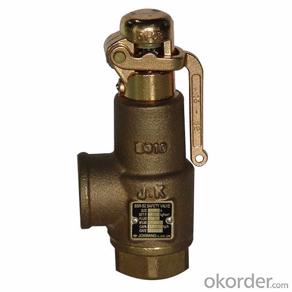
This valve is used for power plant boilers, pressure containers, pressure and temperature reducing device and other facilities. It serves to prevent the pressure exceeding the highest allowable pres-sure value and ensure the safety of the device when working.
(1)The pressure of the disc is balanced through the lever and heavy hammer and the valve is ensured seal by moving the for ton of heavy hammer and changing the weight of heavy hammer to reach the required set pressure.
(3)At the top of valve is equipped an electromagnet to open and another to close the valve. The actions of the mechanism and the electric appliance are separate and will not affect each other.
(2)Impulse safety valve shall be installed vertically and the lever shall be kept level. The clearance from the lever to both sides of guide fork shall be even.
(4)A long distance between the leading pipe of the impulse safety valve and the inlet pipe of the main safety valve shall be kept. And the distance between the electric contact pressure meter and the inlet pipe of the main safety valve shall be no less than 5 times of the diameter of the inlet pipe, for feat that the validity of the mater and the impulse safety valve may be affected by the steam releasing process of the main safety valve.
This valve is used for power plant boilers, pressure containers, pressure and temperature reducing device and other facilities. It serves to present the pressure exceeding the highest allowable pres-sure value and ensure the safety of the device when working.
1,When the medium pressure rises to the set pressure, the in-pulse safety valve opens, and the medium in the impulse pipe enters into the piston chamber of the main safety valve from impulse pipe, forcing the piston to descend, and then the valve automatically open-s; when the impulse safety valve closes, the disc will slash automatically close.
2,The main safety valve shall be fastened upon the gallows, which sustains the back-seat force produced in the steam discharging process of the main safety valve.
3,The exhaust pipe shall contain a special gallows to prevent the force of its weight directly applying on the main safety valve. The connecting Lange At the lowest point of the exhaust pipe, water drainage shall be taken into consideration to avoid producing water hammer while discharging set between the main safety valve and exhaust pipe shall eliminate any extra stress.

The 2700 Series pressure relief valve, also known as an expansion relief valve, features a superior design that handles air, steam, vapor, and liquid services. In addition, the fixed blowdown design simplifies testing and repair, and the maximum interchangeability of parts allows for easy maintenance.
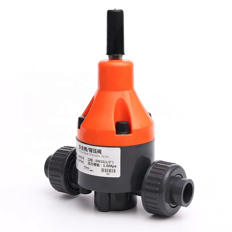
Expansion relief valves, also referred to as PRV’s, pressure relief valves, or safety valves, are designed to protect system tanks from overpressure, therefore a vital component. Overpressure can be caused by several things, including failure of an expansion vessel or a pressure-reducing valve.
Carrying on pressure tests on systems consists of adjusting the valve set pressure, performing a seat l,eakage test and a backpressure test. The set pressure test is always performed first.
Expansion relief valves are used in a range of industry demanding applications where pressure levels are critical for operation. Applications and industries include:
Air pressure relief valves, also known as PRVs or safety release valves, are installed to prevent pressure buildup. The valve opens slowly to release pressure when the level becomes too high.
If the pressure within an air compressor system gets too high, one of the components inside could explode. Essentially, pressure relief valves are designed to prevent uncontrolled depressurization events from occurring, protecting surrounding nearby equipment and employees during overpressure events.
Test the secondary pressure zone of all valves exceeding 1" inlet size with air or other suitable gas at a pressure of at least 30 psi. Use a suitable leak detection solution to verify tightness of all gasket joints and vent/drain plugs.
Expansion relief valves are often known as pressure relief valves and for a good reason. They come with a preset pressure built into their design to ensure once the valve recognizes the pressure limit, it opens to release the pressure-flow (fluid of compressed air) safely.
It’s advisable to permanently mount pressure relief valves in a vertical position so the spindle sits correctly and can operate effectively. Overtightening the valve can cause damage to the inlet and cause leakage too. For the inlet piping, keep it short and direct, it should have a shorter diameter than the valve, and it should always be far away from turbulence or vibration in the operating system.
A pressure relief valve can encounter overpressure or failure for many reasons, but the most common reasons are typically blocked discharge in the system, contaminants like dirt, rust, or sludge, or even valve misalignment can cause the pressure relief valve to fail. Maintenance and proper inspection periodically can help eliminate leakages, allowing a safe environment for operation and the operators.
As soon as mankind was able to boil water to create steam, the necessity of the safety device became evident. As long as 2000 years ago, the Chinese were using cauldrons with hinged lids to allow (relatively) safer production of steam. At the beginning of the 14th century, chemists used conical plugs and later, compressed springs to act as safety devices on pressurised vessels.
Early in the 19th century, boiler explosions on ships and locomotives frequently resulted from faulty safety devices, which led to the development of the first safety relief valves.
In 1848, Charles Retchie invented the accumulation chamber, which increases the compression surface within the safety valve allowing it to open rapidly within a narrow overpressure margin.
Today, most steam users are compelled by local health and safety regulations to ensure that their plant and processes incorporate safety devices and precautions, which ensure that dangerous conditions are prevented.
The principle type of device used to prevent overpressure in plant is the safety or safety relief valve. The safety valve operates by releasing a volume of fluid from within the plant when a predetermined maximum pressure is reached, thereby reducing the excess pressure in a safe manner. As the safety valve may be the only remaining device to prevent catastrophic failure under overpressure conditions, it is important that any such device is capable of operating at all times and under all possible conditions.
Safety valves should be installed wherever the maximum allowable working pressure (MAWP) of a system or pressure-containing vessel is likely to be exceeded. In steam systems, safety valves are typically used for boiler overpressure protection and other applications such as downstream of pressure reducing controls. Although their primary role is for safety, safety valves are also used in process operations to prevent product damage due to excess pressure. Pressure excess can be generated in a number of different situations, including:
The terms ‘safety valve’ and ‘safety relief valve’ are generic terms to describe many varieties of pressure relief devices that are designed to prevent excessive internal fluid pressure build-up. A wide range of different valves is available for many different applications and performance criteria.
In most national standards, specific definitions are given for the terms associated with safety and safety relief valves. There are several notable differences between the terminology used in the USA and Europe. One of the most important differences is that a valve referred to as a ‘safety valve’ in Europe is referred to as a ‘safety relief valve’ or ‘pressure relief valve’ in the USA. In addition, the term ‘safety valve’ in the USA generally refers specifically to the full-lift type of safety valve used in Europe.
Pressure relief valve- A spring-loaded pressure relief valve which is designed to open to relieve excess pressure and to reclose and prevent the further flow of fluid after normal conditions have been restored. It is characterised by a rapid-opening ‘pop’ action or by opening in a manner generally proportional to the increase in pressure over the opening pressure. It may be used for either compressible or incompressible fluids, depending on design, adjustment, or application.
Safety valves are primarily used with compressible gases and in particular for steam and air services. However, they can also be used for process type applications where they may be needed to protect the plant or to prevent spoilage of the product being processed.
Relief valve - A pressure relief device actuated by inlet static pressure having a gradual lift generally proportional to the increase in pressure over opening pressure.
Relief valves are commonly used in liquid systems, especially for lower capacities and thermal expansion duty. They can also be used on pumped systems as pressure overspill devices.
Safety relief valve - A pressure relief valve characterised by rapid opening or pop action, or by opening in proportion to the increase in pressure over the opening pressure, depending on the application, and which may be used either for liquid or compressible fluid.
In general, the safety relief valve will perform as a safety valve when used in a compressible gas system, but it will open in proportion to the overpressure when used in liquid systems, as would a relief valve.
Safety valve- A valve which automatically, without the assistance of any energy other than that of the fluid concerned, discharges a quantity of the fluid so as to prevent a predetermined safe pressure being exceeded, and which is designed to re-close and prevent further flow of fluid after normal pressure conditions of service have been restored.

The specification and purchase of valves in general can be a very complicated task depending on the time available that the instrumentation engineer has in a project and his own experience in developing this task. It starts with the fact that academic training, at least in Brazil, has very few courses aimed at industrial instrumentation and goes through the fact that each valve is, in essence, an engineering solution dedicated to an exclusive application. The probability of using a valve that has been specified and purchased incorrectly in another application is very low.
The need for use, selection, sizing, specification and, lastly, the purchase of valves usually arise within a multidisciplinary project; where several other very important instruments and equipments are allocating human resources that may even be working on parallel and independent projects and almost always with very lean HH. The result of this combination of factors is little time to sizing and specify a valve, be it for control or safety. This leads many engineers not to question why they adopt some requirements, especially when it is clear in the standard of the final customer that you have to follow it. When it comes to adopting API STD 526 in relation to the specification of safety valves, it is not very different.
Petrobras, which is one of the biggest motivating companies for the development of engineering in Brazil, has defined in its instrumentation standard N-1882D - Criteria for Elaboration of Instrumentation Projects; that safety valves must, among several requirements:Have the discharge orifices according to API STD 526;
API STD 526 requires the same above mentioned, so it´s clear that N-1882 was elaborated using as a basis, the API STD 526 guidelines and the adoption of this constructive standard proves to be practical since it meets at least four items of the N-1882D. This generated a culture within Brazilian engineering to adopt API STD 526 as a requirement in the design of the safety valve at least as a recommended practice.
API STD 526 is a standard with the objective of guiding engineers, manufacturers, end users and buyers in the selection, specification, manufacturing standardization and purchase of safety valves. These valves can be operated by spring with or without balancing bellows (conventional or self-operated); or operated by a pilot valve (pilot-operated).
All valves according to API STD 526 must have inlet and outlet flanged connections in accordance with ASME B16.5. The pressure and temperature limits are defined in tables 3 to 16 for spring-operated valves and in tables 17 to 30 for pilot-operated valves. It is worth noting that, even though the flanges are in accordance with ASME B16.5; we must not adopt the pressure x temperature limits of this standard, because these limits are higher than those defined by API STD 526.
It refers to the possibility of exchanging the safety valve of one manufacturer for another without compromising the protection of the equipment or requiring greater interference in the equipment or pipeline. This is possible for a few reasons.
The first one is the standardization of the discharge orifice areas, which defines maximum flow capacity values very close even for different manufacturers. The orifices are designated by letters that start in "D" and go up to "T". If one manufacturer “A” presents as a protection solution for an equipment, a safety valve 1D2 (one inch for inlet connection, orifice D and two inches for outlet connection) and manufacturer “B” presents another valve 1D2; we can say that “A” and “B” have interchangeable solutions.
Another reason that allows interchangeability is that API STD 526 also defines the distance from the face of the input flange to the center of the output flange; the distance between the face of the outlet flange and the center of the inlet flange and the connection patterns of the inlet and outlet flanges including the diameters and pressure classes themselves. In this way, it is possible to replace one valve with another with practically zero impacts on the piping and on existing equipment. Example: To replace a 1D2 valve from manufacturer A with a 1D2 valve from manufacturer B, there is no need to change flanges or pipe rearrangements.
Interchangeability also brings the benefit to the end user not being dependent on a single supplier that could, for different reasons, stop its commercial operations in a country, complicating or stopping the supply of valves or spare parts.
It is worth noting that, different manufacturers supplying interchangeable valves for the same application; may have different maximum certified discharge flow rates. The discharge orifice area calculations for API STD 526 valves are according to API STD 520 Part 1, but these are preliminary calculations that use recommended discharge coefficient (Kd) in the equations described in the items 5.6 to 5.10 of API STD 520 Part 1 as a starting point for making calculations possible. Each manufacturer has its certified discharge coefficient. Fortunately, most manufacturers have a certified discharge coefficient lower than that determined by the standard, which results in an area larger than the effective one defined by API STD 526. However, as not all manufacturers are; it is prudent then, when purchasing the valve, the instrumentation engineer requires the sizing report with the value of the maximum discharge flow certified from the manufacturer that is selling the solution.
API STD 526 defines the materials that must be used in the main parts of the safety valve such as body, bonnet, spring, flange and nozzle depending on the temperature and pressure that the valve is subjected at the opening moment.
Materials that are normally used in the manufacture of valves of all types such as carbon steel ASME SA-216 Gr. WCB and stainless steel ASME SA-351 Gr. CF8M are placed as minimum requirements for safety valves to be used in certain parts of the valve like body and the bonnet. This guarantees valves with similar performance, weight, mechanical strength and corrosion resistance from different manufacturers.
The requirements above does not restrain any supplier from adopte another material to produce his valve, that for many reasons, may be economically more attractive, since, it has higher pressure x temperature limits than those materials standardized by API STD 526. After all, the Instrumentation Engineer has to evaluate any material used regarding chemical compatibility with the process fluid.
API STD 526 also establishes that valves manufactured in accordance with this standard, must also comply with API STD 527. This last standard deals with the seat lekage while the valve is closed; or in other words; while the pressure scenario in the vessel or pipe is normal. All valves from all suppliers that will be involved in a purchasing process will have the same performance related to the seat leakage.
Although API STD 526 standardizes important parts of the valve, it does not defines all parts. It is still possible to find opportunities for innovation to deliver to the user, the best cost-benefit solution without neglecting the pressurized system protection that is so important.
The scope of the standard makes it clear that API STD 526 is a standard that should be used to purchase a safety and/or relief valve and defines minimum criteria to be met in order to be successful.
By standardizing all these criteria and requiring all suppliers of safety valves to produce a large amount of valves in accordance with API STD 526, a favorable scenario for bidding is created, cause the solutions become very similar. This way, the manufacturers will compete to get the lowest price.
It also facilitates the analysis of the engineer who always spends a good HH with the technical advice of the valve supply proposals. With a wide standardization, the time and cost necessary to evaluate, adjust and approve technical solutions is reduced. The standard itself presents in its appendix A, a data sheet containing the minimum information that must be specified in order to allow a technical and commercial consultation to manufacturers for the supply of spring and pilot operated safety valves. Annex B shows the minimum information that must appear on the nameplate.
Standardization allows the manufacture and strategic stock of nozzles, flanges, bonnets, bellows, caps and other components. In this way, it´s possible to assemble, test and ship the safety valve in the shortest possible time. It is not always necessary to cast parts or make more complicated adjustments that are not foreseen in the standard.
For small equipments such as pump sealing systems, pump recycles, air tanks for control valves, pig receivers and launchers, among others, that have a small volume of fluid to be relieved to normalize their pressure; using compact small valves is advantageous as they are easier to install. Usually threaded with ¾ ”NPT inlet and 1” NPT outlet, they are cheaper and have a discharge orifices with areas smallers than the D equivalent of API STD 526, which avoids making use of a oversized valve just to meet a construction standard. Oversized pressure safety valve can lead the valve to chattering, as the flow may be too small to be able to open the safety valve at once and the disc will again hit the inlet nozzle seat repeatedly, damaging the assembly and compromising the tightness or worse, compromising performance expected at the time of opening.
With simple design and with fewer parts, the safety valves for thermal relief (or compact), allows a good cost reduction. Since others legal requirements such as the National Board flow certificate and / or the ASME authorization certificate for the manufacturing site be part of the supply documentation; there is no greater cause for concern for the end user.
If the user still wants to replace an existing safety valve that does not comply with API STD 526, with another one according to API STD 526, he will have to evaluate whether the installation follows the recommendations of API RP 520 Pt 2. This evaluation that already has a cost, can lead to the conclusion that the pipes and connections need to be replaced and / or rearranged which would mean even more costs.
If costs is always an important factor in the projects; we can also verify that a valve according to API STD 526 does not always present the best cost benefit for the customer.
There are some good reasons for large companies to adopt API STD 526, if not as a requirement, at least as a recommended practice. All the criteria to be followed and the advantages presented, make API STD 526 kind of a guide to acquire a safety valve with the best cost benefit. It should not be forgotten, however, that the ultimate purpose of a safety valve is to open to guarantee the relief of a system that is in a pressurization scenario and to close when the situation is normalized. The construction according to API STD 526 does not replace the correct sizing and the need for ASME authorization certificates for the factory and the National Board certificate regarding the flow capacity of the tested model for the manufactured site.
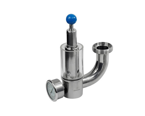
◎With sanitary design and completely material of stainless steel, the valves is the best choice for protection of equipments in diary, food, beverage, pharmaceutical and fine chemical industries.
◎When the pressure in the pipes is exceed the specific pressure, the valve will open automatically to make the liquid pass over,so that pressure in the pipeline is reduced.
◎The valve can be with handle in order to realize partial open. When the handle remains open on the operation spot, the detergent can flow though the flow valves.


 8613371530291