
asme safety valve code in stock

The Kingston Model 118CSS High Capacity Safety Valve is an ASME Code Certified, precision machined brass valve with a hard seat. This valve supports ASME Code applications up to 300 psi. It also features a stainless steel ball for durability and a pull ring for manual testing. Kingston Model 118CSS High Capacity Safety Valve is designed to flow extremely high volumes.Internal construction and performance are the same as Model 119CSS differing only by the pull ring used for manual testing.The Kingston Model 118CSS Safety Valve, like every Kingston Safety Valve, is set and tested at factory for quality and dependability.

Kingston Model 115 ASME Code Soft Seat Safety Valves are constructed of brass with a Viton seal and positive stop for a bubble-tight seal. This valve is equipped with a pull ring for manual testing. Internal construction and performance are the same as Model 114 differing only by the pull ring. The Kingston Model 115 ASME Code Soft Seat Safety Valve, like every Kingston Safety Valve, is set and tested at factory for quality and dependability. The Kingston Model 115 ASME Code Soft Seat Safety Valve is approved in Massachusetts and Washington DC and is stamped with UV & NB symbols. Registered in all Canadian provinces and territories.

Disclaimer: This Code of Ordinances and/or any other documents that appear on this site may not reflect the most current legislation adopted by the Municipality. American Legal Publishing Corporation provides these documents for informational purposes only. These documents should not be relied upon as the definitive authority for local legislation. Additionally, the formatting and pagination of the posted documents varies from the formatting and pagination of the official copy. The official printed copy of a Code of Ordinances should be consulted prior to any action being taken.
For further information regarding the official version of any of this Code of Ordinances or other documents posted on this site, please contact the Municipality directly or contact American Legal Publishing toll-free at 800-445-5588.

1/4" MNPT ASME safety valves are manufactured to ASME standards and certified by the national board of boiler and pressure vessel inspectors. Valves are interchangeable with all other ASME valves of same size and pressure. Valve resets after pressure drops by 50%. Valve has a pop off pressure of 125 PSI.

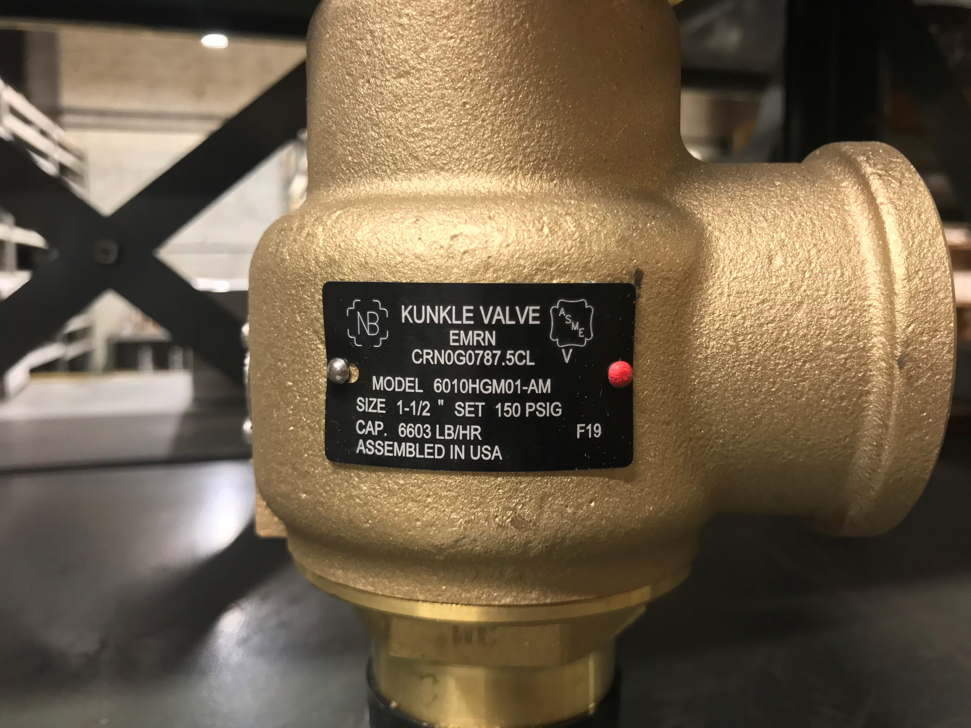
Cici Boiler Rooms is your one-stop-shop for safety valves! We stock a large inventory of common valves from Kunkle, Watts, and Conbraco. However, we can order any valve that you need.

In the United States, use of such devices was spurred by the 1,700 boiler explosions that resulted in 1,300 deaths from 1905 to 1911. By 1915, the American Society of Mechanical Engineers (ASME) published its first boiler code, Rules for Construction of Stationary Boilers and Allowable Working Pressures, incorporating rules for construction and installation of safety valves for boilers.
Since the introduction of that first ASME boiler code, many technological developments have occurred in the design and construction of pressure relief devices. Most jurisdictions in this country and Canada have adopted rules for pressure relief devices based on national codes and standards.
The ASME Boiler and Pressure Code exempted pressure relief devices that have set pressures less than 15 psi. These are known as non-ASME pressure relief devices, and they may be designed by using codes and standards other than ASME.
The performance of pressure relief devices is determined by ASME Pressure Test Code (PTC) 25-2014 Pressure Relief Devices. In addition, this code has standard definitions for the types and parts of pressure relief devices.
The American Petroleum Institute (API) has also published codes and standards for sizing, selection, installation and inspection of pressure relief devices. For example, API RP 520, Part I-2014 is widely used for sizing and selection of pressure relief devices in petroleum industries.
The primary purpose of a pressure relief valve is to open to relieve excess pressure, reclose and prevent further flow of fluid after normal conditions have been restored (Figure 5). A secondary purpose is to minimize damage to other system components through operation of the pressure relief valve itself. A pressure relief valve designed under ASME Boiler and Pressure Vessel Code is stamped with the certification mark, and one of the certification designators: V, NV, HV, UV, UV3 or TV.
The many types of pressure relief valves that exist are based on different designs and construction. Generally, they’re classified as: safety relief valves, relief valves and safety valves.
A conventional safety relief valve is a spring-loaded pressure relief valve characterized by a rapid-opening pop action. Conventional safety relief valves are used for applications where excessive variable or built-up back pressure is not present in the system. The operational characteristics of these valves are directly affected by changes in the back pressure on the valve.
The working principle of a conventional spring-loaded safety relief valve is based on the balance of force. The spring load is preset to equal the force the inlet fluid exerts on the closed disk when the system pressure is at the set pressure of the valve.
The disk remains seated on the nozzle in the closed position when the inlet pressure is below the set pressure. The valve opens when the inlet pressure exceeds set pressure, overcoming the spring force. The valve recloses when the inlet pressure is reduced to a level below the set pressure.
Once the valve has opened, an additional pressure buildup at C occurs. This additional force at C causes the disk to lift substantially at pop. The valve closes when the inlet pressure has dropped sufficiently below the set pressure. The pressure at which the valve resets is called the closing pressure. The difference between the set pressure and closing pressure is the blowdown.
In the design of a conventional valve, an important consideration is seat leakage. This leakage can result in continuous loss of system fluid and may cause progressive damage to the valve seating surface. Based on the seating material, conventional valves are classified as:
Metal-seated valves. Metal-to-metal seats are commonly made from stainless or other hard alloy steels and are normally used for high-temperature applications such as steam and corrosive media applications for processing a wide variety of chemicals.
Soft-seated valve. An alternative to metal is resilient disks that can be fixed to either or both the seating surfaces where tighter shut-off is required. They are common for gas or liquid applications. These inserts may be made from a number of different materials, but Vinton, nitrile or EPDM (ethylene propylene diene monomer) are the most common.
Balanced bellows with auxiliary balancing piston. With this valve, the balanced bellows seal the body and fluid stream from the bonnet and working parts. The auxiliary balancing piston assures proper valve performance by compensating for back pressure in case the bellows fail.
The primary difference between a pilot-operated safety relief valve and a spring-loaded pressure relief valve is that the pilot-operated valve uses process pressure to keep the valve closed instead of a spring. A pilot is used to sense process pressure and to pressurize or vent the dome pressure chamber, which controls the valve opening or closing.
A pilot-operated safety relief valve consists of the main valve, a floating, unbalanced piston assembly, and an external pilot. The pilot controls the pressure on the top side of the main valve’s unbalanced moving chamber. A resilient seat is normally attached to the lower end.
At below-set level, the pressure on opposite sides of the moving member is equal. When the set pressure is reached, the pilot opens and depressurizes the cavity on the top side so the unbalanced member moves upward, causing the main valve to relieve. When the process pressure decreases to a predetermined pressure, the pilot closes, the cavity above the piston is depressurized and the main valve closes.
The valves operate bubble tight at higher operating pressure-to-set pressure ratios, allowing operators to run very close to the vessel’s maximum allowable working pressure.
Valve movement to open or close is fully controlled by a source of power such as electricity, steam or water (hydraulic). The valve may discharge to the atmosphere or to a container that is at lower pressure. The discharge capacity can be affected by downstream conditions.
Power-actuated safety relief valves are used mostly for forced-flow steam generators with no fixed steam or waterline. They are also used in nuclear power plants.
A temperature and pressure-actuated safety relief valve (also called a T&P safety relief valve) is a pressure relief valve that may be actuated by temperature or pressure on the inlet side (Figure 10).
Such a valve is designed for dual purposes. First, the T&P valve prevents temperature within a vessel from rising above a specified limit (generally 210°F or 98°C). Second, the T&P valve prevents pressure in the vessel from rising above a specified value.
A relief valve is actuated by inlet static pressure and a gradual lift that is generally proportional to the increase in pressure over opening pressure. Such a valve can be provided with enclosed spring housing suitable for closed discharge system applications.
Relief valves are commonly used in liquid systems, especially for lower capacities and thermal expansion applications. They also can be used on pump systems.
Adjustable relief valves feature convenient adjustment of the pressure setting through the outlet port. They are suitable for non-vented or vented inline applications in chemical, petrochemical and high-purity gas industries.
Electronic relief valves (ERVs) are pilot-operated relief valves that offer zero leakage. The ERV package combines a zero-leakage isolation valve with electric controls to monitor and regulate system pressure. These valves provide protection either in a capacity-relieving function or simply in an overpressure-protection application.
Safety valves are typically used for boiler overpressure protection and other applications such as downstream from pressure-reducing controls. These valves are installed wherever the maximum allowable working pressure of boilers is likely to be exceeded. Safety valves are also used for compressible gases, in particular for steam and air.
Safety valves are classified according to the lift. The term “lift” refers to the amount of travel the valve undergoes as it moves from its closed position to the position required to produce the certified discharge capacity.
Low-lift are safety valves in which the valve lifts a distance of 1/24th of the bore diameter. Since the valve has a small lift, the capacity is much lower than other types.
High-lift are safety valves in which the valve lifts a distance of at least 1/12th of the bore diameter. High-lift valves are used on compressible fluids, where their action is more proportional.
Full-lift are safety valves for which the valve lifts a distance of at least 1/4th of the bore diameter. Full-lift valves are considered the best choice for general steam applications.
Test gags are used to hold the safety valve closed while equipment is subjected to a hydrostatic test. To avoid damage to the spindle and/or seat, care is required so the gag screw is not tightened.
Lifting mechanisms are used to open the pressure relief valves when the pressure under the valve disk is lower than the set pressure. These mechanisms are available in three basic types: plain lever, packaged lever and air-operated lifting devices.
Mohammad A. Malek, PhD, PE is pressure systems manager with Stanford University – SLAC. He is also an instructor with ASME. Dr. Malek is the author of the book Pressure Relief Devices published by McGraw-Hill. Reach him at malekm@asme.org.
A key advantage of selecting a butterfly valve is the reduction of space and weight to a system compared with other options such as ball, check, globe or gate valves.
Chatter is devastating to the internals of a Boiler Safety Valve. However, there is an even more important reason to avoid chatter at all cost. Chatter prevents the Safety Valve from reaching or sustaining full lift. This results in the Boiler is not being protected from a catastrophic overpressure event. Chatter may be the result of several issues. The least likely is an inaccurately adjusted Safety Valve. More than likely, chatter is an issue of piping or installation. Inlet or outlet piping may be the culprit. Reduced Piping, too much length or too many bends (or some combination of those three) on the Inlet or the Outlet may result in Chatter. On some occasions, the Safety Valve is improperly sized resulting in chatter due to insufficient flow through the Safety Valve when it is called on to operate. In other words, the Safety Valve is oversized and there is enough pressure to cause the Safety Valve to lift, but not enough flow to keep it open. Bigger is not always better. All the issues referred to above result in pressure drop at the PRV Inlet, which causes chatter.
The only mentions of pressure drop in ASME Sec I, Power Boiler Code, are in PG-68.1 for Superheater Safety Valve Set Pressure calculation and in PG-68.4 for Reheater Outlet Safety Valve Set Pressure calculation. PG-72.1 is a requirement designed to ensure the Safety Valve does not chatter. Notice PG-72 has a title that refers to “Operation of Pressure Relief Valves.” It is referring to the Blowdown Ring Settings, not the inlet Pressure Drop due to piping losses.
In a related code, ASME Sec VIII-1, UG-135, INSTALLATION, in UG-135(b)(1) states, “The opening through all pipe, fittings, and nonreclosing pressure relief devices (if installed) between a pressure vessel and its pressure relief valve shall have at least the area of the pressure relief valve inlet . The characteristics of this upstream system shall be such that the pressure drop will not reduce the relieving capacity below that required or adversely affect the proper operation of the pressure relief valve.”
ASME Sec VIII-1, Non-Mandatory Appendix M, M-6 (a) states, “M-6 INLET PRESSURE DROP FOR HIGH LIFT, TOP-GUIDED SAFETY, SAFETY RELIEF, AND PILOT-OPERATED PRESSURE RELIEF VALVES IN COMPRESSIBLE FLUID SERVICE (a) The nominal pipe size of all piping, valves and fittings, and vessel components between a pressure vessel and its safety, safety relief, or pilot-operated pressure relief valves shall be at least as large as the nominal size of the device inlet, and the flow characteristics of the upstream system shall be such that the cumulative total of all nonrecoverable inlet losses shall not exceed 3% of the valve set pressure. The inlet pressure losses will be based on the valve nameplate capacity corrected for the characteristics of the flowing fluid.
Following the requirements for Safety Valve installation in ASME Code, Sec I, Power Boilers, will resolve the chatter issue without calculating pressure losses in piping. Refer to ASME Sec I, PG-71, “Mounting of Pressure Relief Valves.” The restrictions on size and length of piping should be sufficient to prevent chatter due to piping losses.
Regarding the least likely cause of chatter, i.e. Safety Valve adjustment, if the Upper Adjusting Ring (Guide Ring) is too high, the Safety Valve will pop, but will not remain open. It will reclose and immediately pop again resulting in chatter. This is due to the Upper Ring providing an "outer wall" to the Huddling Chamber to keep the Steam underneath the Disc long enough to achieve full lift. Setting the Upper Ring too high removes the "outer wall" of the Huddling Chamber resulting in chatter. Setting the Safety Valve in accordance with PG-73.5.2 (a), which states, “Pressure relief valves for steam service shall be tested with steam. The blowdown control elements of the pressure relief valve shall be set to the manufacturer"s specifications,” should eliminate the possibility of chatter due to an adjusting ring setting. It should be noted that the typical, ASME Sec VIII, Pressure Relief Valve, is a single ring design, Safety-Relief Valve. The Adjusting Ring Setting of the Single Ring Design, Safety-Relief Valve will not result in Chatter.
(1) Boiler safety valves and safety relief valves must be as indicated in PG-67 through PG-73 of section I of the ASME Boiler and Pressure Vessel Code (incorporated by reference; see 46 CFR 52.01-1) except as noted otherwise in this section.
(3) On river steam vessels whose boilers are connected in batteries without means of isolating one boiler from another, each battery of boilers shall be treated as a single boiler and equipped with not less than two safety valves of equal size.
(4) (Modifies PG-70.) The total rated relieving capacity of drum and superheater safety valves as certified by the valve manufacturer shall not be less than the maximum generating capacity of the boiler which shall be determined and certified by the boiler manufacturer. This capacity shall be in compliance with PG-70 of section I of the ASME Boiler and Pressure Vessel Code.
(5) In the event the maximum steam generating capacity of the boiler is increased by any means, the relieving capacity of the safety valves shall be checked by an inspector, and, if determined to be necessary, valves of increased relieving capacity shall be installed.
(6) (Modifies PG-67.) Drum safety valves shall be set to relieve at a pressure not in excess of that allowed by the Certificate of Inspection. Where for any reason this is lower than the pressure for which the boiler was originally designed and the revised safety valve capacity cannot be recomputed and certified by the valve manufacturer, one of the tests described in PG-70(3) of section I of the ASME Boiler and Pressure Vessel Code shall be conducted in the presence of the Inspector to insure that the relieving capacity is sufficient at the lower pressure.
(8) Lever or weighted safety valves now installed may be continued in use and may be repaired, but when renewals are necessary, lever or weighted safety valves shall not be used. All such replacements shall conform to the requirements of this section.
(1) (Modifies PG-68.) Superheater safety valves shall be as indicated in PG-68 of section I of the ASME Boiler and Pressure Vessel Code except as noted otherwise in this paragraph.
(2) The setting of the superheater safety valve shall not exceed the design pressure of the superheater outlet flange or the main steam piping beyond the superheater. To prevent damage to the superheater, the drum safety valve shall be set at a pressure not less than that of the superheater safety valve setting plus 5 pounds minimum plus approximately the normal load pressure drop through the superheater and associated piping, including the controlled desuperheater if fitted. See also § 52.01-95(b) (1).
(3) Drum pilot actuated superheater safety valves are permitted provided the setting of the pilot valve and superheater safety valve is such that the superheater safety valve will open before the drum safety valve.
(1) (Modifies PG-71.) Safety valves shall be installed as indicated in PG-71 of section I of the ASME Boiler and Pressure Vessel Code except as noted otherwise in this paragraph.
(2) The final setting of boiler safety valves shall be checked and adjusted under steam pressure and, if possible, while the boiler is on the line and the steam is at operating temperatures, in the presence of and to the satisfaction of a marine inspector who, upon acceptance, shall seal the valves. This regulation applies to both drum and superheater safety valves of all boilers.
(3) The safety valve body drains required by PG-71 of section I of the ASME Boiler and Pressure Vessel Code shall be run as directly as possible from the body of each boiler safety valve, or the drain from each boiler safety valve may be led to an independent header common only to boiler safety valve drains. No valves of any type shall be installed in the leakoff from drains or drain headers and they shall be led to suitable locations to avoid hazard to personnel.
(1) (Modifies PG-72.) The operation of safety valves shall be as indicated in PG-72 of section I of the ASME Boiler and Pressure Vessel Code except as noted in paragraph (d)(2) of this section.
(2) (Modifies PG-73.) The lifting device required by PG-73.1.3 of section I of the ASME Boiler and Pressure Vessel Code shall be fitted with suitable relieving gear so arranged that the controls may be operated from the fireroom or engineroom floor.
Safety and Relief Valves are completely governed by codes and regulations. The two major codes are ASME (USA) and PED (Europe), and both are laws and failure to comply is a criminal offence. As you would imagine, they are both very similar but also do have some distinct differences. Because the codes are law, they must be adhered to when equipment is installed in a specific region. Most manufacturers therefore have both approvals. When installing a safety valve however, to be compliant with these codes you not only need to use an approved supplier, but you also need to select settings, and install them in accordance with the codes.
The governing standards and recommended practises are API 520 (USA) and EN4126 (Europe). API 520 incorporates more detail on correction factors (more conservative) for back pressure and viscosity, hence is the most widely used for valve sizing.
The European PED, from a legal perspective replaces the very many local codes in all European member states such as BS (UK), TUV (Germany), AFNOR NFE (France), Stoomwezen (The Netherlands), ISPESL (Italy).
Some European users may also stipulate their local code however in addition to the PED. Local codes have different ways of presenting things but often the results are the same.
ASME B16.34 - Applies to valves with flanged, threaded, and welding ends: This standard covers pressure/temperature ratings, dimensions, tolerances, materials, non-destructive examination requirements, testing and marking. This standard is not specifically applicable to Safety Relief Valves but is often used by manufacturers as good engineering practice.
ASME B16.5 - Applies to pipe flanges and flange fittings: Provides allowable materials, pressure / temperature limits and flange dimensions for standard ANSI flanges.
ASME itself does not certify the valves. This is done by a National Board (NB) and they certify the valves capacity and the valves complaince with the ASME code. It is then published in the "Red Book" - NB18, along with the true flow co-efficients as measured and approved by them. A copy can be found at www.nationalboard.org
As soon as mankind was able to boil water to create steam, the necessity of the safety device became evident. As long as 2000 years ago, the Chinese were using cauldrons with hinged lids to allow (relatively) safer production of steam. At the beginning of the 14th century, chemists used conical plugs and later, compressed springs to act as safety devices on pressurised vessels.
Early in the 19th century, boiler explosions on ships and locomotives frequently resulted from faulty safety devices, which led to the development of the first safety relief valves.
In 1848, Charles Retchie invented the accumulation chamber, which increases the compression surface within the safety valve allowing it to open rapidly within a narrow overpressure margin.
Today, most steam users are compelled by local health and safety regulations to ensure that their plant and processes incorporate safety devices and precautions, which ensure that dangerous conditions are prevented.
The principle type of device used to prevent overpressure in plant is the safety or safety relief valve. The safety valve operates by releasing a volume of fluid from within the plant when a predetermined maximum pressure is reached, thereby reducing the excess pressure in a safe manner. As the safety valve may be the only remaining device to prevent catastrophic failure under overpressure conditions, it is important that any such device is capable of operating at all times and under all possible conditions.
Safety valves should be installed wherever the maximum allowable working pressure (MAWP) of a system or pressure-containing vessel is likely to be exceeded. In steam systems, safety valves are typically used for boiler overpressure protection and other applications such as downstream of pressure reducing controls. Although their primary role is for safety, safety valves are also used in process operations to prevent product damage due to excess pressure. Pressure excess can be generated in a number of different situations, including:
The terms ‘safety valve’ and ‘safety relief valve’ are generic terms to describe many varieties of pressure relief devices that are designed to prevent excessive internal fluid pressure build-up. A wide range of different valves is available for many different applications and performance criteria.
In most national standards, specific definitions are given for the terms associated with safety and safety relief valves. There are several notable differences between the terminology used in the USA and Europe. One of the most important differences is that a valve referred to as a ‘safety valve’ in Europe is referred to as a ‘safety relief valve’ or ‘pressure relief valve’ in the USA. In addition, the term ‘safety valve’ in the USA generally refers specifically to the full-lift type of safety valve used in Europe.
Pressure relief valve- A spring-loaded pressure relief valve which is designed to open to relieve excess pressure and to reclose and prevent the further flow of fluid after normal conditions have been restored. It is characterised by a rapid-opening ‘pop’ action or by opening in a manner generally proportional to the increase in pressure over the opening pressure. It may be used for either compressible or incompressible fluids, depending on design, adjustment, or application.
Safety valves are primarily used with compressible gases and in particular for steam and air services. However, they can also be used for process type applications where they may be needed to protect the plant or to prevent spoilage of the product being processed.
Relief valve - A pressure relief device actuated by inlet static pressure having a gradual lift generally proportional to the increase in pressure over opening pressure.
Relief valves are commonly used in liquid systems, especially for lower capacities and thermal expansion duty. They can also be used on pumped systems as pressure overspill devices.
Safety relief valve - A pressure relief valve characterised by rapid opening or pop action, or by opening in proportion to the increase in pressure over the opening pressure, depending on the application, and which may be used either for liquid or compressible fluid.
In general, the safety relief valve will perform as a safety valve when used in a compressible gas system, but it will open in proportion to the overpressure when used in liquid systems, as would a relief valve.
Safety valve- A valve which automatically, without the assistance of any energy other than that of the fluid concerned, discharges a quantity of the fluid so as to prevent a predetermined safe pressure being exceeded, and which is designed to re-close and prevent further flow of fluid after normal pressure conditions of service have been restored.


 8613371530291