
hydraulic safety valve free sample

This direct-acting adjustable relief valve limits pressure at port 1 (on bottom of valve), by relieving to port 2 (on side of valve) when the relief pressure is reached. This valve is typically installed to limit pressure on the outlet of a pump or to limit pressure going to a hydraulic cylinder or motor. This relief pressure is preset at 1800 PSI when shipped. The valve has a minimum pressure of 400 PSI and a maximum pressure of 3000 PSI.

The purpose of the valve is to, when energized, provide a flow path for a flow of hydraulic fluid from its source to the hydraulic system. When de-energized, the valve blocks flow from the hydraulic energy source and vents the hydraulic system to tank.
Q: What is Control Reliablitiy?A: Control Reliability essentially states that the safety system be designed, constructed and installed such that the failure of a single component within the device or system should not prevent normal machine stopping action from taking place, but shall prevent a successive machine cycle from being initiated until the failure is corrected. To achieve “Control Reliability”, a device should feature both redundancy and fault detection.
A: A safety valve, as it pertains to fluid power, is a component that, when properly applied, can allow access to an otherwise hazardous area. This is achieved by isolating the hydraulic source away from the system and venting any residual system pressure, downstream from the valve, to tank.
A: During normal operation, the valve operates like a traditional 3-way. If either of the redundant elements malfunction, the safety PLC or safety relay, monitoring the state of the redundant switches, will command the valve to its safe condition.
A: The three different configurations of Control Reliable Safety Valves are 2-way for blocking applications, 3-way for block and bleed applications, and LOTO or Lockout/Tagout.
A: A relief valve is a device that limits the maximum pressure in a system. It does help to keep a system and its surrounding environment safe from catastrophic failures due to over-pressurization but it is not a true safety product. The safety valves that we refer to are redundantly monitored devices that meet the rigorous requirements of safety standards organizations such as ANSI and ISO.
A: A blocking valve, as it pertains to fluid power, is a component that, when properly applied, can allow access to an otherwise hazardous area. This is achieved by isolating the hydraulic source away from the system.
A: During normal operation, the valve operates like a traditional 2-way. If either of the redundant elements malfunction, the safety PLC or safety relay monitoring the state of the redundant switches will command the valve to its safe condition.
The primary purpose of a safety valve is to protect life, property and the environment. Safety valves are designed to open and release excess pressure from vessels or equipment and then close again.
The function of safety valves differs depending on the load or main type of the valve. The main types of safety valves are spring-loaded, weight-loaded and controlled safety valves.
Regardless of the type or load, safety valves are set to a specific set pressure at which the medium is discharged in a controlled manner, thus preventing overpressure of the equipment. In dependence of several parameters such as the contained medium, the set pressure is individual for each safety application.

Fulflo Specialties, Inc.’s hydraulic valves are relied on in oil and gas refining, pump and systems protection, industrial process, and military applications such as ships and aircraft carriers, as well as on compressor systems and lubrication skids. With reliable, chatter-free operation, Fulflo has become the relief valve of choice in a wide range of demanding environments.

In order to ensure that the maximum allowable accumulation pressure of any system or apparatus protected by a safety valve is never exceeded, careful consideration of the safety valve’s position in the system has to be made. As there is such a wide range of applications, there is no absolute rule as to where the valve should be positioned and therefore, every application needs to be treated separately.
A common steam application for a safety valve is to protect process equipment supplied from a pressure reducing station. Two possible arrangements are shown in Figure 9.3.3.
The safety valve can be fitted within the pressure reducing station itself, that is, before the downstream stop valve, as in Figure 9.3.3 (a), or further downstream, nearer the apparatus as in Figure 9.3.3 (b). Fitting the safety valve before the downstream stop valve has the following advantages:
• The safety valve can be tested in-line by shutting down the downstream stop valve without the chance of downstream apparatus being over pressurised, should the safety valve fail under test.
• When setting the PRV under no-load conditions, the operation of the safety valve can be observed, as this condition is most likely to cause ‘simmer’. If this should occur, the PRV pressure can be adjusted to below the safety valve reseat pressure.
Indeed, a separate safety valve may have to be fitted on the inlet to each downstream piece of apparatus, when the PRV supplies several such pieces of apparatus.
• If supplying one piece of apparatus, which has a MAWP pressure less than the PRV supply pressure, the apparatus must be fitted with a safety valve, preferably close-coupled to its steam inlet connection.
• If a PRV is supplying more than one apparatus and the MAWP of any item is less than the PRV supply pressure, either the PRV station must be fitted with a safety valve set at the lowest possible MAWP of the connected apparatus, or each item of affected apparatus must be fitted with a safety valve.
• The safety valve must be located so that the pressure cannot accumulate in the apparatus viaanother route, for example, from a separate steam line or a bypass line.
It could be argued that every installation deserves special consideration when it comes to safety, but the following applications and situations are a little unusual and worth considering:
• Fire - Any pressure vessel should be protected from overpressure in the event of fire. Although a safety valve mounted for operational protection may also offer protection under fire conditions,such cases require special consideration, which is beyond the scope of this text.
• Exothermic applications - These must be fitted with a safety valve close-coupled to the apparatus steam inlet or the body direct. No alternative applies.
• Safety valves used as warning devices - Sometimes, safety valves are fitted to systems as warning devices. They are not required to relieve fault loads but to warn of pressures increasing above normal working pressures for operational reasons only. In these instances, safety valves are set at the warning pressure and only need to be of minimum size. If there is any danger of systems fitted with such a safety valve exceeding their maximum allowable working pressure, they must be protected by additional safety valves in the usual way.
In order to illustrate the importance of the positioning of a safety valve, consider an automatic pump trap (see Block 14) used to remove condensate from a heating vessel. The automatic pump trap (APT), incorporates a mechanical type pump, which uses the motive force of steam to pump the condensate through the return system. The position of the safety valve will depend on the MAWP of the APT and its required motive inlet pressure.
This arrangement is suitable if the pump-trap motive pressure is less than 1.6 bar g (safety valve set pressure of 2 bar g less 0.3 bar blowdown and a 0.1 bar shut-off margin). Since the MAWP of both the APT and the vessel are greater than the safety valve set pressure, a single safety valve would provide suitable protection for the system.
Here, two separate PRV stations are used each with its own safety valve. If the APT internals failed and steam at 4 bar g passed through the APT and into the vessel, safety valve ‘A’ would relieve this pressure and protect the vessel. Safety valve ‘B’ would not lift as the pressure in the APT is still acceptable and below its set pressure.
It should be noted that safety valve ‘A’ is positioned on the downstream side of the temperature control valve; this is done for both safety and operational reasons:
Operation - There is less chance of safety valve ‘A’ simmering during operation in this position,as the pressure is typically lower after the control valve than before it.
Also, note that if the MAWP of the pump-trap were greater than the pressure upstream of PRV ‘A’, it would be permissible to omit safety valve ‘B’ from the system, but safety valve ‘A’ must be sized to take into account the total fault flow through PRV ‘B’ as well as through PRV ‘A’.
A pharmaceutical factory has twelve jacketed pans on the same production floor, all rated with the same MAWP. Where would the safety valve be positioned?
One solution would be to install a safety valve on the inlet to each pan (Figure 9.3.6). In this instance, each safety valve would have to be sized to pass the entire load, in case the PRV failed open whilst the other eleven pans were shut down.
If additional apparatus with a lower MAWP than the pans (for example, a shell and tube heat exchanger) were to be included in the system, it would be necessary to fit an additional safety valve. This safety valve would be set to an appropriate lower set pressure and sized to pass the fault flow through the temperature control valve (see Figure 9.3.8).
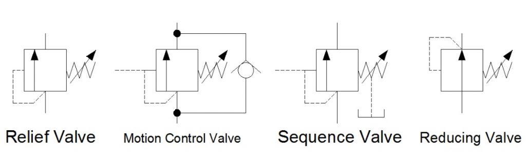
In Hydraulic Symbology 101 (read it here first), I covered the basic square used for pressure valves and also showed the most stripped-down versions of the two most commonly used pressure valve symbols, the relief valve and the pressure reducing valve. In this edition of Hydraulic Symbology, I’m going to cover the four primary pressure valves; the relief valve, motion control valve, sequence valve and reducing valve. Each is based on the same square symbol but are used quite differently in both circuits and real-life function.
Shown below are the quartet referenced from the same angle as each other. Each shows the basic square with a vertical arrow, abreast of a pilot line to the left and a spring to the right. The dashed line stands for a pilot signal, which is a fluid column of pressure energy used to push or act upon other components internal to the valve. The relief valve is normally closed (non-flowing). As pressure rises in the bottom port, energy pushes around to the pilot line to the left, but the valve is still closed. As the pressure continues to increase, the force pushing against the left side of the arrow starts to overcome the spring force applied from the right. When pilot pressure creates enough force, it can overcome spring pressure to slowly open the valve.
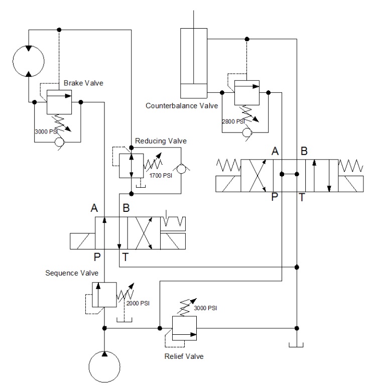
The below example shows a circuit with all four types of pressure valves used. It looks like a lot going on, but I’m going to break them all down one by one so they make sense. The relief valve teed into the right after the pump is drawn just as the relief valve above, and it operates under the same principle. The spring is pushing the valve closed with 3,000 psi of force, and in this circuit, it acts as the maximum limit pump pressure can achieve before being exhausted to tank.
Sequence valves are not much different from relief valves, and this is at once obvious by their similar appearance. This sequence valve downstream of the pump is exactly the same as the relief save for the drain line and reduced pressure setting. A sequence valve is purposed to provide a secondary flow path which occurs in sequence to a parallel function. In other words, when the cylinder in this application extends to the end of stroke, pressure will rise immediately. When pressure hits 2,000 psi, our sequence valve opens, diverting all pump flow to rotate the motor while the cylinder remains stalled and as long as its directional valve remains energized.
The sequence valve drain line is required to keep the valve’s performance consistent. Because the sequence valve experiences pressure on both ports, internal leakage allows pressure buildup inside the spring chamber which is additive to spring pressure. Without a drain, the pressure setting could rise or the valve could even lock up altogether. The key difference between a sequence valve and relief valve is the existence of this drain. A sequence valve makes an outstanding relief valve, in fact.
The pressure reducing valve is plumbed in just past the directional valve in the B-port. You’ll notice immediately how different this valve is than the others, and the extra astute will have noticed two differences, actually. The pilot line is drawn differently, this time showing its pressure signal originating downstream of the valve. This important contrast allows the valve to reduce downstream pressure to protect the actuator or sub-circuit beyond.
The reducing valve also differs in that it is normally flowing in its neutral state. Fluid is free to pass and allow the motor to spin, and not until downstream pressure from the motor rises to above the 1,700 psi setting of the valve does is start to close. The pilot line senses downstream pressure and starts to move the arrow to the right, choking flow to the motor. This reduced flow also reduces pressure, but it does so smoothly and with little drop in velocity. The effect is that downstream pressure is simply reduced.
You’ll notice in this example, there is also a check valve allowing flow to bypass the reducing valve altogether. This ensures the motor will experience little or no backpressure when it rotates in the opposite direction. Sometimes the reverse-flow check valve is not required, but it makes for good practice.
The last pressure valve to be discussed today is the motion control valve, which in my example is broken down into the brake valve and the counterbalance valve. The brake valve is used in motor applications as seen above. The valve is also very similar to the relief valve in design, and in fact, could still be used as one (as is the case for all pressure valve aside from the reducing valve). The reverse flow check valve allows free flow into the motor, allowing it to freely spin clockwise when the directional valve is left in its current detented position.
When the directional valve is reversed, however, the check valve blocks free flow and oil must now flow through the brake valve. This valve, you’ll notice, has two separate pilot lines merging at the same point on the valve. It has the same direct acting pilot line that rounds the corner, but there is an additional pilot source drawn from the opposite port of the motor. These dual pilot sources add interesting functionality to the brake valve in that it is both internally and externally piloted.
The internal, direct-acting signal will ensure the motor won’t move until a combination of load and pump pressure pushes through the motor to the tune of 3,000 psi. This allows the motor to stay “braked” while pump flow is non-existent. However, a direct-acting brake control valve is an inefficient method to control motion.
This valve has a trick up its sleeve — the surface area the external pilot works against is larger than the area of the direct acting side. The ratio of areas is often 4:1 but can be upwards of 8:1. The result is the pilot pressure needs to a quarter of work pressure, reducing energy lost to the brake valve. The brake valve is essentially braking to the tune of 3,000 psi, but opening to provide flow when the opposite port sees 375-750 psi. The valve uses pilot pressure as permission to open and allow flow, preventing unintended movement of the motor.
Lastly, we arrive at the motion control valve labelled counterbalance valve. It’s typically one and the same as a brake valve but used in cylinder applications. This example shows a relief valve set to 2,800 psi and is plumbed to the cap port of the cylinder. The reverse flow check valve ensures the cylinder will extend with little pressure drop, but when the directional valve is placed back in neutral, the counterbalance valve remains closed so the cylinder will not accidentally retract.
The counterbalance valve also has a pilot ratio enabling the valve to open once it senses pilot energy from the rod port, preventing accidental retraction. Counterbalance valves also work well on the rod port of a cylinder, which prevents overrunning loads as a cylinder moves “over center,” which is a condition of pulling forces on the rod.
Both examples of these motion control valves could have been employed with spring chamber drain ports, just as with the sequence valve. The drain keeps the spring chamber free from additional pressure, but in the case of this circuit, the open line to the reservoir through directional valves is enough to prevent excessive pressure. It’s when both ports of the pressure valve are continuously pressurized that a drain or vent is absolutely required.
There are many variations of pressure valves not covered here, but those will be discussed in a later episode. In Hydraulic Symbology 204, I’ll cover the essentials of flow control valves, including how they’re drawn and where they’re used.

Pressure valves use a poppet, ball or (rarely) a spool pushed offset by a spring, and that description you’ll find accurate for nearly every pressure valve ever made. This is because a pressure valve simply resists hydraulic pressure until the force to overcome its spring rises above the value of that spring — common sense. So if nearly every pressure valve operates using the same principle, why are there so many different types?
Indeed, a counterbalance valve works primarily the same as a relief valve, only with a few options to increase performance specifically to suit its function. The type of pressure valve you need comes down to the location and purpose within your hydraulic system. The four basic versions of the pressure valve are the relief valve, motion control valve, sequence valve and reducing valve (see Figure 1).
The relief valve represents the most straightforward option and is the foundation of the other three. It may be as elementary as a hardened chrome ball pushed against a conical seat by a spring offering no adjustment. Such a rudimental fixed relief valve doesn’t often appear in hydraulics, but such a design could be made adjustable by adding a sealed screw assembly to adjust the spring pre-load.
Any spring in a pressure valve has a stiffness designed to resist compression, and how much that stiffness increases as the spring compresses is called spring rate. The higher the pressure range of the valve, the higher the rate of its spring. Spring rate is often expressed as “pounds per inch,” meaning x pounds of force will compress the spring by one inch.
No pressure valve has an infinite range of adjustability since any spring experiences a usable range. We find that weak springs cannot operate in the upper reaches of high pressure, and stiff springs do not allow for low-pressure operation. A valve manufacturer understands the limitations of the spring, so they offer various spring rates for their valves to suit customers’ needs. For example, 0-25 bar, 0-75 bar and 35-250 bar spring range offerings for any given valve may be available from the manufacturer.
Common construction stylesEven for the same application, pressure valves also differ in their construction. Three common construction styles are thedirect-acting, pilot operated and balanced piston. The direct-acting relief valve employs a ball or poppet held closed by a spring, and hydraulic pressure acts directly on the ball or poppet to compress the spring and relieve fluid to limit upstream pressure.
The direct-acting valve is simple and effective but has its limitations. Pressure override defines the difference between when a pressure valve “cracks” open and when it is fully open. The cracking pressure of direct-acting relief valves occurs well below the actual pressure setting, itself defined as system pressure with the valve fully open. As a result, some valves experience pressure override as poorly as half of their maximum set pressure, while others may experience only 10-20% of that maximum set pressure.
Pressure override may even be defined as a (direct operated) pressure valve’s efficiency, especially as described as a relief valve. Although cracking pressure may result in only 5% loss of pump flow, the loss rate is linear from cracking pressure right up until set pressure. As you approach the set value of the relief valve, more flow is directed to the tank instead of creating useful work. Not only does that relief flow reduce actuator velocity, but it also creates pure heat as a result.
A simple pilot-operated relief valve resembles two relief valves in series. A smaller relief acts as a pilot to the mainstage valve and controls the opening force of that mainstage. Because the pilot relief contains the high-pressure spring, the mainstage valve may use a weaker spring since pilot pressure offers the remaining resistance to early cracking pressure. A pilot-operated relief valve exhibits lower pressure override than direct-acting valves and is also available in very high flow options.
When very low-pressure override is required, look for the balanced piston relief valve, which itself is a pilot-operated configuration. Its mainstage poppet has the same surface area on the pressure and spring side, and system pressure is balanced on either side. Only the force value of the spring holds the poppet shut, requiring very soft springs due to their balanced nature. The spring value and pressure override are one and the same, so if you set the valve to 3,000 psi and the spring offers 50 psi worth of force, the cracking pressure occurs at 2,950 psi.
Selection based on design requirementsNow that we have the basics down on the construction and operation of pressure valves, we can discuss which pressure valve you need in each part of your circuit. Figure 2 shows a fictional circuit displaying myriad pressure valves in various locations. I’ll go through each to describe what valve best suits the design requirement.
You need to limit system pressure —This job is best suited for a relief valve, which really exists primarily as a backup to prevent excessive pressure from causing damage. A relief valve should be avoided if you’re looking for a solution to “hold” pressure, which only causes heat as a consequence.
Select your relief valve to suit your maximum pressure rating and so that the valve may be set above maximum working pressure. For example, if your actuators require 2,000 psi, setting your relief valve to 2,000 psi will result in flow going to tank rather than to your actuators. And as previously discussed, be sure to select a valve with appropriate pressure override. Ensure any closed-center hydraulic system only uses balanced piston relief valves to prevent the pump from unloading and set the pressure around 200 psi above the compensator setting to prevent the valve from fighting with the pressure compensator.
You need to operate functions in sequence — A clever trick to automate hydraulic functions comes from using what is essentially a relief valve inline where it directs its path towards a secondary circuit or actuator. When used as such, the relief valve changes its name to a sequence valve. Perhaps more than any other pressure valve, the sequence valve most closely resembles the relief valve except that it requires an external drain or vent to its spring chamber.
Unlike a relief valve with a direct path to tank, the sequence valve experiences pressure on both ports. With nowhere for leakage flow to exit, it can build up in the spring chamber where trapped pressure is additive to spring pressure. The drain prevents such possibility to lock up should pressure leak into the spring chamber for too long.
You can see in Figure 2 how once the cylinder lifts and then bottoms out, the 2,000 psi setting of the sequence valve is the path of least resistance compared to the 3,000 psi of the relief valve. Next, the sequence valve opens, directing fluid to the motor function.
You need to limit pressure in a subcircuit —Not every actuator wants or needs full system pressure, and even sometimes, you wish to limit force at an actuator accurately. Therefore, your pressure valve of choice for subcircuit pressure control is the reducing valve. Unique amongst pressure valves, this is the only version normally open, meaning it flows in its neutral position.
The pressure reducing valve takes its pilot signal from downstream toward the actuator, and when pressure rises above its setting, it closes the flow path so that downstream pressure decays enough to result in reduced pressure. In some ways, it’s a hybrid valve that controls flow to control pressure. Like their sequence valve counterparts, many reducing valves require a drain port since pressure acts upon both work ports. The drain also allows the valve to maintain its reduced pressure should downstream pressure rise due to load or thermal induced reasons.
In the sample circuit, you’ll also notice a check valve. This is because the check valve allows free reverse flow so the valve only reduces pressure downstream and reduces valves flow poorly in reverse (and sometimes not at all).
You’re free to use as many reducing valves as there are subcircuits or work ports. So yes, you can use a reducing valve to limit pressure in each work port and at different settings as well.
You need to control an over-center or overrunning load —Sometimes gravity likes to pull or push a load farther than you wish to move it, such as the boom on a crane or a winch lowering a lift. You wish to lower the loads safely, and at a specific rate, a relief valve may be added to essentially meter out to control the descent. Although a relief will indeed work, you may risk pressure intensification as the load pulls the same time you’re pushing.
Motion control valves (counterbalance valves for cylinders and brake valves for motors) have some features that allow the safe, steady control over loads. Using a pilot signal from the opposing work port, the motion control valve remains closed until it receives the pilot signal when it opens to allow the load to move. Then, the valve modulates itself seamlessly to balance the pressure directly applied from the load with the pilot signal telling the valve to open.
Reverse flow check valves allow pump flow easy access in the opposite direction, which is common to every motion control valve. Drains or vents are available with motion control valves since the potential to simultaneously expose all ports to pressure exists. However, most often, the outlet port of the valve does have a free path to tank when the valve is in action, so a drain is not always necessary.

There are two main types of selector valves: open-center and closed-center. An open center valve allows a continuous flow of system hydraulic fluid through the valve even when the selector is not in a position to actuate a unit. A closed-center selector valve blocks the flow of fluid through the valve when it is in the NEUTRAL or OFF position. [Figure 1-A]
Selector valves may be poppet-type, spool-type, piston-type, rotary-type, or plug-type. [Figure 2] Regardless, each selector valve has a unique number of ports. The number of ports is determined by the particular requirements of the system in which the valve is used. Closed-centered selector valves with four ports are most common in aircraft hydraulic systems. These are known as four-way valves. Figure 1 illustrates how this valve connects to the pressure and return lines of the hydraulic system, as well as to the two ports on a common actuator. Most selector valves are mechanically controlled by a lever or electrically controlled by solenoid or servo. [Figure 3]
The four ports on a four-way selector valve always have the same function. One port receives pressurized fluid from the system hydraulic pump. A second port always returns fluid to the reservoir. The third and forth ports are used to connect the selector valve to the actuating unit. There are two ports on the actuating unit. When the selector valve is positioned to connect pressure to one port on the actuator, the other actuator port is simultaneously connected to the reservoir return line through selector valve. [Figure 1-B] Thus, the unit operates in a certain direction. When the selector valve is positioned to connect pressure to the other port on the actuating unit, the original port is simultaneously connected to the return line through the selector valve and the unit operates in the opposite direction. [Figure 1-C]
Figure 4 illustrates the internal flow paths of a solenoid operated selector valve. The closed center valve is shown in the NEUTRAL or OFF position. Neither solenoid is energized. The pressure port routes fluid to the center lobe on the spool, which blocks the flow. Fluid pressure flows through the pilot valves and applies equal pressure on both ends of the spool. The actuator lines are connected around the spool to the return line.
When selected via a switch in the cockpit, the right solenoid is energized. The right pilot valve plug shifts left, which blocks pressurized fluid from reaching the right end of the main spool. The spool slides to the right due to greater pressure applied on the left end of the spool. The center lobe of the spool no longer blocks system pressurized fluid, which flows to the actuator through the left actuator line. At the same time, return flow is blocked from the main spool left chamber so the actuator (not shown) moves in the selected direction. Return fluid from the moving actuator flows through the right actuator line past the spool and into the return line. [Figure 5]
Typically, the actuator or moving device contacts a limit switch when the desired motion is complete. The switch causes the right solenoid to de-energize and the right pilot valve reopens. Pressurized fluid can once again flow through the pilot valve and into the main spool right end chamber. There, the spring and fluid pressure shift the spool back to the left into the NEUTRAL or OFF position shown in Figure 4.
To make the actuator move in the opposite direction, the cockpit switch is moved in the opposite direction. All motion inside the selector valve is the same as described above but in the opposite direction. The left solenoid is energized. Pressure is applied to the actuator through the right port and return fluid from the left actuator line is connected to the return port through the motion of the spool to the left.
Check ValveAnother common flow control valve in aircraft hydraulic systems is the check valve. A check valve allows fluid to flow unimpeded in one direction, but prevents or restricts fluid flow in the opposite direction. A check valve may be an independent component situated in-line somewhere in the hydraulic system or it may be built-in to a component. When part of a component, the check valve is said to be an integral check valve.
A typical check valve consists of a spring loaded ball and seat inside a housing. The spring compresses to allow fluid flow in the designed direction. When flow stops, the spring pushes the ball against the seat which prevents fluid from flowing in the opposite direction through the valve. An arrow on the outside of the housing indicated the direction in which fluid flow is permitted. [Figure 6] A check valve may also be constructed with spring loaded flapper or coned shape piston instead of a ball.
Orifice-Type Check ValveSome check valves allow full fluid flow in one direction and restricted flow in the opposite direction. These are known as orifice-type check valves, or damping valves. The valve contains the same spring, ball, and seat combination as a normal check valve but the seat area has a calibrated orifice machined into it. Thus fluid flow is unrestricted in the designed direction while the ball is pushed off of its seat. The downstream actuator operates at full speed. When fluid back flows into the valve, the spring forces the ball against the seat which limits fluid flow to the amount that can pass through the orifice. The reduced flow in this opposite direction slows the motion, or dampens, the actuator associated with the check valve. [Figure 6]
An orifice check valve may be included in a hydraulic landing gear actuator system. When the gear is raised, the check valve allows full fluid flow to lift the heavy gear at maximum speed. When lowering the gear, the orifice in the check valve prevents the gear from violently dropping by restricting fluid flow out of the actuating cylinder.
Sequence ValvesSequence valves control the sequence of operation between two branches in a circuit; they enable one unit to automatically set another unit into motion. An example of the use of a sequence valve is in an aircraft landing gear actuating system. In a landing gear actuating system, the landing gear doors must open before the landing gear starts to extend. Conversely, the landing gear must be completely retracted before the doors close. A sequence valve installed in each landing gear actuating line performs this function. A sequence valve is somewhat similar to a relief valve except that, after the set pressure has been reached, the sequence valve diverts the fluid to a second actuator or motor to do work in another part of the system. There are various types of sequence valves. Some are controlled by pressure, some are controlled mechanically, and some are controlled by electric switches.
Pressure-Controlled Sequence ValveThe operation of a typical pressure-controlled sequence valve is illustrated in Figure 4. The opening pressure is obtained by adjusting the tension of the spring that normally holds the piston in the closed position. (Note that the top part of the piston has a larger diameter than the lower part.) Fluid enters the valve through the inlet port, flows around the lower part of the piston and exits the outlet port, where it flows to the primary (first) unit to be operated. [Figure 7-A] This fluid pressure also acts against the lower surface of the piston.
When the primary actuating unit completes its operation, pressure in the line to the actuating unit increases sufficiently to overcome the force of the spring, and the piston rises. The valve is then in the open position. [Figure 7-B] The fluid entering the valve takes the path of least resistance and flows to the secondary unit. A drain passage is provided to allow any fluid leaking past the piston to flow from the top of the valve. In hydraulic systems, this drain line is usually connected to the main return line.
Mechanically Operated Sequence ValveThe mechanically operated sequence valve is operated by a plunger that extends through the body of the valve. [Figure 8] The valve is mounted so that the plunger is operated by the primary unit. A check valve, either a ball or a poppet, is installed between the fluid ports in the body. It can be unseated by either the plunger or fluid pressure. Port A and the actuator of the primary unit are connected by a common line. Port B is connected by a line to the actuator of the secondary unit. When fluid under pressure flows to the primary unit, it also flows into the sequence valve through port A to the seated check valve in the sequence valve. In order to operate the secondary unit, the fluid must flow through the sequence valve. The valve is located so that the primary unit moves the plunger as it completes its operation. The plunger unseats the check valve and allows the fluid to flow through the valve, out port B, and to the secondary unit.
Priority ValvesA priority valve gives priority to the critical hydraulic subsystems over noncritical systems when system pressure is low. For instance, if the pressure of the priority valve is set for 2,200 psi, all systems receive pressure when the pressure is above 2,200 psi. If the pressure drops below 2,200 psi, the priority valve closes and no fluid pressure flows to the noncritical systems. [Figure 9] Some hydraulic designs use pressure switches and electrical shutoff valves to assure that the critical systems have priority over noncritical systems when system pressure is low.
Quick Disconnect ValvesQuick disconnect valves are installed in hydraulic lines to prevent loss of fluid when units are removed. Such valves are installed in the pressure and suction lines of the system immediately upstream and downstream of the power pump. In addition to pump removal, a power pump can be disconnected from the system and a hydraulic test stand connected in its place. These valve units consist of two interconnecting sections coupled together by a nut when installed in the system. Each valve section has a piston and poppet assembly. These are spring loaded to the closed position when the unit is disconnected. [Figure 10]
Hydraulic FusesA hydraulic fuse is a safety device. Fuses may be installed at strategic locations throughout a hydraulic system. They detect a sudden increase in flow, such as a burst downstream, and shut off the fluid flow. By closing, a fuse preserves hydraulic fluid for the rest of the system. Hydraulic fuses are fitted to the brake system, leading edge flap and slat extend and retract lines, nose landing gear up and down lines, and the thrust reverser pressure and return lines. One type of fuse, referred to as the automatic resetting type, is designed to allow a certain volume of fluid per minute to pass through it. If the volume passing through the fuse becomes excessive, the fuse closes and shuts off the flow. When the pressure is removed from the pressure supply side of the fuse, it automatically resets itself to the open position. Fuses are usually cylindrical in shape, with an inlet and outlet port at opposite ends. [Figure 11]
Pressure Control ValvesThe safe and efficient operation of fluid power systems, system components, and related equipment requires a means of controlling pressure. There are many types of automatic pressure control valves. Some of them are an escape for pressure that exceeds a set pressure; some only reduce the pressure to a lower pressure system or subsystem; and some keep the pressure in a system within a required range.
Relief ValvesHydraulic pressure must be regulated in order to use it to perform the desired tasks. A pressure relief valve is used to limit the amount of pressure being exerted on a confined liquid. This is necessary to prevent failure of components or rupture of hydraulic lines under excessive pressures. The pressure relief valve is, in effect, a system safety valve.
The design of pressure relief valves incorporates adjustable spring-loaded valves. They are installed in such a manner as to discharge fluid from the pressure line into a reservoir return line when the pressure exceeds the predetermined maximum for which the valve is adjusted. Various makes and designs of pressure relief valves are in use, but, in general, they all employ a spring-loaded valving device operated by hydraulic pressure and spring tension. [Figure 12] Pressure relief valves are adjusted by increasing or decreasing the tension on the spring to determine the pressure required to open the valve. They may be classified by type of construction or uses in the system. The most common types of valve are:
Ball type-in pressure relief valves with a ball-type valving device, the ball rests on a contoured seat. Pressure acting on the bottom of the ball pushes it off its seat, allowing the fluid to bypass.
Sleeve type-in pressure relief valves with a sleeve-type valving device, the ball remains stationary and a sleeve-type seat is moved up by the fluid pressure. This allows the fluid to bypass between the ball and the sliding sleeve-type seat.
Poppet type-in pressure relief valves with a poppet-type valving device, a cone-shaped poppet may have any of several design configurations; however, it is basically a cone and seat machined at matched angles to prevent leakage. As the pressure rises to its predetermined setting, the poppet is lifted off its seat, as in the ball-type device. This allows the fluid to pass through the opening created and out the return port.
Pressure relief valves cannot be used as pressure regulators in large hydraulic systems that depend on engine-driven pumps for the primary source of pressure because the pump is constantly under load and the energy expended in holding the pressure relief valve off its seat is changed into heat. This heat is transferred to the fluid and, in turn, to the packing rings, causing them to deteriorate rapidly. Pressure relief valves, however, may be used as pressure regulators in small, low-pressure systems or when the pump is electrically driven and is used intermittently.
System relief valve—the most common use of the pressure relief valve is as a safety device against the possible failure of a pump compensator or other pressure regulating device. All hydraulic systems that have hydraulic pumps incorporate pressure relief valves as safety devices.
Thermal relief valve—the pressure relief valve is used to relieve excessive pressures that may exist due to thermal expansion of the fluid. They are used where a check valve or selector valve prevents pressure from being relieved through the main system relief valve. Thermal relief valves are usually smaller than system relief valves. As pressurized fluid in the line in which it is installed builds to an excessive amount, the valve poppet is forced off its seat. This allows excessive pressurized fluid to flow through the relief valve to the reservoir return line. When system pressure decreases to a predetermined pressure, spring tension overcomes system pressure and forces the valve poppet to the closed position.
Pressure RegulatorsThe term pressure regulator is applied to a device used in hydraulic systems that are pressurized by constant-delivery type pumps. One purpose of the pressure regulator is to manage the output of the pump to maintain system operating pressure within a predetermined range. The other purpose is to permit the pump to turn without resistance (termed unloading the pump) at times when pressure in the system is within normal operating range. The pressure regulator is located in the system so that pump output can get into the system pressure circuit only by passing through the regulator. The combination of a constant-delivery-type pump and the pressure regulator is virtually the equivalent of a compensator-controlled, variable-delivery-type pump. [Figure 13]
Figure 13. The location of a pressure regulator in a basic hydraulic system. The regulator unloads the constant delivery pump by bypassing fluid to the return line when the predetermined system pressure is reached
Pressure ReducersPressure reducing valves are used in hydraulic systems where it is necessary to lower the normal system operating pressure by a specified amount. Pressure reducing valves provide a steady pressure into a system that operates at a lower pressure than the supply system. A reducing valve can normally be set for any desired downstream pressure within the design limits of the valve. Once the valve is set, the reduced pressure is maintained regardless of changes in supply pressure (as long as the supply pressure is at least as high as the reduced pressure desired) and regardless of the system load, if the load does not exceed the designed capacity of the reducer. [Figure 14]
Shuttle ValvesIn certain fluid power systems, the supply of fluid to a subsystem must be from more than one source to meet system requirements. In some systems, an emergency system is provided as a source of pressure in the event of normal system failure. The emergency system usually actuates only essential components. The main purpose of the shuttle valve is to isolate the normal system from an alternate or emergency system. It is small and simple; yet, it is a very important component. [Figure 15] The housing contains three ports—normal system inlet, alternate or emergency system inlet, and outlet. A shuttle valve used to operate more than one actuating unit may contain additional unit outlet ports.
Enclosed in the housing is a sliding part called the shuttle. Its purpose is to seal off one of the inlet ports. There is a shuttle seat at each inlet port. When a shuttle valve is in the normal operation position, fluid has a free flow from the normal system inlet port, through the valve, and out through the outlet port to the actuating unit. The shuttle is seated against the alternate system inlet port and held there by normal system pressure and by the shuttle valve spring. The shuttle remains in this position until the alternate system is activated. This action directs fluid under pressure from the alternate system to the shuttle valve and forces the shuttle from the alternate system inlet port to the normal system inlet port. Fluid from the alternate system then has a free flow to the outlet port, but is prevented from entering the normal system by the shuttle, which seals off the normal system port.
Shutoff ValvesShutoff valves are used to shutoff the flow of fluid to a particular system or component. In general, these types of valves are electrically powered. Shutoff valves are also used to create a priority in a hydraulic system and are controlled by pressure switches. [Figure 15]


 8613371530291