
the safety valve reduces pressure at in stock
As well, the compressor in the system is capable of pumping air pressure to 500 psi (3450kPa), which poses danger to both the driver and others around the vehicle.
The driver of a commercial vehicle must know that the safety valve makes the sound of a machine gun when it releases excess air pressure from the system.

One-Way Check Valve: This device allows air to flow in one direction only. All air tanks on air-braked vehicles must have a check valve located between the air compressor and the first reservoir. The check valve keeps air from going out if the air compressor develops a leak. [California Commercial Driver Handbook]

As soon as mankind was able to boil water to create steam, the necessity of the safety device became evident. As long as 2000 years ago, the Chinese were using cauldrons with hinged lids to allow (relatively) safer production of steam. At the beginning of the 14th century, chemists used conical plugs and later, compressed springs to act as safety devices on pressurised vessels.
Early in the 19th century, boiler explosions on ships and locomotives frequently resulted from faulty safety devices, which led to the development of the first safety relief valves.
In 1848, Charles Retchie invented the accumulation chamber, which increases the compression surface within the safety valve allowing it to open rapidly within a narrow overpressure margin.
Today, most steam users are compelled by local health and safety regulations to ensure that their plant and processes incorporate safety devices and precautions, which ensure that dangerous conditions are prevented.
The principle type of device used to prevent overpressure in plant is the safety or safety relief valve. The safety valve operates by releasing a volume of fluid from within the plant when a predetermined maximum pressure is reached, thereby reducing the excess pressure in a safe manner. As the safety valve may be the only remaining device to prevent catastrophic failure under overpressure conditions, it is important that any such device is capable of operating at all times and under all possible conditions.
Safety valves should be installed wherever the maximum allowable working pressure (MAWP) of a system or pressure-containing vessel is likely to be exceeded. In steam systems, safety valves are typically used for boiler overpressure protection and other applications such as downstream of pressure reducing controls. Although their primary role is for safety, safety valves are also used in process operations to prevent product damage due to excess pressure. Pressure excess can be generated in a number of different situations, including:
The terms ‘safety valve’ and ‘safety relief valve’ are generic terms to describe many varieties of pressure relief devices that are designed to prevent excessive internal fluid pressure build-up. A wide range of different valves is available for many different applications and performance criteria.
In most national standards, specific definitions are given for the terms associated with safety and safety relief valves. There are several notable differences between the terminology used in the USA and Europe. One of the most important differences is that a valve referred to as a ‘safety valve’ in Europe is referred to as a ‘safety relief valve’ or ‘pressure relief valve’ in the USA. In addition, the term ‘safety valve’ in the USA generally refers specifically to the full-lift type of safety valve used in Europe.
Pressure relief valve- A spring-loaded pressure relief valve which is designed to open to relieve excess pressure and to reclose and prevent the further flow of fluid after normal conditions have been restored. It is characterised by a rapid-opening ‘pop’ action or by opening in a manner generally proportional to the increase in pressure over the opening pressure. It may be used for either compressible or incompressible fluids, depending on design, adjustment, or application.
Safety valves are primarily used with compressible gases and in particular for steam and air services. However, they can also be used for process type applications where they may be needed to protect the plant or to prevent spoilage of the product being processed.
Relief valve - A pressure relief device actuated by inlet static pressure having a gradual lift generally proportional to the increase in pressure over opening pressure.
Relief valves are commonly used in liquid systems, especially for lower capacities and thermal expansion duty. They can also be used on pumped systems as pressure overspill devices.
Safety relief valve - A pressure relief valve characterised by rapid opening or pop action, or by opening in proportion to the increase in pressure over the opening pressure, depending on the application, and which may be used either for liquid or compressible fluid.
In general, the safety relief valve will perform as a safety valve when used in a compressible gas system, but it will open in proportion to the overpressure when used in liquid systems, as would a relief valve.
Safety valve- A valve which automatically, without the assistance of any energy other than that of the fluid concerned, discharges a quantity of the fluid so as to prevent a predetermined safe pressure being exceeded, and which is designed to re-close and prevent further flow of fluid after normal pressure conditions of service have been restored.

This section tells you about air brakes. If you want to drive a truck, bus, or pull a trailer with air brakes, you need to read this section. If you want to pull a trailer with air brakes, you also need to read Section 6: Combination Vehicles in this handbook.
Air brakes use compressed air to make the brakes work. Air brakes are a good and safe way of stopping large and heavy vehicles, but the brakes must be well maintained and used properly.
CDL Air Brake Requirements. For CDL purposes, a vehicle’s air brake system must meet the above definition and contain the following, which will be checked during the vehicle inspection test:
If the vehicle you use for your road test does not have these components, your vehicle will not be considered as having an air brake system and you will have a “No Air Brakes” (“L”) restriction on your CDL.
A full service brake application must deliver to all brake chambers not less than 90 percent of the air reservoir pressure remaining with the brakes applied (CVC §26502).
The air compressor pumps air into the air storage tanks (reservoirs). The air compressor is connected to the engine through gears or a v-belt. The compressor may be air cooled or cooled by the engine cooling system. It may have its own oil supply or be lubricated by engine oil. If the compressor has its own oil supply, check the oil level before driving.
The governor controls when the air compressor will pump air into the air storage tanks. When air tank pressure rises to the “cut-out” level (around 125 pounds per-square-inch or “psi”), the governor stops the compressor from pumping air. When the tank pressure falls to the “cut-in” pressure (around 100 psi), the governor allows the compressor to start pumping again.
Air storage tanks are used to hold compressed air. The number and size of air tanks varies among vehicles. The tanks will hold enough air to allow the brakes to be used several times, even if the compressor stops working.
Compressed air usually has some water and some compressor oil in it, which is bad for the air brake system. The water can freeze in cold weather and cause brake failure. The water and oil tend to collect in the bottom of the air tank. Be sure that you drain the air tanks completely. Each air tank is equipped with a drain valve in the bottom. There are 2 types:
Some air brake systems have an alcohol evaporator to put alcohol into the air system. This helps to reduce the risk of ice in air brake valves and other parts during cold weather. Ice inside the system can make the brakes stop working.
Check the alcohol container and fill up as necessary. (every day during cold weather). Daily air tank drainage is still needed to get rid of water and oil (unless the system has automatic drain valves).
A safety relief valve is installed in the first tank the air compressor pumps air to. The safety valve protects the tank and the rest of the system from too much pressure. The valve is usually set to open at 150 psi. If the safety valve releases air, something is wrong. Have the fault fixed by a mechanic.
You engage the brakes by pushing down the brake pedal (It is also called a foot valve or treadle valve). Pushing the pedal down harder applies more air pressure. Letting up on the brake pedal reduces the air pressure and releases the brakes. Releasing the brakes lets some compressed air go out of the system, so the air pressure in the tanks is reduced. It must be made up by the air compressor. Pressing and releasing the pedal unnecessarily can let air out faster than the compressor can replace it. If the pressure gets too low, the brakes will not work.
Brake Drums, Shoes, and Linings. Brake drums are located on each end of the vehicle’s axles. The wheels are bolted to the drums. The braking mechanism is inside the drum. To stop, the brake shoes and linings are pushed against the inside of the drum. This causes friction, which slows the vehicle (and creates heat). The heat a drum can take without damage depends on how hard and how long the brakes are used. Too much heat can make the brakes stop working.
S-cam Brakes. When you push the brake pedal, air is let into each brake chamber. Air pressure pushes the rod out, moving the slack adjuster, thus twisting the brake camshaft. This turns the S-cam (it is shaped like the letter “S”). The S-cam forces the brake shoes away from one another and presses them against the inside of the brake drum. When you release the brake pedal, the S-cam rotates back and a spring pulls the brake shoes away from the drum, letting the wheels roll freely again. See Figure 5.2.
One feature is a completely internal adjustment system which is designed to continually keep the brake in proper adjustment. S-cam brakes, on the other hand, require an external slack adjuster. The second feature is a unique cam design that applies the brake shoe. Unlike a standard drum brake that has either a single or double anchor-pin brake, the CamLaster slides the shoes down an inclined ramp on a cam to evenly contact the brake drum.
Wedge Brakes. In this type of brake, the brake chamber push rod pushes a wedge directly between the ends of 2 brake shoes. This shoves them apart and against the inside of the brake drum. Wedge brakes may have a single brake chamber or 2 brake chambers that push wedges in at both ends of the brake shoes. Wedge type brakes may be self-adjusting or may require manual adjustment.
Disc Brakes.In air-operated disc brakes, air pressure acts on a brake chamber and slack adjuster, like S-cam brakes. But instead of the S-cam, a “power screw” is used. The pressure of the brake chamber on the slack adjuster turns the power screw. The power screw clamps the disc or rotor between the brake lining pads of a caliper, similar to a large c-clamp.
All vehicles with air brakes have a pressure gauge connected to the air tank. If the vehicle has a dual air brake system, there will be a gauge for each half of the system (or a single gauge with two needles). Dual systems will be discussed later. These gauges tell you how much pressure is in the air tanks.
This gauge shows how much air pressure you are applying to the brakes. (This gauge is not on all vehicles.) Increasing application pressure to hold the same speed means the brakes are fading. You should slow down and use a lower gear. Brakes that are of adjustment, air leaks, or mechanical problems can also cause the need for increased pressure.
A low air pressure warning signal is required on vehicles with air brakes. A warning signal you can see must come on when the air pressure in the tanks falls between 55 and 75 psi (or 1/2 the compressor governor cutout pressure on older vehicles). The warning is usually a red light. A buzzer may also come on.
Another type of warning is the “wig wag.” This device drops a mechanical arm into your view when the pressure in the system drops between 55 and 75 psi. An automatic wig wag will rise out of your view when the pressure in the system goes above 55 and 75 psi. The manual reset type must be placed in the “out of view” position manually. It will not stay in place until the pressure in the system is above 55 psi.
Drivers behind you must be warned when you put your brakes on. The air brake system does this with an electric switch that works by air pressure. The switch turns on the brake lights when you put on the air brakes.
Some vehicles made before 1975 have a front brake limiting valve and a control in the cab. The control is usually marked “normal” and “slippery.” When you put the control in the “slippery” position, the limiting valve cuts the “normal” air pressure to the front brakes by half. Limiting valves were used to reduce the chance of the front wheels skidding on slippery surfaces. However, they actually reduce the stopping power of the vehicle. Front wheel braking is good under all conditions. Tests have shown front wheel skids from braking are not likely even on ice. Make sure the control is in the “normal” position to have normal stopping power.
Many vehicles have automatic front wheel limiting valves. They reduce the air to the front brakes except when the brakes are put on very hard (60 psi or more application pressure). The driver cannot control these valves.
All trucks, truck tractors, and buses must be equipped with emergency brakes and parking brakes. They must be held on by mechanical force (because air pressure can eventually leak away). Spring brakes are usually used to meet these needs. Powerful springs are held back by air pressure when driving. If the air pressure is removed, the springs put on the brakes. A parking brake control in the cab allows the driver to let the air out of the spring brakes. This lets the springs put the brakes on. A leak in the air brake system, which causes all the air to be lost, will also cause the springs to put on the brakes.
Tractor and straight truck spring brakes will come fully on when air pressure drops to a range of 20 to 45 psi (typically 20 to 30 psi). Do not wait for the brakes to come on automatically. When the low air pressure warning light, and buzzer first come on, bring the vehicle to a safe stop right away, while you can still control the brakes.
The braking power of spring brakes depends on the brakes being in adjustment. If the brakes are not adjusted properly, neither the regular brakes nor the emergency/parking brakes will work right.
In newer vehicles with air brakes, you put on the parking brakes using a diamond-shaped, yellow, push-pull control knob. You pull the knob out to put the parking brakes (spring brakes) on, and push it in to release them. On older vehicles, the parking brakes may be controlled by a lever. Use the parking brakes whenever you park.
Caution.Never push the brake pedal down when the spring brakes are on. If you do, the brakes could be damaged by the combined forces of the springs and the air pressure. Many brake systems are designed so this will not happen. Not all systems are set up that way, and those that are may not always work. It is much better to develop the habit of not pushing the brake pedal down when the spring brakes are on.
Modulating Control Valves. In some vehicles a control handle on the dash board may be used to apply the spring brakes gradually. This is called a modulating valve. It is spring-loaded so you have a feel for the braking action. The more you move the control lever, the harder the spring brakes come on. They work this way so you can control the spring brakes if the service brakes fail. When parking a vehicle with a modulating control valve, move the lever as far as it will go and hold it in place with the locking device.
Dual Parking Control Valves. When main air pressure is lost, the spring brakes come on. Some vehicles, such as buses, have a separate air tank which can be used to release the spring brakes. This is so you can move the vehicle in an emergency. One of the valves is a push-pull type and is used to put on the spring brakes for parking. The other valve is spring loaded in the “out” position. When you push the control in, air from the separate air tank releases the spring brakes so you can move. When you release the button, the spring brakes come on again. There is only enough air in the separate tank to do this a few times. Therefore, plan carefully when moving. Otherwise, you may be stopped in a dangerous location when the separate air supply runs out. See Figure 5.3.
Truck tractors with air brakes built on or after March 1, 1997, and other air brakes vehicles (trucks, buses, trailers, and converter dollies) built on or after March 1, 1998, are required to be equipped with anti-lock brakes. Many commercial vehicles built before these dates have been voluntarily equipped with ABS. Check the certification label for the date of manufacture to determine if your vehicle is equipped with ABS. ABS is a computerized system that keeps your wheels from locking up during hard brake applications.
Trailers will have yellow ABS malfunction lamps on the left side, either on the front or rear corner. Dollies manufactured on or after March 1, 1998, are required to have a lamp on the left side.
On newer vehicles, the malfunction lamp comes on at start-up for a bulb check, and then goes out quickly. On older systems, the lamp could stay on until you are driving over 5 mph.
In the case of towed units manufactured before it was required by the DOT, it may be difficult to tell if the unit is equipped with ABS. Look under the vehicle for the ECU and wheel speed sensor wires coming from the back of the brakes.
ABS is an addition to your normal brakes. It does not decrease or increase your normal braking capability. ABS only activates when wheels are about to lock up.
Most heavy-duty vehicles use dual air brake systems for safety. A dual air brake system has 2 separate air brake systems, which use a single set of brake controls. Each system has its own air tanks, hoses, lines, etc. One system typically operates the regular brakes on the rear axle or axles. The other system operates the regular brakes on the front axle (and possibly one rear axle). Both systems supply air to the trailer (if there is one). The first system is called the “primary” system. The other is called the “secondary” system. See Figure 5.4.
Before driving a vehicle with a dual air system, allow time for the air compressor to build up a minimum of 100 psi pressure in both the primary and secondary systems. Watch the primary and secondary air pressure gauges (or needles, if the system has 2 needles in one gauge). Pay attention to the low air pressure warning light and buzzer. The warning light and buzzer should shut off when air pressure in both systems rises to a value set by the manufacturer. This value must be greater than 55 psi.
The warning light and buzzer should come on before the air pressure drops below 55 psi in either system. If this happens while driving, you should stop right away and safely park the vehicle. If one air system is very low on pressure, either the front or the rear brakes will not be operating fully. This means it will take you longer to stop. Bring the vehicle to a safe stop, and have the air brakes system fixed.
This device allows air to flow in one direction only. All air tanks on air-brake vehicles must have a check valve located between the air compressor and the first reservoir (CVC §26507). The check valve keeps air from going out if the air compressor develops a leak.
You should use the basic 7-step inspection procedure described in Section 2 to inspect your vehicle. There is more to inspect on a vehicle with air brakes than one without them. These components are discussed below, in the order that they fit into the 7-step method.
Check the air compressor drive belt (if the compressor is belt-driven). If the air compressor is belt-driven, check the condition and tightness of the belt. It should be in good condition.
Check slack adjusters on S-cam brakes. Park on level ground and chock the wheels to prevent the vehicle from moving. Release the parking brakes so you can move the slack adjusters. Use gloves and pull hard on each slack adjuster that you can reach. If a slack adjuster moves more than about one inch where the push rod attaches to it, it probably needs adjustment. Adjust it or have it adjusted. Vehicles with too much brake slack can be very hard to stop. Out-of-adjustment brakes are the most common problem found in roadside inspections. Be safe. Check the slack adjusters.
All vehicles built since 1994 have automatic slack adjusters. Even though automatic slack adjusters adjust themselves during full brake applications, they must be checked.
Automatic adjusters should not have to be manually adjusted except when performing maintenance on the brakes and during installation of the slack adjusters. In a vehicle equipped with automatic adjusters, when the pushrod stroke exceeds the legal brake adjustment limit, it is an indication that a mechanical problem exists in the adjuster itself, a problem exists with the related foundation brake components, or the adjuster was improperly installed.
The manual adjustment of an automatic adjuster to bring a brake pushrod stroke within legal limits is generally masking a mechanical problem and is not fixing it. Further, routine adjustment of most automatic adjusters will likely result in premature wear of the adjuster itself. It is recommended that when brakes equipped with automatic adjusters are found to be out of adjustment, the driver takes the vehicle to a repair facility as soon as possible to have the problem corrected. The manual adjustment of automatic slack adjusters is dangerous because it may give the driver a false sense of security regarding the effectiveness of the braking system.
The manual adjustment of an automatic adjuster should only be used as a temporary measure to correct the adjustment in an emergency situation. It is likely the brake will soon be back out of adjustment since this procedure usually does not fix the underlying adjustment problem.
Automatic slack adjusters are made by different manufacturers and do not all operate the same. Therefore, the specific manufacturer’s service manual should be consulted prior to troubleshooting a brake adjustment problem.
Brake drums (or discs) must not have cracks longer than 1/2 the width of the friction area. Linings (friction material) must not be loose or soaked with oil or grease and must not be worn dangerously thin (less than 1/4 inch). Mechanical parts must be in place, not broken, or missing. Check the air hoses connected to the brake chambers to make sure they are not cut or worn due to rubbing.
All air brake system tests in this section are considered important and each can be considered critical parts of the in-cab air brakes tests. The items marked with an asterisk (*) in this section are required for testing purposes during the vehicle inspection portion of the CDL skills test. They may be performed in any order as long as they are performed correctly and effectively. If these items are not demonstrated and the parameters for each test are not verbalized correctly, it is considered an automatic failure of the vehicle inspection portion of the skills test.
To perform this test, the driver must start with the engine running and with the air pressure built to governor cut-out (120–140 psi or another level specified by the manufacturer). The driver identifies when cut-out occurred, shuts off the engine, chocks the wheels if necessary, releases the parking brake (all vehicles) and tractor protection valve (combination vehicle), and fully applies the foot brake. The driver then holds the foot brake for 1 minute after stabilization of the air gauge. The driver checks the air gauge to see that the air pressure drops no more than 3 pounds in one minute (single vehicle) or 4 pounds in 1 minute (combination vehicle) and listens for air leaks. The driver must identify how much air the system lost and verbalize the maximum air loss rate allowed for the representative vehicle being tested.
For a Class A combination vehicle, if the power unit is equipped with air brakes and the trailer is equipped with electric/surge brakes, the pressure drop should be no more than 3 psi.
An air loss greater than those listed above, indicates a problem in the braking system and repairs are needed before operating the vehicle. If the air loss is too much, check for air leaks and fix any that are identified.
For testing purposes, you must be able to demonstrate this test and verbalize the allowable air loss for your vehicle. For testing purposes, identify if the air loss rate is too much.
To perform this test the vehicle must have enough air pressure so the low-pressure warning signal is off. The engine maybe on or off; however, the key must be in the “on” or “battery charge” position. Next, the driver begins fanning off the air pressure by rapidly applying and releasing the foot brake. Low-air warning devices (buzzer, light, and flag) must activate before air pressure drops below 55 psi or the level specified by the manufacturer. The driver must indicate the approximate pressure when the device gave warning and identify the parameter at which this must occur; no lower than 55 psi. See Figure 5.5.
For testing purposes, identify and verbalize the pressure at which the low air pressure warning signal activates and identify the parameter(s) at which this should occur. On large buses, it is common for low-pressure warning devices to signal at 80–85 psi. If testing in a large bus, identify the parameter(s) mentioned above (55–75 psi) and inform the examiner that your vehicle’s low-pressure warning devices are designed to activate at a higher pressure.
If the warning signal does not work, you could lose air pressure and not know it. This could cause sudden emergency braking in a single-circuit air system. In dual systems, the stopping distance will be increased. Only limited braking can be done before the spring brakes come on.
To perform this test, the parking brake (all vehicles) and tractor protection valve (combination vehicles) must be released; (engine running or not) as the driver fans off the air pressure. Normally between 20-45 psi (or the level specified by the manufacturer) on a tractor-trailer combination vehicle, the tractor protection valve and parking brake valve should close (pop out). On other combination vehicle types and single vehicle types, the parking brake valve should close (pop out). The driver must identify and verbalize the approximate pressure at which the brake(s) activated.
The parking brake valve will not pop out on buses that are equipped with an emergency park brake air reservoir (tank). If your bus is equipped with an emergency park brake air tank, you must perform the spring brake test for triple reservoir vehicles to check the automatic actuation of the spring brakes.
If the parking brake valve does not pop out when the air pressure has been reduced to approximately 20 psi, you must demonstrate that the spring brakes have activated. To do this, you must:
The spring brakes should drag and prevent the vehicle from easily moving forward. If the spring brakes do not prevent the vehicle from easily moving forward, your road test will be postponed.
This test must only be performed on single vehicles designed with an isolated parking brake reservoir. Do not perform this test on combination vehicles.
To perform this test, the engine must be running at normal operating idle, typically 600–900 rpms. Observe the air gauge to determine if the pressure builds at the proper rate. For dual air systems, the pressure should build from approximately 85 to 100 psi within 45 seconds. For single air systems (in pre-1975 vehicles), the pressure should build from approximately 50 to 90 psi within 3 minutes.
With a basically fully-charged air system (within the effective operating range for the compressor), turn off the engine, release all brakes, and let the system settle (air gauge needle stops moving). Time for 1 minute. The air pressure should not drop more than:
Wait for normal air pressure, release the parking brake, move the vehicle forward slowly (about 5 mph), and apply the brakes firmly using the brake pedal. Note any vehicle “pulling” to one side, unusual feel, or delayed stopping action.
Push the brake pedal down. Control the pressure so the vehicle comes to a smooth, safe stop. If you have a manual transmission, do not push the clutch in until the engine rpm is down close to idle. When stopped, select a starting gear.
When you brake hard on slippery surfaces in a vehicle without ABS, your wheels may lock up. When your steering wheels lock up, you lose steering control. When your other wheels lock up, you may skid, jackknife, or even spin the vehicle.
ABS helps you avoid wheel lock up. The computer senses impending lockup, reduces the braking pressure to a safe level, and helps you maintain control.
Having ABS on only the tractor, only the trailer, or even on only 1 axle, still gives you more control over the vehicle during braking. Brake normally.
When only the tractor has ABS, you should be able to maintain steering control, and there is less chance of jackknifing. But keep your eye on the trailer and let up on the brakes (if you can safely do so) if it begins to swing out.
When only the trailer has ABS, the trailer is less likely to swing out. But if you lose steering control or start a tractor jackknife, let up on the brakes (if you can safely do so) until you gain control.
— There is only 1 exception to this procedure. If you always drive a straight truck or combination with working ABS on all axles, in an emergency stop, you can fully apply the brakes.
If somebody suddenly pulls out in front of you, your natural response is to hit the brakes. This is a good response if there is enough distance to stop, and you use the brakes correctly.
You should brake in a way that will keep your vehicle in a straight line and allow you to turn if it becomes necessary. You can use the “controlled braking” or “stab braking” method.
Controlled Braking. With this method, you apply the brakes as hard as you can without locking the wheels. Keep steering wheel movements very small while doing this. If you need to make a larger steering adjustment or if the wheels lock, release the brakes. Reapply the brakes as soon as you can.
Stab Braking. Apply your brakes all the way. Release the brakes when wheels lock up. As soon as the wheels start rolling, apply the brakes fully again. (It can take up to one second for the wheels to start rolling after you release the brakes. If you reapply the brakes before the wheels start rolling, the vehicle will not straighten out.)
Stopping distance was described in Section 2.6 under “Speed and Stopping Distance.” With air brakes there is an added delay, “brake lag”. This is the time required for the brakes to work after the brake pedal is pushed. With hydraulic brakes (used on cars and light/medium trucks), the brakes work instantly. However, with air brakes, it takes a little time (one half second or more) for the air to flow through the lines to the brakes. Thus, the total stopping distance for vehicles with air brake systems is made up of 4 different factors.
The air brake lag distance at 55 mph on dry pavement adds about 32 feet. Therefore, at 55 mph for an average driver under good traction and brake conditions, the total stopping distance is over 450 feet. See Figure 5.6.
Brakes are designed so that brake shoes or pads rub against the brake drum or discs to slow the vehicle. Braking creates heat, but brakes are designed to take a lot of heat. However, brakes can fade or fail from excessive heat caused by using them too much and not relying on the engine braking effect.
Excessive use of the service brakes results in overheating and leads to brake fade. Brake fade results from excessive heat causing chemical changes in the brake lining, which reduce friction, and cause expansion of the brake drums. As the overheated drums expand, the brake shoes and linings have to move farther to contact the drums, and the force of this contact is reduced. Continued overuse may increase brake fade until the vehicle cannot be slowed down or stopped.
Brake fade is also affected by adjustment. To safely control a vehicle, every brake must do its share of the work. Brakes out of adjustment will stop doing their share before those that are in adjustment. The other brakes can then overheat and fade, and there will not be enough braking available to control the vehicle(s). Brakes can get out of adjustment quickly, especially when they are hot. Therefore, check brake adjustment often.
Remember, the use of brakes on a long and/or steep downgrade is only a supplement to the braking effect of the engine. Once the vehicle is in the correct low gear, the following is the proper braking technique:
When your speed has been reduced to approximately 5 mph below your “safe” speed, release the brakes. (This application should last for about 3 seconds.)
If your “safe” speed is 40 mph, you would not apply the brakes until your speed reaches 40 mph. You now apply the brakes hard enough to gradually reduce your speed to 35 mph and then release the brakes. Repeat this as often as necessary until you have reached the end of the downgrade.
If the low air pressure warning comes on, stop and safely park your vehicle as soon as possible. There might be an air leak in the system. Controlled braking is possible only while enough air remains in the air tanks. The spring brakes will come on when the air pressure drops into the range of 20 to 45 psi. A heavily loaded vehicle will take a long distance to stop because the spring brakes do not work on all axles. Lightly loaded vehicles or vehicles on slippery roads may skid out of control when the spring brakes come on. It is much safer to stop while there is enough air in the tanks to use the foot brakes.
Any time you park, use the parking brakes, except as noted below. Pull the parking brake control knob out to apply the parking brakes and push it in to release. The control will be a yellow, diamond-shaped knob labeled “parking brakes” on newer vehicles. On older vehicles, it may be a round blue knob or some other shape (including a lever that swings from side to side or up and down).
Do not use the parking brakes if the brakes are very hot (from just having come down a steep grade), or if the brakes are very wet in freezing temperatures. If they are used while they are very hot, they can be damaged by the heat. If they are used in freezing temperatures when the brakes are very wet, they can freeze so the vehicle cannot move. Use wheel chocks on a level surface to hold the vehicle. Let hot brakes cool before using the parking brakes. If the brakes are wet, use the brakes lightly while driving in a low gear to heat and dry them.
If your vehicle does not have automatic air tank drains, drain your air tanks at the end of each working day to remove moisture and oil. Otherwise, the brakes could fail.
Never leave your vehicle unattended without applying the parking brakes or chocking the wheels. Your vehicle might roll away and cause injury and damage.
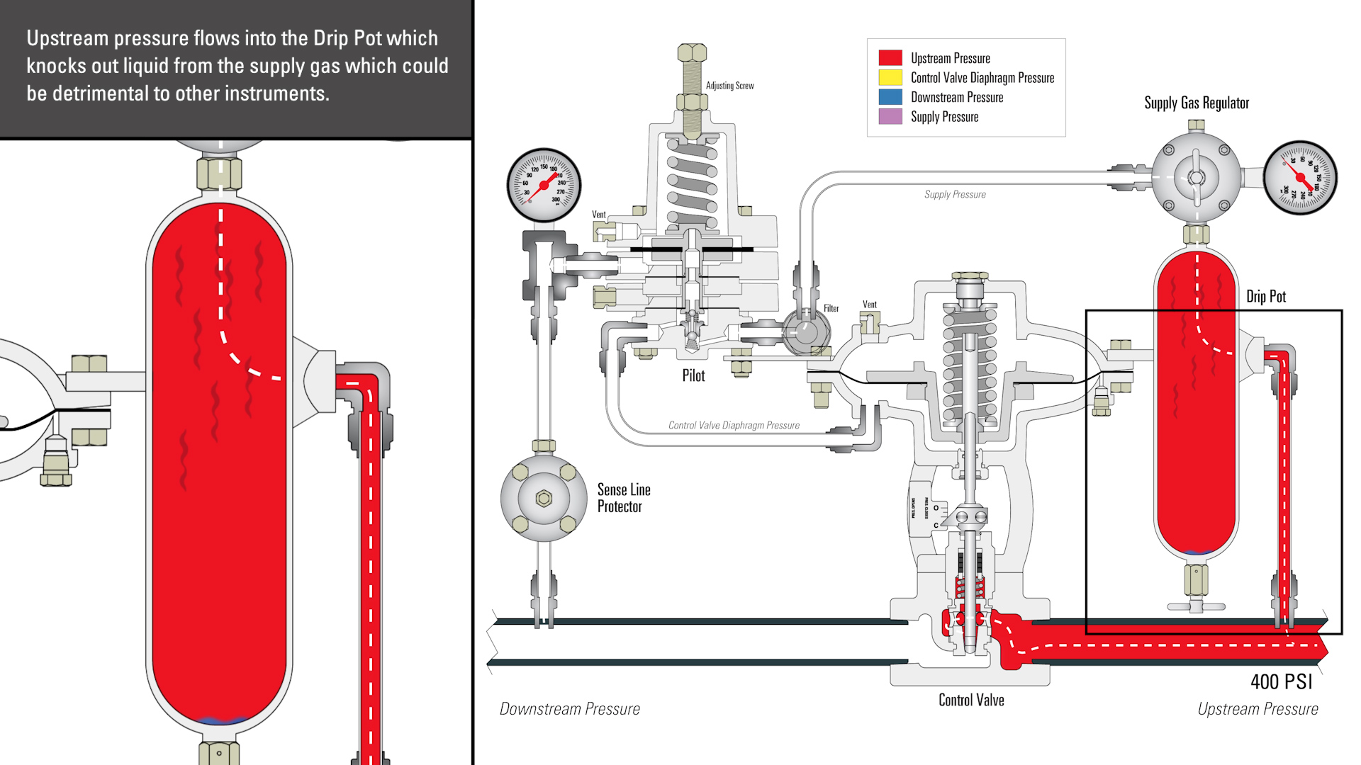
:max_bytes(150000):strip_icc()/Water-pressure-regulator-2718696_color-8cb88034226e4c43aae61588c648e23f.jpg)
The supply reservoir is protected from being over-pressurized and bursting by a safety valve (Fig.17). This valve is pre-set (usually at 150 psi [1,034 kPa]) and will blow off excess pressure. Once pressure is lowered, the safety valve will re-seal until an over-pressurized condition exists again. If a safety valve blows off excess pressure, this indicates a problem with the governor. The problem should be dealt with immediately by a qualified person.

Finding a quality driving school in can be a difficult and time consuming task. driving-schools.com comprehensive database of driving schools helps you pick one that’s right for you.

Curtiss-Wright"s selection of Pressure Relief Valves comes from its outstanding product brands Farris and Target Rock. We endeavor to support the whole life cycle of a facility and continuously provide custom products and technologies. Boasting a reputation for producing high quality, durable products, our collection of Pressure Relief Valves is guaranteed to provide effective and reliable pressure relief.
While some basic components and activations in relieving pressure may differ between the specific types of relief valves, each aims to be 100% effective in keeping your equipment running safely. Our current range includes numerous valve types, from flanged to spring-loaded, threaded to wireless, pilot operated, and much more.
A pressure relief valve is a type of safety valve designed to control the pressure in a vessel. It protects the system and keeps the people operating the device safely in an overpressure event or equipment failure.
A pressure relief valve is designed to withstand a maximum allowable working pressure (MAWP). Once an overpressure event occurs in the system, the pressure relief valve detects pressure beyond its design"s specified capability. The pressure relief valve would then discharge the pressurized fluid or gas to flow from an auxiliary passage out of the system.
Below is an example of one of our pilot operated pressure relief valves in action; the cutaway demonstrates when high pressure is released from the system.
Air pressure relief valves can be applied to a variety of environments and equipment. Pressure relief valves are a safety valve used to keep equipment and the operators safe too. They"re instrumental in applications where proper pressure levels are vital for correct and safe operation. Such as oil and gas, power generation like central heating systems, and multi-phase applications in refining and chemical processing.
At Curtiss-Wright, we provide a range of different pressure relief valves based on two primary operations – spring-loaded and pilot operated. Spring-loaded valves can either be conventional spring-loaded or balanced spring-loaded.
Spring-loaded valves are programmed to open and close via a spring mechanism. They open when the pressure reaches an unacceptable level to release the material inside the vessel. It closes automatically when the pressure is released, and it returns to an average operating level. Spring-loaded safety valves rely on the closing force applied by a spring onto the main seating area. They can also be controlled in numerous ways, such as a remote, control panel, and computer program.
Pilot-operated relief valves operate by combining the primary relieving device (main valve) with self-actuated auxiliary pressure relief valves, also known as the pilot control. This pilot control dictates the opening and closing of the main valve and responds to system pressure. System pressure is fed from the inlet into and through the pilot control and ultimately into the main valve"s dome. In normal operating conditions, system pressure will prevent the main valve from opening.
The valves allow media to flow from an auxiliary passage and out of the system once absolute pressure is reached, whether it is a maximum or minimum level.
When the pressure is below the maximum amount, the pressure differential is slightly positive on the piston"s dome size, which keeps the main valve in the closed position. When system pressure rises and reaches the set point, the pilot will cut off flow to the dome, causing depressurization in the piston"s dome side. The pressure differential has reversed, and the piston will rise, opening the main valve, relieving pressure.
When the process pressure decreases to a specific pressure, the pilot closes, the dome is repressurized, and the main valve closes. The main difference between spring-loaded PRVs and pilot-operated is that a pilot-operated safety valve uses pressure to keep the valve closed.
Pilot-operated relief valves are controlled by hand and are typically opened often through a wheel or similar component. The user opens the valve when the gauge signifies that the system pressure is at an unsafe level; once the valve has opened and the pressure has been released, the operator can shut it by hand again.
Increasing pressure helps to maintain the pilot"s seal. Once the setpoint has been reached, the valve opens. This reduces leakage and fugitive emissions.
At set pressure the valve snaps to full lift. This can be quite violent on large pipes with significant pressure. The pressure has to drop below the set pressure in order for the piston to reseat.
The pilot is designed to open gradually, so that less of the system fluid is lost during each relief event. The piston lifts in proportion to the overpressure.
At Curtiss-Wright we also provide solutions for pressure relief valve monitoring. Historically, pressure relief valves have been difficult or impossible to monitor. Our SmartPRV features a 2600 Series pressure relief valve accessorized with a wireless position monitor that alerts plant operators during an overpressure event, including the time and duration.
There are many causes of overpressure, but the most common ones are typically blocked discharge in the system, gas blowby, and fire. Even proper inspection and maintenance will not eliminate the occurrence of leakages. An air pressure relief valve is the only way to ensure a safe environment for the device, its surroundings, and operators.
A PRV and PSV are interchangeable, but there is a difference between the two valves. A pressure release valve gradually opens when experiencing pressure, whereas a pressure safety valve opens suddenly when the pressure hits a certain level of over pressurization. Safety valves can be used manually and are typically used for a permanent shutdown. Air pressure relief valves are used for operational requirements, and they gently release the pressure before it hits the maximum high-pressure point and circulates it back into the system.
Pressure relief valves should be subject to an annual test, one per year. The operator is responsible for carrying out the test, which should be done using an air compressor. It’s imperative to ensure pressure relief valves maintain their effectiveness over time and are checked for signs of corrosion and loss of functionality. Air pressure relief valves should also be checked before their installation, after each fire event, and regularly as decided by the operators.
Direct-acting solenoid valves have a direct connection with the opening and closing armature, whereas pilot-operated valves use of the process fluid to assist in piloting the operation of the valve.
A control valve works by varying the rate of fluid passing through the valve itself. As the valve stem moves, it alters the size of the passage and increases, decreases or holds steady the flow. The opening and closing of the valve is altered whenever the controlled process parameter does not reach the set point.
Control valves are usually at floor level or easily accessible via platforms. They are also located on the same equipment or pipeline as the measurement and downstream or flow measurements.
An industrial relief valve is designed to control or limit surges of pressure in a system, most often in fluid or compressed air system valves. It does so as a form of protection for the system and defending against instrument or equipment failure. They are usually present in clean water industries.
A PRV is often referred to as a pressure relief valve, which is also known as a PSV or pressure safety valve. They are used interchangeably throughout the industry depending on company standards.

Pressure relief valves are a type of safety valve that are commonly used to protect a system and the people operating it. Whereas pressure regulators take incoming line pressure and regulates it down to the pressure that is required by the downstream system. Pressure Regulators can be used for reasons of safety and/or cost. Both of these valves are very important to its specific application. In this article, we will discuss the difference between a pressure relief valve and regulator.
Pressure Regulators take an incoming line pressure and regulate it down to the pressure that is required by the downstream system. This may be for other instrumentation to operate effectively or simply to control the output flow of a pipe. Lower system pressures mean less risk and lower running costs and a reduced risk of air loss through a system. Pressure regulators can be used in many applications including pneumatics, compressed air and water.
There are various kinds of pressure regulators available within MGA Controls range – from general purpose units covering everyday industrial applications to more specialised precision pressure regulators, manifold regulators, pilot operated regulators and large capacity pilot operated versions. View our full range of pressure regulators in our store.
Pressure relief valves are used to control or limit pressure spikes in a compressed air system. When the system pressure increases beyond a predetermined set point, the valve opens and relieves that pressure, bringing it back in line with normal operating parameters. The main function of a Pressure relief valve is to vent excess pressure and protect other system components, all the while maintaining optimum performance.
Air systems benefit highly from pressure relief valves, however different types of pressure relief valves can be used in a wide range of industries. For example, the water industry utilises the valve to make sure water pressure doesn’t reach such a level that it will burst pipes.
The IMI Norgren Olympian Plus pressure relief valve is designed to protect compressed air systems against over-pressurisation. It has high relief capacity while being sensitive and accurate. As part of the Olympian Plus range of products, it is suitable for in-line or modular installation and is compatible with other products in the Olympian Plus range, such as the B64G Filter/Regulator and the L64 Series Lubricator. Some of the key pressure relief valve features include:
Choosing a pressure relief valve isn’t always easy, but here at MGA Controls, we specialise in helping you choose the correct valve for your application. There are six basic factors to consider before choosing your pressure relief valve:
You must also consider the physical dimensions of the application and the plant, as well as factors related to the environment in which the valve will operate.
Here at MGA Controls, pressure relief valves can be fitted to an existing system and can be specified in sizes ranging from 1/4″ to 1.1/2″. We carry a wide range of stock that is available for quick delivery in your time of need.
To speak to a member of our technical team about choosing a pressure relief valve or the difference between a pressure relief valve and regulator contact us today on 01704 898980 or email sales@mgacontrols.co.uk. To request a free quote or view our general range of products contact our team.
You may not worry often, if at all, about whether or not your air compressor is running safely. And you really don’t have to, because compressor manufacturers do. From the pressure rating on the air storage tank to emergency stop buttons, air compressors are designed with safety in mind.
But that doesn’t mean you should never think about your compressor’s safety features. In most cases, they need to be inspected regularly to make sure they’re working properly. One key safety feature that should be inspected regularly is the air pressure relief valve (PRV), sometimes called a safety relief valve.
The pressure relief valve is a safety valve that protects the compressor component that it’s attached to from being exposed to a pressure above its rated maximum operating pressure. This rating, called the maximum working pressure (MWP), is the pressure that the vessel has been certified to continuously operate at safely.
So when a compressor is running at or below its maximum working pressure—in other words, when it’s running “normally”—the relief valve doesn’t do anything.
However, when the air pressure inside a compressor exceeds its MWP, the pressure relief valve will activate to “blow off” the excessive pressure within the compressor. Without a relief valve, the storage tank could rupture from the excessive pressure, damaging the compressor itself, possibly other property near it, and even causing injuries (or worse) to anyone standing nearby.
Before we can talk about how the air pressure relief valve works, we first need to look at how air pressure inside a compressor is managed when everything is running normally.
Under normal circumstances, the air pressure in a compressor is controlled by a pressure switch in an electro/mechanical control system or, in the case of an electronic controller, a pressure transducer and controller settings. When the cut-out set pressure for the pressure switch is reached, the compressor will stop compressing air (unload) until the cut-in set pressure is reached, at which time it will start compressing air again (load). If the pressure switch fails, the compressor would not be able to start compressing air again, or potentially worse, not be able to stop. Most compressors also have a high-pressure safety switch that should stop the compressor if the pressure exceeds the unload set point.
A pressure relief valve is a straightforward safety backup to the pressure switch and high-pressure switch, or the controller set points, should any of these components fail with the compressor running. The safety relief valve is set above the high-pressure safety switch and generally at or below the vessel’s maximum operating pressure. Inside the valve is a spring, and the pressure created by the spring’s tension keeps the valve closed under normal operating conditions. However, as the air pressure increases in pressure vessels (like the storage tank), it eventually exceeds the rated pressure of the relief valve, causing the relief valve to open and the excess pressure to be “blown off” to the atmosphere.
If the pressure relief valve fails open, air will continually vent to the atmosphere, preventing the air stream from becoming fully pressurized. The compressor should be shut down and the relief valve replaced before the compressor is restarted. The open relief valve will likely cause a loss of production and possible danger to personnel as a result of the flow of high-pressure air with flying debris and an unsafe sound level.
A pressure relief valve failing closed presents a potentially more dangerous situation. As noted earlier, the relief valve exists to allow excessive pressure to be “blown off” so that the air pressure inside the compressor’s pressure vessels don’t exceed their rated specifications. If the valve fails closed, this pressure venting can’t happen. Unless compressed air demand matches the compressed air supply, the pressure inside the compressor will continue to build. Eventually, the pressure increase would cause the storage tank to rupture, damaging the compressor and possibly causing additional damage and injury to property and people nearby.
If the relief valve is opening because the air pressure in the compressor has exceeded the valve’s pressure set point, that means the valve is working and doing what it was designed to do. But because this indicates the MWP of the compressor has been exceeded, the condition that’s causing excessive pressure should be diagnosed and corrected.
If the relief valve opening wasn’t caused by excessive pressure inside the compressor, then the valve is most likely “failing open”. Most likely, this is because the valve has become “soft” over time, i.e. the valve spring is providing less counterpressure, so it’s opening at a lower pressure than it should.
Whether the valve opened because of excessive pressure in the compressor or because the valve is failing, you should have your local air compressor distributor inspect your compressor before running it again for two reasons:
First, your distributor can determine whether the valve opened due to a failing relief valve or excessive compressors pressure and perform any needed maintenance or service to get your compressor running efficiently and safely again.
Second, regardless of why the pressure relief valve opened, replacing it may be recommended to ensure safe compressor operation, depending on the valve manufacturer. (Replacement is recommended for Sullair compressors.)
Important: Running the compressor after the relief valve has opened, regardless of the reason why it opened, can put both your property at risk of damage and people at risk of injury (or worse). While this may be obvious if the compressor is building up excess pressure, it also applies if the valve failed open. As noted above, even a valve that fails open poses some risk, and next time it could fail closed.
Given how critical a working air pressure relief valve is to the safe and efficient operation of your air compressor, you may wonder whether you need to do any regular inspecting or testing of the valve to make sure it is working. Because this can vary by manufacturer, you should consult your owner’s manual or contact your local air compressor distributor for frequency and type of inspection needed. For most Sullair compressors, inspection for damage or leakage is recommended, but testing is not recommended, as doing so may compromise the valve’s performance.
However, one thing you should do is schedule regular maintenance with your local air compressor distributor. As part of regular maintenance, a service technician can inspect the PRV and let you know it’s at an age or in a condition at which the manufacturer recommends replacement. Also, problems with the compressor’s performance, e.g. not reaching normal operating pressure, may help the service technician identify a failing relief valve after ruling out other possible causes.
When a pressure vessel like a receiver, sump tank or other storage vessel is purchased separately from the compressor, it may not be supplied with a pressure relief valve. To ensure its safe operation, you should add a PRV.
When selecting a PRV to add to the pressure vessel, you must choose a valve with a pressure set point set at or below the maximum working pressure of the vessel. You will find the MWP (and other useful information) on a tag welded to the pressure vessel. Also, flow capacity of the PRV must meet or exceed the total compressed air supplied to the vessel.
For example, if you have two compressors with capacities of 500 and 750 cfm (14.2 and 21.2 m³/min), and a pressure vessel with a maximum working pressure of 200 psi (13.8 bar), the minimum settings for a pressure relief valve would be 1250 cfm (35.4 m³/min) and a set point 200 psi (13.8 bar) or less.
Finally, when attaching the valve to the vessel, the porting must not be reduced to a size less than the size of the inlet port of the pressure relief valve.
Because the pressure relief valve is critical to the safe operation of your compressed air system, if you’re not sure how to select the correct PRV and properly and safely add it to the pressure vessel, contact your local air compressor distributor. They have the experience and expertise to ensure that the PRV is sized and installed correctly.

Thus, its operation is automatic; it will open only to release the pressure and not exceed the liquid force; therefore, its use is more common with fluids (although, they can also be used with vapours or moderate gases). In terms of capacity, they can withstand low pressures and their processes are continuous.

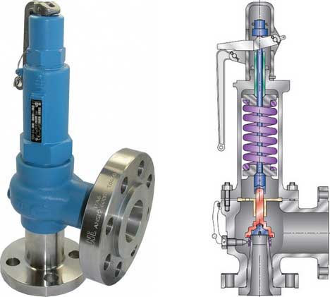
A pressure safety valve actuated by inlet static pressure and characterized by rapid opening or rapid popping action. This safety valve is tight shut-off and is for safety only. Meets ASME SEC. VIII (Not a Fulflo valve)
A spring loaded pressure relief valve, actuated by the static pressure upstream of the valve. The valve opens normally in proportion to the increase in pressure over the set pressure. (Fulflo)
A pressure relief valve characterized by rapid opening or pop-action in direct proportion to the pressure increase, depending on the application. (Fulflo)
The pressure existing at the outlet of a pressure relief valve, due to the pressure in the discharge system. The pressure can be constant or variable. It is the sum of the superimposed and build-up pressure.
The pressure existing at the outlet of the relief device at the time the device is required to operate. It is a result of pressure in the discharge system coming from another source. This pressure may be constant or variable.
Fulflo was established in 1912 and is celebrating its 100th anniversary. Located in Blanchester, OH, Fulflo was incorporated in 1933 under its present name and trademark. Patents for the original guided piston, direct acting relief valve were obtained in 1935, coinciding with the onset of fluid power systems. The need for providing large flows without excessive bulk was met by the pilot-valve-control relief valve which was patented in 1943.
Fulflo parts and valves are used in oil and gas refineries, are essential to the military, including ships and aircraft carriers, and amusement roller coaster rides.
Pressure valves regulatethe flow of gas through a pipeline by opening or closing in response to changes in the pressure of the gas, air, water, or steam flowing through the pipe. Pressure valves are commonly used on natural gas systems, propane systems, and other types of gas systems.
A pressure valve regulates the flow of gas through pipelines by opening or closing in accordance with changes in the pressure of gas flowing through the pipe, thereby maintaining a constant pressure within the pipeline.
Pressure valves work by using a spring-loaded diaphragm or electrical actuator to open or close the valve in the pipeline. As the pressure inside the pipeline rises, the diaphragm moves away from the valve seat, allowing more gas to pass through. Conversely, as the pressure falls, the diaphragms move toward the valve seat, restricting the flow of gas.
Testing a pressure valve should be done before installing it into a system. If there are leaks in the pipe, the valve will not work properly. To test a pressure valve, use a leak detector to check for leaks in the pipe. Then, turn off the main supply line and connect a gauge to the valve. Turn the valve on slowly until the pressure reaches the desired level. Once the pressure has reached the desired level, turn the valve off and wait for the pressure to drop back down to normal levels.
Pressure valve control is used in many applications, but they’re mainly found in all pneumatic and hydraulic systems. Pressure valve control has a wide range of functions that can be used to maintain a set pressure level in a part of a control loop or to keep system pressures below a desired limit.
There are many different types of pressure valve control in the industry, such as pressure relief valves, pressure reducing valves, pressure safety valves, counterbalance valves, unloading valves, and sequencing valves. Most of these pressure valves are typically closed valves, but pressure reducing valves are commonly open valves. It’s important for most of these valves to have restrictions so that the required pressure control can be achieved.
The flow must be consistent at all times in certain applications. Injuries or deaths can be caused by variations in the flow of gases. That’s why pressure control valves are so important in the processing loop.
Pressure relief valves are used to keep the pneumatic and hydraulic systems under the desired pressure value. Based on the different installation positions, pressure relief valves have different functions as below. The downstream pressure should be reduced to a constant level whenever it goes over a threshold.
A pressure relief valve is usually made of three parts: a ball/diaphragm, a spring-loaded mechanism, and a valve nozzle. A spring-loaded mechanism is placed in the valve’s housing, which is used to close the orifice. The pressure relief valve’s spring-loaded mechanism can be adjusted to change the pressure on the spring mechanism. If you want to increase the set pressure limit, just simply increase the pressure on the valve spring-load mechanism directly. If you want to decrease the set pressure limit, only decrease the pressure on the spring-load mechanism directly. A relief valve set-pressure can be specified by the manufacturer if there is no adjustability. When the set pressure is reached, the pressure overcomes the spring pressure and pushes the ball or diaphragm back opening the orifice and releasing the excess pressure. Depending on the media, it is either released into the atmosphere or discharged into it. It is possible to return to a tank or pumping circuit with compressed air.
There are two types of PRVs used in industry, one is the direct-acting pressure reducing valves, and the other type is pilot operated pressure reducing valves. The pressure reducing valves use globe type or angle type valve bodies. Most of the time, the main type of valve used in water systems is the direct acting valve, which consists of a globe-type body with a spring-loaded, heat-resistant diaphragm connected to


 8613371530291