
air compressor safety valve testing free sample
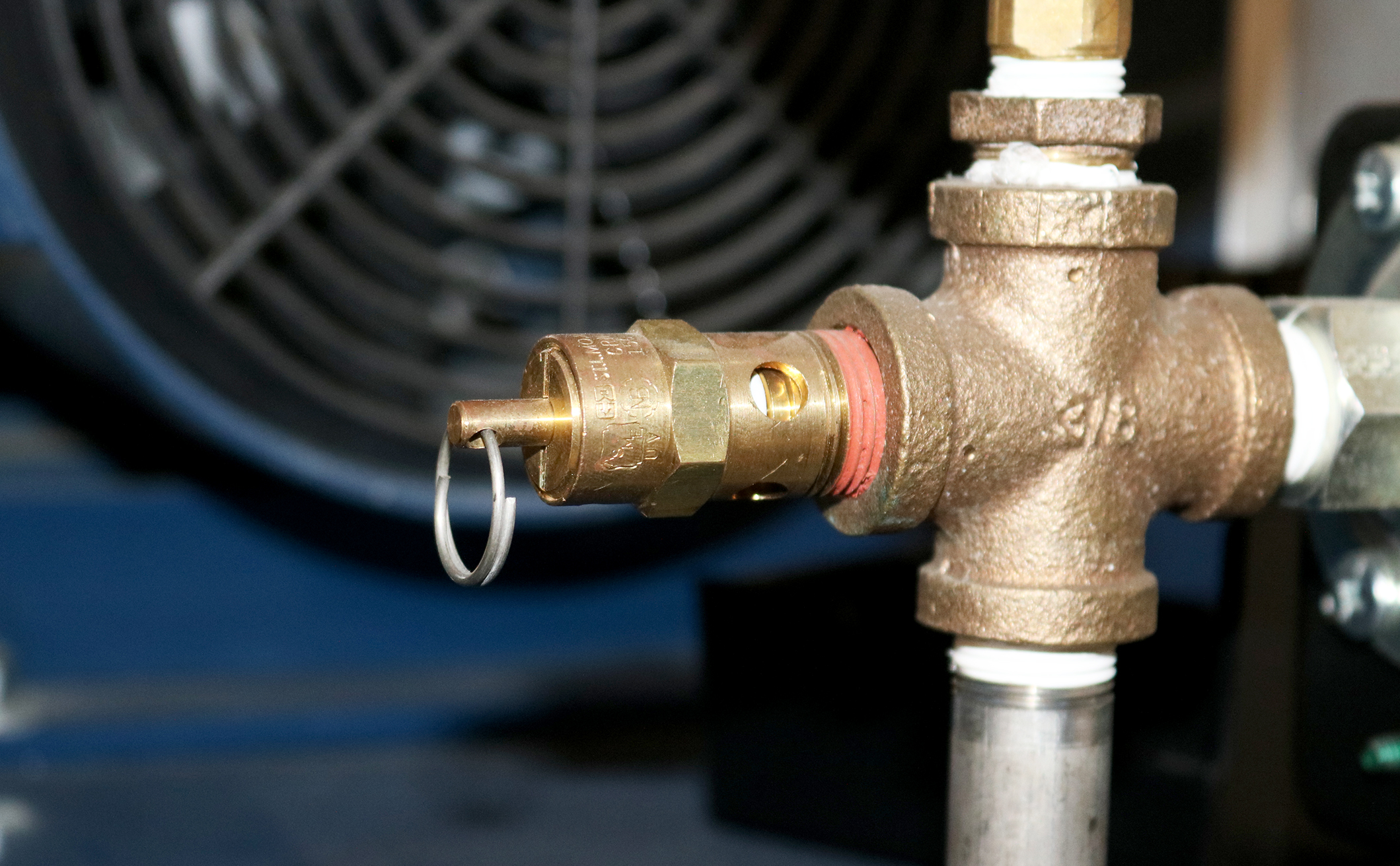
An OSHA COMPRESSED AIR SAFETY SHUT-OFF VALVES should be placed immediately after the air control shut off valve and before the hose on a compressor, and after each discharge port that a hose is connected to.
Before starting the compressor the air control valve should be closed completely. When the compressor unloads, open the air shut off control valve very slowly. Full port ball valves tend to work better than gate or butterfly type valves.
The air shut off control valve must be fully open for the OSHA COMPRESSED AIR SAFETY SHUT-OFF VALVES to work. Some portable air compressor manufacturers recommend start-up with the air control valve slightly open. In this case you may have to close the valve and reopen it slowly to the full open position, or wait for the safety shut-off valve to reset itself.
If the OSHA COMPRESSED AIR SAFETY SHUT-OFF VALVES fails to operate despite meeting all condi-tions, check the hose line for obstructions or a hose mender restricting normal air flow.
• Turn on air supply slowly (to avoid tripping OSHA safety valve). Prior to fully reaching operation conditions, the OSHA COMPRESSED AIR SAFETY SHUT-OFF VALVES should suddenly activate and stop air flow.
• If the OSHA COMPRESSED AIR SAFETY SHUT-OFF VALVE is not activated the unit should be disconnected and the lower flow range OSHA COMPRESSED AIR SAFETY SHUT-OFF VALVES should be used. This means you need to use a different valve with a lower scfm range.
• At temperatures below 40°F ensure that OSHA COMPRESSED AIR SAFETY SHUT-OFF VALVES are not subject to icy conditions which may prevent proper functioning.

You may not worry often, if at all, about whether or not your air compressor is running safely. And you really don’t have to, because compressor manufacturers do. From the pressure rating on the air storage tank to emergency stop buttons, air compressors are designed with safety in mind.
But that doesn’t mean you should never think about your compressor’s safety features. In most cases, they need to be inspected regularly to make sure they’re working properly. One key safety feature that should be inspected regularly is the air pressure relief valve (PRV), sometimes called a safety relief valve.
The pressure relief valve is a safety valve that protects the compressor component that it’s attached to from being exposed to a pressure above its rated maximum operating pressure. This rating, called the maximum working pressure (MWP), is the pressure that the vessel has been certified to continuously operate at safely.
So when a compressor is running at or below its maximum working pressure—in other words, when it’s running “normally”—the relief valve doesn’t do anything.
However, when the air pressure inside a compressor exceeds its MWP, the pressure relief valve will activate to “blow off” the excessive pressure within the compressor. Without a relief valve, the storage tank could rupture from the excessive pressure, damaging the compressor itself, possibly other property near it, and even causing injuries (or worse) to anyone standing nearby.
Before we can talk about how the air pressure relief valve works, we first need to look at how air pressure inside a compressor is managed when everything is running normally.
Under normal circumstances, the air pressure in a compressor is controlled by a pressure switch in an electro/mechanical control system or, in the case of an electronic controller, a pressure transducer and controller settings. When the cut-out set pressure for the pressure switch is reached, the compressor will stop compressing air (unload) until the cut-in set pressure is reached, at which time it will start compressing air again (load). If the pressure switch fails, the compressor would not be able to start compressing air again, or potentially worse, not be able to stop. Most compressors also have a high-pressure safety switch that should stop the compressor if the pressure exceeds the unload set point.
A pressure relief valve is a straightforward safety backup to the pressure switch and high-pressure switch, or the controller set points, should any of these components fail with the compressor running. The safety relief valve is set above the high-pressure safety switch and generally at or below the vessel’s maximum operating pressure. Inside the valve is a spring, and the pressure created by the spring’s tension keeps the valve closed under normal operating conditions. However, as the air pressure increases in pressure vessels (like the storage tank), it eventually exceeds the rated pressure of the relief valve, causing the relief valve to open and the excess pressure to be “blown off” to the atmosphere.
If the pressure relief valve fails open, air will continually vent to the atmosphere, preventing the air stream from becoming fully pressurized. The compressor should be shut down and the relief valve replaced before the compressor is restarted. The open relief valve will likely cause a loss of production and possible danger to personnel as a result of the flow of high-pressure air with flying debris and an unsafe sound level.
A pressure relief valve failing closed presents a potentially more dangerous situation. As noted earlier, the relief valve exists to allow excessive pressure to be “blown off” so that the air pressure inside the compressor’s pressure vessels don’t exceed their rated specifications. If the valve fails closed, this pressure venting can’t happen. Unless compressed air demand matches the compressed air supply, the pressure inside the compressor will continue to build. Eventually, the pressure increase would cause the storage tank to rupture, damaging the compressor and possibly causing additional damage and injury to property and people nearby.
If the relief valve is opening because the air pressure in the compressor has exceeded the valve’s pressure set point, that means the valve is working and doing what it was designed to do. But because this indicates the MWP of the compressor has been exceeded, the condition that’s causing excessive pressure should be diagnosed and corrected.
If the relief valve opening wasn’t caused by excessive pressure inside the compressor, then the valve is most likely “failing open”. Most likely, this is because the valve has become “soft” over time, i.e. the valve spring is providing less counterpressure, so it’s opening at a lower pressure than it should.
Whether the valve opened because of excessive pressure in the compressor or because the valve is failing, you should have your local air compressor distributor inspect your compressor before running it again for two reasons:
First, your distributor can determine whether the valve opened due to a failing relief valve or excessive compressors pressure and perform any needed maintenance or service to get your compressor running efficiently and safely again.
Second, regardless of why the pressure relief valve opened, replacing it may be recommended to ensure safe compressor operation, depending on the valve manufacturer. (Replacement is recommended for Sullair compressors.)
Important: Running the compressor after the relief valve has opened, regardless of the reason why it opened, can put both your property at risk of damage and people at risk of injury (or worse). While this may be obvious if the compressor is building up excess pressure, it also applies if the valve failed open. As noted above, even a valve that fails open poses some risk, and next time it could fail closed.
Given how critical a working air pressure relief valve is to the safe and efficient operation of your air compressor, you may wonder whether you need to do any regular inspecting or testing of the valve to make sure it is working. Because this can vary by manufacturer, you should consult your owner’s manual or contact your local air compressor distributor for frequency and type of inspection needed. For most Sullair compressors, inspection for damage or leakage is recommended, but testing is not recommended, as doing so may compromise the valve’s performance.
However, one thing you should do is schedule regular maintenance with your local air compressor distributor. As part of regular maintenance, a service technician can inspect the PRV and let you know it’s at an age or in a condition at which the manufacturer recommends replacement. Also, problems with the compressor’s performance, e.g. not reaching normal operating pressure, may help the service technician identify a failing relief valve after ruling out other possible causes.
When a pressure vessel like a receiver, sump tank or other storage vessel is purchased separately from the compressor, it may not be supplied with a pressure relief valve. To ensure its safe operation, you should add a PRV.
When selecting a PRV to add to the pressure vessel, you must choose a valve with a pressure set point set at or below the maximum working pressure of the vessel. You will find the MWP (and other useful information) on a tag welded to the pressure vessel. Also, flow capacity of the PRV must meet or exceed the total compressed air supplied to the vessel.
For example, if you have two compressors with capacities of 500 and 750 cfm (14.2 and 21.2 m³/min), and a pressure vessel with a maximum working pressure of 200 psi (13.8 bar), the minimum settings for a pressure relief valve would be 1250 cfm (35.4 m³/min) and a set point 200 psi (13.8 bar) or less.
Finally, when attaching the valve to the vessel, the porting must not be reduced to a size less than the size of the inlet port of the pressure relief valve.
Because the pressure relief valve is critical to the safe operation of your compressed air system, if you’re not sure how to select the correct PRV and properly and safely add it to the pressure vessel, contact your local air compressor distributor. They have the experience and expertise to ensure that the PRV is sized and installed correctly.

Safety is of the utmost importance when dealing with pressure relief valves. The valve is designed to limit system pressure, and it is critical that they remain in working order to prevent an explosion. Explosions have caused far too much damage in companies over the years, and though pressurized tanks and vessels are equipped with pressure relief vales to enhance safety, they can fail and result in disaster.
That’s also why knowing the correct way to test the valves is important. Ongoing maintenance and periodic testing of pressurized tanks and vessels and their pressure relief valves keeps them in working order and keep employees and their work environments safe. Pressure relief valves must be in good condition in order to automatically lower tank and vessel pressure; working valves open slowly when the pressure gets high enough to exceed the pressure threshold and then closes slowly until the unit reaches the low, safe threshold. To ensure the pressure relief valve is in good working condition, employees must follow best practices for testing them including:
If you consider testing pressure relief valves a maintenance task, you’ll be more likely to carry out regular testing and ensure the safety of your organization and the longevity of your
It’s important to note, however, that the American Society of Mechanical Engineers (ASME) and National Board Inspection Code (NBIC), as well as state and local jurisdictions, may set requirements for testing frequency. Companies are responsible for checking with these organizations to become familiar with the testing requirements. Consider the following NBIC recommendations on the frequency for testing relief valves:
High-pressure steam boilers 400 psi and greater – pressure test to verify nameplate set pressure every three years or as determined by operating experience as verified by testing history
High-temperature hot water boilers (greater than 160 psi and/or 250 degrees Fahrenheit) – pressure test annually to verify nameplate set pressure. For safety reasons, removal and testing on a test bench is recommended
When testing the pressure relief valve, raise and lower the test lever several times. The lever will come away from the brass stem and allow hot water to come out of the end of the drainpipe. The water should flow through the pipe, and then you should turn down the pressure to stop the leak, replace the lever, and then increase the pressure.
One of the most common problems you can address with regular testing is the buildup of mineral salt, rust, and corrosion. When buildup occurs, the valve will become non-operational; the result can be an explosion. Regular testing helps you discover these issues sooner so you can combat them and keep your boiler and valve functioning properly. If no water flows through the pipe, or if there is a trickle instead of a rush of water, look for debris that is preventing the valve from seating properly. You may be able to operate the test lever a few times to correct the issue. You will need to replace the valve if this test fails.
When testing relief valves, keep in mind that they have two basic functions. First, they will pop off when the pressure exceeds its safety threshold. The valve will pop off and open to exhaust the excess pressure until the tank’s pressure decreases to reach the set minimum pressure. After this blowdown process occurs, the valve should reset and automatically close. One important testing safety measure is to use a pressure indicator with a full-scale range higher than the pop-off pressure.
Thus, you need to be aware of the pop-off pressure point of whatever tank or vessel you test. You always should remain within the pressure limits of the test stand and ensure the test stand is assembled properly and proof pressure tested. Then, take steps to ensure the escaping pressure from the valve is directed away from the operator and that everyone involved in the test uses safety shields and wears safety eye protection.
After discharge – Because pressure relief valves are designed to open automatically to relieve pressure in your system and then close, they may be able to open and close multiple times during normal operation and testing. However, when a valve opens, debris may get into the valve seat and prevent the valve from closing properly. After discharge, check the valve for leakage. If the leakage exceeds the original settings, you need to repair the valve.
According to local jurisdictional requirements – Regulations are in place for various locations and industries that stipulate how long valves may operate before needing to be repair or replaced. State inspectors may require valves to be disassembled, inspected, repaired, and tested every five years, for instance. If you have smaller valves and applications, you can test the valve by lifting the test lever. However, you should do this approximately once a year. It’s important to note that ASME UG136A Section 3 requires valves to have a minimum of 75% operating pressure versus the set pressure of the valve for hand lifting to be performed for these types of tests.
Depending on their service and application– The service and application of a valve affect its lifespan. Valves used for clean service like steam typically last at least 20 years if they are not operated too close to the set point and are part of a preventive maintenance program. Conversely, valves used for services such as acid service, those that are operated too close to the set point, and those exposed to dirt or debris need to be replaced more often.
Pressure relief valves serve a critical role in protecting organizations and employees from explosions. Knowing how and when to test and repair or replace them is essential.

Maintaining the integrity of the pressure relief valve on an air receiver is absolutely essential when it comes to the on-going safe operation of a compressed air system. In this blog post we discuss what your responsibilities are as an owner of a pressure vessel (or air receiver) when it comes to maintaining its safe operation, and in particular what function the pressure relief valve serves and how to maintain its integrity.
An air receiver - or pressure vessel - is an important part of a compressed air system used to store compressed air as well as providing capacity during periods of peak demand. If improperly designed, installed, used or maintained, they can also be extremely dangerous and can lead to catastrophic outcomes such as fatalities, serious injuries and damage to property.
The ongoing condition monitoring of the vessel to ensure its safe operation, lies with the owner or operator of the pressure vessel. In accordance with the Standard AS/NZS 3788, depending on the size, design pressure and hazard level, an air compressor pressure vessel should be inspected externally every 2 years and internally every 4 years by a competent person.
One key component of an air receiver that needs to be inspected and certified on a regular basis is the pressure relief valve. Small but mighty, the pressure relief valve on an air receiver is a safety feature that effectively stops an air receiver from exploding if the pressure inside the vessel was to exceed its maximum allowable working pressure.
It achieves this thanks to its spring-loaded release mechanism. When the pressure inside the air receiver gets too high, the pressure pushes the pressure relief valve open allowing air to escape. Once the air receiver falls back below its maximum allowable working pressure, the pressure on the spring eases and the pressure relief valve will close. You can understand then, why maintaining the integrity of the pressure relief valve is absolutely essential for the on-going safe operation of the compressed air system.
Depending on the environment within which the compressed air system operates (for example if the compressed air system is located inside or outside), it is generally recommended that a pressure relief valve should be inspected every 12 months. Here an accredited inspector uses specialised equipment to test the functionality and effectiveness of the pressure relief valve.
In between that time - again depending on the compressed air systems operational environment - it is also generally recommended that the pressure relief valve should be manually checked for correct operation by a Competent Person. By manually lifting the valve (if possible) when the system is not pressurised, a Competent Person can check to make sure the spring is still intact and that there is not a build up of grime that could cause the valve opening to stick. Don’t forget though, that this is general advice only and you should always consult the OEMs operating instructions.
The pressure relief valve is just one area of an air receiver that needs regular attention to ensure the on-going safety of a compressed air system, but as you can see it is also a very important one. For further information and guidelines when it comes to air receiver testing and inspection click here or see the further resources section below.
Important: please note that only qualified and authorised personnel should perform maintenance tasks who have read, are conversant with and adhere to the safety instructions and section of the service manual applicable to maintenance of the piece of compressed air equipment.
KAESER AIR SERVICE Australia provides comprehensive pressure vessel inspection, testing and registration services. For more information or to request a quote phone 1800 640 611 or simply fill in the form below and we will get back to you.
Conventionally when we talk about oil lubricated screw air compressor maintenance, it is mostly about replacing consumables such as filters and lubricant on time. While these consumables have a defined usable life and have a direct effect on the efficiency and the life of the air compressor itself when not replaced on time, there are a few critical valves in the air compressor that require maintenance as well. Compressor valves directly affect the efficiency, safety, and the functionality of the screw air compressor. Let us understand some of the commonly available valves in a screw air compressor, why they need maintenance, and discuss some of the frequently asked questions about screw air compressor valves.
A screw air compressor is very similar to a human heart. While a human heart has tricuspid, pulmonary, mitral, and aortic valves, a screw air compressor has four critical valves namely air inlet, minimum pressure, blow down, and safety valves.
Air inlet valve is also commonly known as the ‘Intake valve’ which is typically assembled on the airend’s intake. The air inlet valve of a conventional fixed speed screw air compressor controls the air intake into the compressor. It remains closed when the compressor starts to lower the starting load on the main motor and when the desired working pressure is attained in the compressed air circuit and thus enabling the compressor’s motor to run without any load. In some compressors that are capable of providing a variable output by modulating the amount of air it sucks in, the inlet valve holds various opening positions to regulate the volume of air entering the compressor. The effective performance of the inlet valve directly affects the compressor’s capacity and its power consumption during load and no-load conditions.
The minimum pressure valve is typically assembled on the exit of the air-oil separation tank of a compressor. The minimum pressure valve acts as a check valve preventing back flow of compressed air into the airend, retains a minimum pressure in the compressor system for lubrication, offers a restriction to avoid a collapse of the air-oil separation filter, and ensures a suitable velocity of flow across the air-oil separator that ensures efficient air-oil separation. The effective performance of the minimum pressure valve directly affects the compressor’s lubrication, air-oil separation efficiency, and power consumption during load and no-load conditions.
The blow down valve is typically found on a dedicated exhaust line from the air-oil separation tank. The blow down valve evacuates the compressed air in the air-oil separation tank each time the compressor runs on a no-load and when the compressor shuts down to ensure there is no back pressure when the compressor starts to load next time. The blow down valve of a conventional screw compressor is typically actuated by a solenoid valve. The effective performance of the blow down valve affects the compressor’s power consumption during un-load, capacity of the compressor when running on load, and the life of the motor.
The safety valve is typically mounted directly on the air-oil separator tank. The only function of the safety valve is to blow off the compressed air in the air-oil separation tank when the pressure in the air-oil separation tank exceeds the set pressure of the safety valve and there by prevents the tank from cracking under high pressure. A malfunctioning safety valve affects the safe operation of the air compressor or results in leakage of compressed air continuously.
Though each compressor manufacturer has their own unique valve design, compressor valves in general contain moving parts such as springs, valve plates, and plungers that affect the opening and closing of the valves and rubber seals / seats that offer perfect sealing when the valves remain closed. These moving parts wear or lose their mechanical properties over a period of time and the sealing components typically ‘age’ over time and lose their effectiveness and will need to be replaced.
Compressor manufacturers typically design these components to operate efficiently for several thousand or millions of operation cycles. However, several factors such as variability in the demand pattern, sizing of the air compressor against a certain air demand, the environment in which the air compressor operates, promptness of preventive maintenance, etc. determine how long these valves efficiently operate.
Many times, it is difficult to identify a malfunctioning valve or a valve operating with worn-out parts as the compressor continues to generate air. The typical symptoms of a malfunctioning valve are loss in compressor"s capacity, increase in power consumption during load or/and unload, drop in discharge pressure, increase in oil carry-over and more load on motor. These symptoms are either difficult to notice or have other frequently common assignable causes such as air leak before suspecting the compressor valves.
Case studies show that operating a screw air compressor with a worn-out / malfunctioning valve could increase its overall power consumption by 10 - 15%. Power cost contributes to more than 75% of the compressor’s total life cycle cost over ten years and hence this is a significant impact. Unserviced valves also lower the life span of downstream accessories by half. In some cases, a malfunctioning safety valve may result in a catastrophe.
Air compressor manufacturers typically offer convenient valve maintenance kits for customers that contain the internal parts of the valve that wear or age out. Changing the valve kits is a much more sensible and economical option than changing the complete valve.
It is difficult or almost impossible to identify a malfunctioning valve unless it is opened for inspection. Hence it is absolutely mandatory that these valves are inspected for effectiveness every year and the internal moving parts replaced as a part of preventive maintenance once every year or two depending on the operating conditions of the air compressor. It is typical for compressor manufacturers to mandate a valve kit replacement once every two years as a proactive measure.
In particular, the safety valve must be inspected and certified every year per the local safety laws to ensure they are functional and efficient. Sometimes, replacing the safety valve entirely with a valid certificate for one year is more economical as the certification procedures could be equally expensive on an existing valve.
As stated before, it is challenging to identify a valve that is worn out unless it is opened and inspected, but there are a few indicators that a qualified compressor technician can use to deduct a malfunctioning valve.
Low duty cycle operation: A sophisticated screw air compressor in today’s day and age carries a convenient microprocessor-based human-machine interface that keeps track of operating hours of the compressor under load and un-load conditions and the number of load/unload counts the compressor is subjected to over a period of time. A higher un-load hours and load/unload count indicates that the air compressor is oversized against the actual air demand. This in turn indicates the air compressor ‘cycles’ frequently between load and un-load mode as opposed to running continuously on load. Every time a compressor ‘cycles’, the inlet valve, blow down valve, and minimum pressure valve is brought into play where their internals ‘actuate’. Frequent actuation of these valves results in a faster wear of the internals and hence results in shorter life.
High operating temperature: A compressor that runs on a high operating temperature affects the life of the valve’s sealing components, which causes them to ‘age’ fast.
Compressor not building pressure: If the air demand has not changed over time and the facility is relatively free of any air leakage, the air compressor is probably not delivering the rated output. There is a high probability that there is a malfunctioning valve.
Increase in compressor’s power consumption: An increase in the air compressor’s power consumption profile over a period of time where there has been no abnormal change in the air demand and usage pattern indicates an increase in either the load or un-load power. There is a high probability that this is because of a malfunctioning valve.
Based on the design philosophy adopted by the air compressor manufacturer, the oil lubricated screw air compressors could have a few more valves that are critical to functional performance that must be maintained as well. Some of the other valves frequently used in an air compressor are as follows:
Temperature control valve (also known as thermal valve) is used to regulate the flow of oil through the oil cooler based on the operating temperature.
Drain valves are used to drain lubricant at the time of lubricant change over or cleaning. Air compressors equipped with a moisture trap at the outlet of the after cooler also has a drain valve (automatic or timer based) to discharge water collected.
The presence or absence of one of these valves and the type of actuation of these valves (electronic / mechanical) depends on air compressor’s design architecture. The Operation and Maintenance Manual (OMM) and the Piping and Instrumentation Diagram (P&ID) supplied by the air compressor manufacturer are excellent resources that explain the purpose, functioning, and maintenance requirements of these valves.
Many of the air compressor valves are highly specialized and exclusive. Their designs are usually complex and some even need special tools to service them. The internal components" build quality and material selection are extremely important and proprietary. Hence it is highly critical that only genuine valve kits issued by the air compressor manufacturer are used to maintain the valves. An inferior after-market replacement will most certainly compromise the performance of the entire compressor, void the original manufacturer"s warranty of the compressor, cause consequential damage to other parts of the compressor, and above all, be a safety hazard.
In conclusion, while it is important to change the screw air compressor"s filters and lubricants on time, it is equally important to perform preventive maintenance on these critical valves in a screw air compressor as recommended by the air compressor manufacturer. While the intake valve, minimum pressure valve, safety valve, and blowdown valve are critical to the performance and safety of the compressor, there could be other valves in the compressor that are critical and need maintenance. The air compressors sizing and the environment in which it operates are crucial factors that affect the life of the air compressor. Finally, it is critical to proactively service these valves using genuine kits issued by the compressor manufacturer to enable the air compressor performs efficiently and safely.
Gershom Joel has over 15 years of experience in the compressed air field and specializes in helping industries such as Pharmaceuticals, Textile, Electronics, and Food and Beverage find compressed air solutions to meet their unique requirements. Gershom holds a Mechanical Engineering Degree from Anna University and a Masters in Business Administration from University of North Carolina.
ELGi North America, headquartered in Charlotte, NC, is a subsidiary of ELGi Equipments Limited, a leader in compressed air solutions for over 60 years. Established in 2012, ELGi North America, in conjunction with its subsidiaries, Pattons, Pattons Medical, and Michigan Air Solutions, offers a comprehensive range of compressed air products and services. Our product offering includes oil-lubricated and oil-free rotary screw and reciprocating compressors, dryers, filters, and ancillary accessories. ELGi and its subsidiaries serve multiple industry verticals spanning medical applications, pharmaceuticals, food & beverage, construction, manufacturing, and infrastructure. For more information, visit https://www.elgi.com/us/.

Safety valves and pressure relief valves are crucial for one main reason: safety. This means safety for the plant and equipment as well as safety for plant personnel and the surrounding environment.
Safety valves and pressure relief valves protect vessels, piping systems, and equipment from overpressure, which, if unchecked, can not only damage a system but potentially cause an explosion. Because these valves play such an important role, it’s absolutely essential that the right valve is used every time.
The valve size must correspond to the size of the inlet and discharge piping. The National Board specifies that the both the inlet piping and the discharge piping connected to the valve must be at least as large as the inlet/discharge opening on the valve itself.
The connection types are also important. For example, is the connection male or female? Flanged? All of these factors help determine which valve to use.
The set pressure of the valve must not exceed the maximum allowable working pressure (MAWP) of the boiler or other vessel. What this means is that the valve must open at or below the MAWP of the equipment. In turn, the MAWP of the equipment should be at least 10% greater than the highest expected operating pressure under normal circumstances.
Temperature affects the volume and viscosity of the gas or liquid flowing through the system. Temperature also helps determine the ideal material of construction for the valve. For example, steel valves can handle higher operating temperatures than valves made of either bronze or iron. Both the operating and the relieving temperature must be taken into account.
Back pressure, which may be constant or variable, is pressure on the outlet side of the pressure relief valve as a result of the pressure in the discharge system. It can affect the set pressure of the upstream valve and cause it to pop open repeatedly, which can damage the valve.
For installations with variable back pressure, valves should be selected so that the back pressure doesn’t exceed 10% of the valve set pressure. For installations with high levels of constant back pressure, a bellows-sealed valve or pilot-operated valve may be required.
Different types of service (steam, air, gas, etc.) require different valves. In addition, the valve material of construction needs to be appropriate for the service. For example, valves made of stainless steel are preferable for corrosive media.
Safety valves and relief valves must be able to relieve pressure at a certain capacity. The required capacity is determined by several factors including the geometry of the valve, the temperature of the media, and the relief discharge area.
These are just the basic factors that must be considered when selecting and sizing safety valves and relief valves. You must also consider the physical dimensions of the equipment and the plant, as well as other factors related to the environment in which the valve will operate.
Safety should be the priority in any workplace environment, whether it’s a construction site, a factory or another setting. Business leaders want to make sure their employees are safe, maintain high morale among their workforce and reduce the possibility of damaged or broken machinery. By employing practical safety measures, your company can benefit from increased uptime and fewer repair or replacement expenses.
Having safety measures in place is especially important when working with air compressors and other high-powered machinery. Compressed air should be treated with the same amount of care as other energy sources, as misuse or a lack of the proper precautions can present risks. It’s essential that all operators have the proper training, have read all instruction manuals thoroughly and understand how to mitigate safety risks and potential damage. Manuals contain an abundance of valuable information and will tell you how to keep your compressors running for longer periods without damage or injury.
There are also plenty of other resources that discuss how to maintain safety when operating pneumatic tools and air compressors. This guide will take you through the basics of using an air compressor, what to check before use, what to monitor and how to keep operators and workspaces safe to minimize air compressor dangers.
Air compressors are useful for many jobs, but they can also become dangerous when not maintained properly or misused. Compressor machines, hoses, pneumatic tools and electric connections can all pose hazards in the workplace. Air compressor accidents could potentially cause harm to workers and machinery.
What are some of the most common hazards related to air compressors? They include electrical dangers, fumes, flying particles, high pressures and high noise levels.
Flying particles and debris: Highly pressurized air and pneumatic tools can cause flying debris. If it strikes an operator, the pieces can cause bodily injury, or they can become lodged in the machine, causing damage.
High pressures:If high-pressure air is injected into the body, dangerous conditions and injuries, such as air embolism, ruptured eardrums and ruptured organs, can result.
Operators and workers can mitigate these dangers by following proper safety measures and air compressor precautions, which we will discuss later in the guide.
Depending on where you’re working, the intake air can contain pollutants and contaminants that are harmful to your health. From carbon monoxide to dust and debris, the air in the compressor collects from the surrounding space. To keep yourself safe while using the compressor unit, you must work in an area with proper airflow or natural air access, as well as protective gear, such as a respirator or dust mask.
While the likelihood of a workplace fatality due to an air compressor failure is low, it can happen in some extreme circumstances. If a compressor tank explodes, it can endanger your workers’ lives, but typically, the highest amount of danger lies with the operator. Due to the high pressures and pneumatic tools attached, operators must abide by all safety rules and regulations, including having the proper protective gear.
Every operator needs to undergo proper training and learn the relevant safety standards before using an air compressor. If you upgrade your air compressors or make any repairs, it’s essential to update operators on any changes so they know how to use the machine correctly and know what to look out for. It’s also important to check air compressor safety regulations from the Occupational Safety and Health Administration (OSHA) and ensure you’re in compliance with any that apply to your uses or machines.
The way your equipment and workspace are set up can have a significant impact on safety. Some air compressor and workspace setup tips to keep in mind include:
Component pressure ratings: Make sure that all components, including hoses, pipes and fittings, are rated for the maximum pressure of the air compressor.
Relief valves: Relief valves automatically release air if the pressure in the tank gets too high. These valves are important air compressor tank safety features, so you should never attempt to adjust, bypass or remove them.
Drain valves: If your compressor has an electric drain valve, make sure it is at least a foot and a half above the ground. Electric drain valves must be kept away from moisture.
Workspace air circulation: Intake air contains pollutants and carbon monoxide that can be hazardous to your health. For these reasons and others, it’s essential to keep your workspace circulated with clean air at all times.
Workspace humidity: It’s important to keep the humidity in your workspace from getting too high. To decrease the moisture in the air, try increasing air circulation in the workspace, operating your compressor for longer periods, using a peripheral crankcase heater or adding a dryer to your compressed air system.
Before using a compressor, you need to check various components to make sure the machine will work properly. To keep track of any issues and ensure you’ve looked at all the necessary areas, create an air compressor safety checklist for your operators to complete before each job. Some of the elements you may want to look at include:
Oil level: It’s essential to check and see if the machine has an appropriate amount of oil. Using it without an adequate amount of oil can ruin it to the point of requiring costly repairs or replacement. If it needs more oil, add oil to the reservoir but be careful not to overfill it. Also, be sure to keep oil from spilling onto the exterior of the compressor.
Fuel level:To run an air compressor, you need to have a sufficient amount of fuel. It can be a pain to have to refill in the middle of a job, as it requires you to stop, allow the compressor time to cool off and then refill the tank. Don’t refuel your air compressor when it’s on or has been shut off for only a short time. You should only conduct refuels and oil changes when the machine is cold.
Air filter:Whether you use a given compressor every day or only every once in a while, check the air filter before use. If it appears dirty or clogged, you should remove and wash it — if you have the right kind of screen — or replace it with a new filter.
Air connection:Before turning on your air compressor, make sure that it is securely connected to the air source. If the connection is weak or loose, the compressor may not perform as expected, and parts could disconnect, potentially leading to injury.
Outlets: Ensure your air compressor is only used with outlets that have the proper grounding. If you plug an air compressor into an incorrectly grounded outlet, it could damage the machine’s electrical circuitry and even cause a fire.
There are also air compression safety tips and procedures for particular parts of the compressor. Three of these components include the pressure regulation devices, air receivers and distribution lines. Each of these is significant in maintaining a healthy machine and operating it safely.
Valves:Ensure that the safety valves on your air tank are set to at least 10% or 15 psi — whichever is greater — above the operating pressure of the compressor but never higher than the air receiver’s working pressure limit. If using an air compressor in freezing temperatures, check that the safety valves are positioned in a way that prevents water from collecting inside the unit. If a valve freezes, thaw it and empty the compressor tank before reactivating the unit. The machine should also have shielded blowoff valves so sudden blowoffs don’t result in equipment damage or injury.
Air intake: The air intake should receive air only from clean, outdoor sources. Place a filter or screen at the intake valve to keep the intake air clean.
Speed: Check the manual that came with your compressor for the maximum recommended speed and ensure that you never run your compressor at speeds exceeding this level.
Draining:If your air compressor doesn’t have an automatic drain, be sure to drain the air receiver regularly so liquid does not build up inside of it.
Gauges and valves: Ensure that your air receiver has a pressure gauge and a safety valve that meets the American Society of Mechanical Engineers (ASME) standards.
Air hoses:Don’t let air hoses become bent or kinked. Check distribution lines regularly for flaws, damage and imperfections and replace any defective air lines immediately.
Operators should also take certain precautions while operating air compressors and after completing a project using an air compressor. It’s essential to remain in control of compressor units at all times. Sound footing and standing on a level surface at a safe distance from the unit is crucial as is keeping your hands, clothing and hair away from the air nozzle and tools.
While you can use compressed air for cleaning certain objects at low pressures and with a nozzle, you should never use compressed air for cleaning clothing or human skin. Don’t use compressed air to pressurize a vessel, such as to empty oil from a gearbox, as these vessels aren’t designed to handle high pressures. Don’t dry bearings using compressed air, as doing so can cause excessive rotations speeds that can cause bearings to explode.
Also, be sure to wear the proper safety gear for the job. No matter what tool you’re using for a given project, it’s vital to wear protective gear for your ears and eyes at all times. According to the Center for Disease Control, an estimated 22 million workers face exposure to potentially harmful noise every year. The risks involved with failing to wear hearing guards might not always be apparent at first, but adverse effects due to exposure to noise are often experienced later, in some cases years down the line. Personal protective equipment (PPE) to consider includes goggles, face masks, rubber or leather gloves, steel-toed shoes and leather or PVC aprons. Cotton clothing is not an effective barrier to compressed air. Cover any part of the body that is at risk of coming into contact with compressed air or flying particles.
To prevent safety issues, it’s crucial to keep an eye out for any potential issues while you’re using an air compressor. Once you start the machine and begin your work, be sure to check the following items consistently:
Surroundings: In addition to managing your own safety, keep an eye out for other workers and ensure you’re keeping the surrounding area safe. Make sure that all your hoses, cables and wires are tucked away where no one can trip on them and that you keep your area clean.
Voltage:Pay close attention to your air compressor’s voltage. If repairs are needed, power down the machine, lock and tag out all power sources and release all pressure from the compressor. If your compressor is designed for indoor use, don’t use it outdoors, as rain or wet conditions can cause electrical problems.
Air source:Be sure to check the air source itself regularly to ensure optimal performance and efficiency. The air source should be clean and dry. You can use screens or filters to clean the incoming air.
Air inlet:At the inlet, the air that goes in should be clean and free of moisture and should not exceed the maximum recommended pressure. If the maximum pressure rating of a particular tool is surpassed, it could cause various dangers, such as cracks, undue velocity or faulty pressure or output torque.
Performing preventative maintenance is essential to keeping your compressor running smoothly and safely. It can increase the longevity of your machine and improve its capabilities. Running a clean, well-kept machine will also promote the wellbeing of your workers and operators and help manage air compressor risks.
Receive the proper training:Anyone performing maintenance on an air compressor should have received the appropriate training to ensure they conduct maintenance tasks correctly and safely.
Follow the manufacturer’s recommendations: To ensure safety in maintenance and operation, it’s important to follow the care and maintenace recommendations of your compressor’s manufacturer.
Disconnect power: Before performing maintenance work, shut off the machine and disconnect it from all power sources. Lock open the electrical switch for the compressor and tag it so no one starts it by mistake.
Clean the unit properly:Cleaning your air compressor regularly will improve its performance and extend its life. When it comes to cleaning carbon remnants from the various parts of an air compressor, it’s safe to use soapy water or a lye solution, but you should never use anything flammable, such as kerosene. Following every cleaning, completely purge the air system.
Lubricate properly:Don’t use oils with low flash points to lubricate compressor parts. These oils could combust due to the high temperatures produced by air compressors during operation. It’s essential, however, to keep parts lubricated with the proper oils and to avoid over-lubrication to prevent corrosion.
Take steps to prevent rust: One of the most dangerous possibilities when it comes to air compressors is a rusty tank. Rust increases the unit’s chances of combusting, putting anyone nearby in danger. To prevent rust due to the accumulation of liquid, use the underside valve to drain the tank daily. If a tank becomes rusted, don’t attempt to repair it. A rusted tank requires replacement.
Handle tools safely:Before you install, remove, fine-tune or perform any kind of maintenance on your pneumatic impact tools or accessory parts, shut off the source of air, bleed the air pressure and disengage the air hose.
Report faulty equipment immediately:If you notice that repair work is needed that goes beyond regular maintenance, tag out the machine so no one uses it. Then, report the issue as quickly as possible so the machine can be repaired.
Although proper maintenance can help extend the life of your air compressor, you may still occasionally need to troubleshoot issues. Follow these compressed air safety tips when troubleshooting your equipment:
Shut down your compressor:Turn off your compressor, disconnect it from power and bleed any remaining air pressure before doing any troubleshooting or repair work. Make sure that the shutoff valve is always within reach in case something goes wrong during operation.
Follow safety procedures for hose malfunctions:If a hose malfunctions or comes apart at the coupling, you can prevent whipping with two components. One is an air fuse of the proper size, which you should install in the hose upstream. The other is a whip-inhibiting device that is placed along the coupling of a hose. If an air hose does start whipping around uncontrollably or another similar air hose problem occurs, don’t try to stop and control it by grabbing the hose. To prevent injury, turn off the air source before touching the hose.
Use reliable parts: If a component becomes damaged or needs to be replaced for any reason, use only reliable, high-quality parts that are the correct size, material and type for your machine. Using the wrong parts or low-quality components can result in decreased compressor performance, damage to your equipment and safety hazards.
As one of the world’s leading sellers of compressed air products for nearly 100 years, Quincy Compressor offers an array of machines and parts for many industries. With our one-of-a-kind offers and round-the-clock support, we’ve supplied and serviced businesses in the automotive, manufacturing and construction sectors, among others.
People have various uses for compressed air, and at Quincy, we’ve got them all covered. With Quincy, there’s no application too demanding for our top-of-the-line products to handle with utmost ease and maximum efficiency. Everyone who shops with us receives support from our authorized partners, day or night, as well as industry-leading warranties on select compressor products.
If you’re in the market for compressed air devices or related equipment, explore our website, where you can download whitepapers for more information on our wide range of products. You can also contact your local authorized Quincy Compressor distributor for air compressor sales and service in your area.
In order to ensure that the maximum allowable accumulation pressure of any system or apparatus protected by a safety valve is never exceeded, careful consideration of the safety valve’s position in the system has to be made. As there is such a wide range of applications, there is no absolute rule as to where the valve should be positioned and therefore, every application needs to be treated separately.
A common steam application for a safety valve is to protect process equipment supplied from a pressure reducing station. Two possible arrangements are shown in Figure 9.3.3.
The safety valve can be fitted within the pressure reducing station itself, that is, before the downstream stop valve, as in Figure 9.3.3 (a), or further downstream, nearer the apparatus as in Figure 9.3.3 (b). Fitting the safety valve before the downstream stop valve has the following advantages:
• The safety valve can be tested in-line by shutting down the downstream stop valve without the chance of downstream apparatus being over pressurised, should the safety valve fail under test.
• When setting the PRV under no-load conditions, the operation of the safety valve can be observed, as this condition is most likely to cause ‘simmer’. If this should occur, the PRV pressure can be adjusted to below the safety valve reseat pressure.
Indeed, a separate safety valve may have to be fitted on the inlet to each downstream piece of apparatus, when the PRV supplies several such pieces of apparatus.
• If supplying one piece of apparatus, which has a MAWP pressure less than the PRV supply pressure, the apparatus must be fitted with a safety valve, preferably close-coupled to its steam inlet connection.
• If a PRV is supplying more than one apparatus and the MAWP of any item is less than the PRV supply pressure, either the PRV station must be fitted with a safety valve set at the lowest possible MAWP of the connected apparatus, or each item of affected apparatus must be fitted with a safety valve.
• The safety valve must be located so that the pressure cannot accumulate in the apparatus viaanother route, for example, from a separate steam line or a bypass line.
It could be argued that every installation deserves special consideration when it comes to safety, but the following applications and situations are a little unusual and worth considering:
• Fire - Any pressure vessel should be protected from overpressure in the event of fire. Although a safety valve mounted for operational protection may also offer protection under fire conditions,such cases require special consideration, which is beyond the scope of this text.
• Exothermic applications - These must be fitted with a safety valve close-coupled to the apparatus steam inlet or the body direct. No alternative applies.
• Safety valves used as warning devices - Sometimes, safety valves are fitted to systems as warning devices. They are not required to relieve fault loads but to warn of pressures increasing above normal working pressures for operational reasons only. In these instances, safety valves are set at the warning pressure and only need to be of minimum size. If there is any danger of systems fitted with such a safety valve exceeding their maximum allowable working pressure, they must be protected by additional safety valves in the usual way.
In order to illustrate the importance of the positioning of a safety valve, consider an automatic pump trap (see Block 14) used to remove condensate from a heating vessel. The automatic pump trap (APT), incorporates a mechanical type pump, which uses the motive force of steam to pump the condensate through the return system. The position of the safety valve will depend on the MAWP of the APT and its required motive inlet pressure.
This arrangement is suitable if the pump-trap motive pressure is less than 1.6 bar g (safety valve set pressure of 2 bar g less 0.3 bar blowdown and a 0.1 bar shut-off margin). Since the MAWP of both the APT and the vessel are greater than the safety valve set pressure, a single safety valve would provide suitable protection for the system.
Here, two separate PRV stations are used each with its own safety valve. If the APT internals failed and steam at 4 bar g passed through the APT and into the vessel, safety valve ‘A’ would relieve this pressure and protect the vessel. Safety valve ‘B’ would not lift as the pressure in the APT is still acceptable and below its set pressure.
It should be noted that safety valve ‘A’ is positioned on the downstream side of the temperature control valve; this is done for both safety and operational reasons:
Operation - There is less chance of safety valve ‘A’ simmering during operation in this position,as the pressure is typically lower after the control valve than before it.
Also, note that if the MAWP of the pump-trap were greater than the pressure upstream of PRV ‘A’, it would be permissible to omit safety valve ‘B’ from the system, but safety valve ‘A’ must be sized to take into account the total fault flow through PRV ‘B’ as well as through PRV ‘A’.
A pharmaceutical factory has twelve jacketed pans on the same production floor, all rated with the same MAWP. Where would the safety valve be positioned?
One solution would be to install a safety valve on the inlet to each pan (Figure 9.3.6). In this instance, each safety valve would have to be sized to pass the entire load, in case the PRV failed open whilst the other eleven pans were shut down.
If additional apparatus with a lower MAWP than the pans (for example, a shell and tube heat exchanger) were to be included in the system, it would be necessary to fit an additional safety valve. This safety valve would be set to an appropriate lower set pressure and sized to pass the fault flow through the temperature control valve (see Figure 9.3.8).

This section tells you about air brakes. If you want to drive a truck, bus, or pull a trailer with air brakes, you need to read this section. If you want to pull a trailer with air brakes, you also need to read Section 6: Combination Vehicles in this handbook.
Air brakes use compressed air to make the brakes work. Air brakes are a good and safe way of stopping large and heavy vehicles, but the brakes must be well maintained and used properly.
CDL Air Brake Requirements. For CDL purposes, a vehicle’s air brake system must meet the above definition and contain the following, which will be checked during the vehicle inspection test:
If the vehicle you use for your road test does not have these components, your vehicle will not be considered as having an air brake system and you will have a “No Air Brakes” (“L”) restriction on your CDL.
A full service brake application must deliver to all brake chambers not less than 90 percent of the air reservoir pressure remaining with the brakes applied (CVC §26502).
The air compressor pumps air into the air storage tanks (reservoirs). The air compressor is connected to the engine through gears or a v-belt. The compressor may be air cooled or cooled by the engine cooling system. It may have its own oil supply or be lubricated by engine oil. If the compressor has its own oil supply, check the oil level before driving.
The governor controls when the air compressor will pump air into the air storage tanks. When air tank pressure rises to the “cut-out” level (around 125 pounds per-square-inch or “psi”), the governor stops the compressor from pumping air. When the tank pressure falls to the “cut-in” pressure (around 100 psi), the governor allows the compressor to start pumping again.
Air storage tanks are used to hold compressed air. The number and size of air tanks varies among vehicles. The tanks will hold enough air to allow the brakes to be used several times, even if the compressor stops working.
Compressed air usually has some water and some compressor oil in it, which is bad for the air brake system. The water can freeze in cold weather and cause brake failure. The water and oil tend to collect in the bottom of the air tank. Be sure that you drain the air tanks completely. Each air tank is equipped with a drain valve in the bottom. There are 2 types:
Some air brake systems have an alcohol evaporator to put alcohol into the air system. This helps to reduce the risk of ice in air brake valves and other parts during cold weather. Ice inside the system can make the brakes stop working.
Check the alcohol container and fill up as necessary. (every day during cold weather). Daily air tank drainage is still needed to get rid of water and oil (unless the system has automatic drain valves).
A safety relief valve is installed in the first tank the air compressor pumps air to. The safety valve protects the tank and the rest of the system from too much pressure. The valve is usually set to open at 150 psi. If the safety valve releases air, something is wrong. Have the fault fixed by a mechanic.
You engage the brakes by pushing down the brake pedal (It is also called a foot valve or treadle valve). Pushing the pedal down harder applies more air pressure. Letting up on the brake pedal reduces the air pressure and releases the brakes. Releasing the brakes lets some compressed air go out of the system, so the air pressure in the tanks is reduced. It must be made up by the air compressor. Pressing and releasing the pedal unnecessarily can let air out faster than the compressor can replace it. If the pressure gets too low, the brakes will not work.
S-cam Brakes. When you push the brake pedal, air is let into each brake chamber. Air pressure pushes the rod out, moving the slack adjuster, thus twisting the brake camshaft. This turns the S-cam (it is shaped like the letter “S”). The S-cam forces the brake shoes away from one another and presses them against the inside of the brake drum. When you release the brake pedal, the S-cam rotates back and a spring pulls the brake shoes away from the drum, letting the wheels roll freely again. See Figure 5.2.
Disc Brakes.In air-operated disc brakes, air pressure acts on a brake chamber and slack adjuster, like S-cam brakes. But instead of the S-cam, a “power screw” is used. The pressure of the brake chamber on the slack adjuster turns the power screw. The power screw clamps the disc or rotor between the brake lining pads of a caliper, similar to a large c-clamp.
All vehicles with air brakes have a pressure gauge connected to the air tank. If the vehicle has a dual air brake system, there will be a gauge for each half of the system (or a single gauge with two needles). Dual systems will be discussed later. These gauges tell you how much pressure is in the air tanks.
This gauge shows how much air pressure you are applying to the brakes. (This gauge is not on all vehicles.) Increasing application pressure to hold the same speed means the brakes are fading. You should slow down and use a lower gear. Brakes that are of adjustment, air leaks, or mechanical problems can also cause the need for increased pressure.
A low air pressure warning signal is required on vehicles with air brakes. A warning signal you can see must come on when the air pressure in the tanks falls between 55 and 75 psi (or 1/2 the compressor governor cutout pressure on older vehicles). The warning is usually a red light. A buzzer may also come on.
Drivers behind you must be warned when you put your brakes on. The air brake system does this with an electric switch that works by air pressure. The switch turns on the brake lig


 8613371530291