
gas line safety valve factory

If you have been searching for a safety release valve that you can use to reduce short-term pressure surges successfully and diminish the effects of gas leaks, this is the product for ...
... regulators have safety valves which will slam shut in the event of emergencies, such as the gas reaching too high a pressure level. The valve works to protect any fittings ...
This product has hydraulically actuated class A gas safety valves to EN 161 used for automatic shut-off. It shuts off when unstimulated for gas and air, ...
The S 104 Safety Shut Off valve is mainly used to avoid any damage to components as well as to avoid too high or too low pressure in the gas train. This could cause high financial losses ...
The S50 Safety Shut Off valve is mainly used to avoid any damage to components as well as to avoid too high or too low pressure in the gas train. This could cause high financial losses ...
The S100 Safety Shut Off valve is mainly used to avoid any damage to components as well as to avoid too high or too low pressure in the gas train. This could cause high financial losses ...
... Pressure Safety Valve + Rupture Disk is protected and may be utilized autonomously as essential security gadgets or in conjunction. There are 3 possible combinations. The first combinations ...
It"s a Safety valve in according with Directives ATEX 20K/34/EU. Technical Norm Fire Prevention 41/256 31/10/2019. d.P.R. 10/520 19/03/1955 and subsequent amendments.
130 Series Safety valves are also available as Relief valves. Relief valves, identified by the letter R after the type number, are devices with an operational function, ...
V651 Series safety relief valves are produced as safety and relief type. Safety valves are pressure relief elements used to evacuate excessive pressure ...
PVS type slam shut valves are pilot-operated relief valves in which the opening and the closing of the main plug is controlled by a pilot device which is very ...
This range of spring loaded conventional and balanced safety relief valves is specifically designed for overpressure protection of unfired pressure vessel (ASME Section VIII application). ...
The EMERSON BM7 SERIES is a disk slam-shut valve characterized as automatic isolating elements, which are suitable for installation as safety devices in regulating stations. This device has a high operation ...
... control and regulate the gas, air flow to burners and other combustion devices. HMV is a unique safety valve that can be supplied for the requiremen of handling higher ...
Type 50 is a safety valve for universal use. It can be used for nearly any industrial application, e.g. in shipping and pipeline construction, the chemical and petrochemical industries, ...
The RIEGER Safety valve Type SH prevents excessive pressure in steam and gaseous media in plant components and tanks. The set pressure is generally higher than the operating pressure of the system.
... sewage, gas, glycol, diathermic oil, industrial water, steam and other natural and aggressive media, depending on theresistance of materials usedfor the construction ofthe valve.
With DirectIndustry you can: Find the product, subcontractor or service provider you need | Find a nearby distributor or reseller| Contact the manufacturer to get a quote or a price | Examine product characteristics and technical specifications for major brands | View PDF catalogues and other online documentation
The S50 Safety Shut Off valve is mainly used to avoid any damage to components as well as to avoid too high or too low pressure in the gas train. This could cause high financial losses and/or injured ...
The S100 Safety Shut Off valve is mainly used to avoid any damage to components as well as to avoid too high or too low pressure in the gas train. This could cause high financial losses and/or injured ...
The main purpose of the safety relief valve SL 5 is to relieve small pressure increases and quantities in the controlled system to prevent the safety shut-off valve from ...
130 Series Safety valves are also available as Relief valves. Relief valves, identified by the letter R after the type number, are devices with an operational function, ...
Cryogenic Safety Valves Type 06011 is made with stainless steel. It is provided as a safety device for protection against thermal expansion in pipework and parts of facilities. ...
With DirectIndustry you can: Find the product, subcontractor or service provider you need | Find a nearby distributor or reseller| Contact the manufacturer to get a quote or a price | Examine product characteristics and technical specifications for major brands | View PDF catalogues and other online documentation
WITT is a manufacturer of Pressure relief valvesor Safety relief valves for technical gases. They are designed to protect against overpressure by discharging pressurized gases and vapors from pipelines, pressure vessels and plant components. Safety relief valves (SRV) are often the last line of defense against explosion – and such an explosion could be fatal. Other common names for safety relief valves are pressure relief valve (PRV), safety valve, pressure safety valve, overpressure valve, relief valve or blow-off valve.
WITT safety valves are very precise. They are individually preset to open at a predetermined pressure within the range 0.07 to 652 Psi. Their small size and orientation-independent installation allow a wide range of connection options. WITT relief valves also stand out due to their high blow-off flow rates of up to 970m³/h. They can be used within a temperature range of -76° F to +518°F and even with very low pressures.
For maximum safety, WITT undertakes 100 % testing of each safety relief valve before it is delivered. In addition, WITT offers individual testing of eachsafety valveby the TÜV, with their certificate as proof of the correct set pressure.
WITTsafety relief valvesare direct-acting, spring-loaded valves. When the preset opening pressure is reached, a spring-loaded element in the valve gives way and opens, and the pressure is relieved. Once the pressures are equalized, the valve closes automatically and can be reactivated any time the pressure rises again. Depending on the application and the nature of the gas, the safety relief valvescan either discharge to atmosphere, or via a connected blow-off line. The opening pressure of the safety valves is preset by WITT at the factory according to the customer’s requirements.
Safety relief valvesare used in numerous industries and industrial applications where, for example, gases pass through pipelines or where special process vessels have to be filled with gas at a certain pressure.
These include, among other things:Pipeline, plant and container constructionIndustrial furnace constructionInsulators and reactors (e.g. “glovebox” systems)hydrogen-powered vehiclesAdditive manufacturing (3D printer)
For most industrial applications using technical gases, brass is usually the standard material of construction of thesafety relief valvebody/housing. For the use of pressure relief valves with aggressive and corrosive gases, the housings are made of high-quality stainless steel (1.4541/AISI 321, 1.4404/AISI 316L, 1.4305/AISI 303 or 1.4571/AISI 316Ti). The use of aluminium as a housing material is also possible.
Depending on the type of gas used and individual customer requirements, various sealing materials and elastomers are available to ensure the safety of your systems under even the most difficult conditions.
WITT pressure relief valves are available with different connections. In addition to the standard versions with the usual internal or external threads, special versions with KF or CF flanges, VCR or UNF threads can also be ordered. Special adapters for connecting the safety relief valve to a blow-off line are also available.
Flow Safe is a manufacturer of spring-operated and pilot-operated high-performance pressure relief devices. The Flow Safe product line is specifically designed for applications in Natural Gas Distribution, Pipeline, Aerospace, Marine, Industrial Gasses and other liquid and gas process applications.
Due to the continued escalation of raw materials as well as additional COVID-related costs, Flow Safe is announcing a list price increase effective Aug. 2, 2021. The increase will be between 8% and 10% depending on the product line.
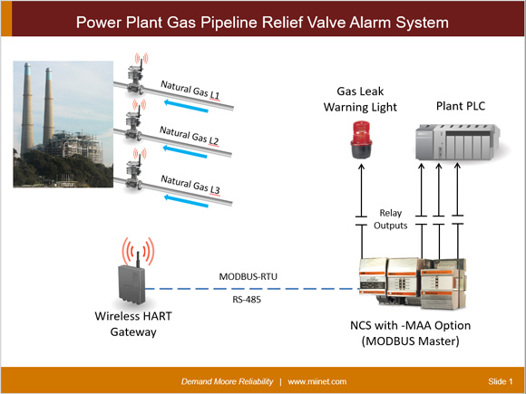
A Power Plant in the U.S. Northeast needed to monitor three safety relief valves on gas lines into their power plant. An alarm is required on each valve in case any of these relief valves experience a release of natural gas. Because it would have been too costly to run several new wires out to these valves from the control room PLC, they opted to implement a wireless solution coupled with a field mounted NCS Net Concentrator System.
Each relief valve was retrofitted with a WirelessHART positioner/monitor to relay its status back to the WirelessHART gateway. The NCS, acting as a MODBUS RTU Master, gathered the relief valve status from the gateway over RS-485 and provided the local alarming and annunciation. Alarms for each relief valve were quickly configured with easy-to-use web pages within the NCS. If any valve reported a leak, the NCS sent relay outputs to a flashing beacon and a PLC that was tied to the plant’s main SCADA and safety system.

While it"s possible to manually shut off your natural gas, the following specialized valves are available that can automatically shut off your service in case of an emergency:
Earthquake natural gas shut-off valve (also known as a seismic natural gas shut-off valve) automatically shuts off your natural gas service when an earthquake of a sufficient magnitude occurs at your home.
An excess-flow valve (EFV) automatically closes and restricts the flow of natural gas in the event an underground pipe is damaged or if there is a significant increase in the flow of natural gas to the meter.
If you want to have an earthquake natural gas shut-off installed, or are required to have one by your insurance company or the local Department of Building and Safety, the valve must be installed on your house line.
If installation requires natural gas service closure, you"ll need to contact us to shut off the service and restore service when installation is completed. Natural gas service shut off and restoration of service orders can be scheduled by contacting us at 1-800-427-2200.
Under the regulations of the California Public Utilities Commission (CPUC), General Order 112-E, only SoCalGas® or its certified contractors are authorized to operate the natural gas service shut-off valve.
When you hire a qualified professional to install your earthquake valve, you"ll need to make sure that the valve is installed on your house line, not on SoCalGas" facilities. SoCalGas" facilities include all of the pipe fittings installed and maintained by SoCalGas, up to and including the last elbow or tee connecting to your house line. See the diagram below for to see where your house line starts.
All unauthorized valve installations found on SoCalGas" facilities will be removed. In addition, earthquake valves are not permitted in utility curb meter vaults.
If an earthquake or other significant event causes your earthquake shut-off or excess-flow valve to close, you can follow the manufacturer"s instructions for resetting the valve so that natural gas flows again. However, we recommend that you contact a qualified professional or SoCalGas to reset the valve, and to perform a safety check of your natural gas appliances before they are placed back in operation to verify that no natural gas leaks exist, and to re-light your pilot lights.
Remember that following a major emergency it may take many days or even weeks before someone can come to your location. (SoCalGas charges a fee to reset valves and re-light pilot lights when your earthquake shut-off valve has closed due to a non-earthquake occurrence.)
Price: The cost of the valve is going to vary based on the type and size of the valve, as well as the installation requirements and the company installing it.
Choosing a valve: In order to choose the right valve size and manufacturer, contact your local Department of Building and Safety to find out their earthquake valve requirements.
Where to buy a valve: You can purchase an earthquake valve at supply retailers, licensed plumbing contractors, or directly from the valve manufacturer.
Using a contractor: You can hire a qualified professional to install the earthquake or excess-flow valve on your house line. SoCalGas will not install a valve for you.
Effective February 10, 2002, California Public Utility Commission (CPUC) Decision 01-11-068 prohibits installation of an earthquake valve on SoCalGas" facilities. In addition, SoCalGas no longer installs earthquake shut-off valves for its customers, and does not allow any customer owned equipment, including excess-flow valves, be installed on SoCalGas" facilities.
If you have an earthquake valve that was installed by SoCalGas or one of its authorized contractors on or before the February 10, 2002 cutoff date, that is located on SoCalGas" facilities, with proper documentation your installation may be allowed to remain in place. Authorized contractors are those who participated in SoCalGas" earthquake program and were trained by SoCalGas to work on their facilities.
Additional information regarding earthquake valves and natural gas service restoration after a valve activates can be found in Tariff Book, Rule 10, Section G, "Earthquake Valve Service."
An Excess Flow Valve, or EFV, is a safety device installed on natural gas distribution pipelines to automatically close and restrict the flow of natural gas in the event an underground pipe is damaged or if there is a significant increase in the flow of natural gas to the meter. These conditions are typically caused by digging or construction but can also be caused by damage to your natural gas meter by a vehicle impact.
EFV can reduce the risk of explosions, fires, and personal injury because they close or restrict any unplanned or excessive natural gas flow. Installation of an EFV will not protect a customer from household appliance malfunctions, small punctures in underground pipelines, and pipeline damage from earthquakes or flooding. It is
important to understand that an EFV does not shut off the flow of natural gas completely. Some leakage may still occur resulting in a hazardous condition.
An EFV is installed on the service pipeline that runs underground between the natural gas main (usually located in or near the street, alley or easement) and the SoCalGas® meter on the customer’s property).
The best way to prevent damage to a natural gas pipeline due to digging is to call 811, the Underground Service Alert program, at least two working days before digging. Underground Service Alert will coordinate with SoCalGas to mark the locations of buried utility-owned lines - absolutely FREE.
If you are interested in having an EFV installed on the service pipeline serving you[1], please call SoCalGas at 1-800-427-2200. SoCalGas will first check to see if your service already has an EFV installed and, if not, an estimate to install the EFV will be provided. The cost to install an EFV can vary widely depending on site specific conditions and can range from $2,500 to $5,000 or more.
If you decide to have an EFV installed, we will coordinate with you to schedule the installation (note that it is possible that natural gas service will be interrupted to install the EFV). The construction crew will dig around the natural gas line in order to install the EFV and when the job is complete natural gas service will be restored (if it was shut off). If paving or concrete needs repair that work will be scheduled at a later date.
The bulldozer was clearing land outside a day care center in Hapeville, Ga., when it broke open a buried 1-inch pipeline. The escaping gas ignited into a fireball that killed nine people, including seven children settling down for their afternoon naps.
That was 1968. Since then, there have been at least 270 similar accidents across the country that could have been prevented or made less dangerous by a valve that cuts off leaking gas and costs as little as $10-$15 for homes and small businesses and $200-$300 for larger buildings, an Associated Press investigation found.
Yet nearly 90 percent of the nation"s gas service lines aren"t fitted with the valves. Despite persistent government recommendations, the gas industry has argued that they are unreliable and cost too much to install — $207 million over 50 years in one industry-commissioned study, more than $1 billion in another estimate.
In the meantime, the accidents continued: Since Hapeville, at least 67 people have been killed and more than 350 hurt in accidents where the valves could have helped but weren"t installed. Six people were killed in a Minnesota store blast in 1972. A 25-story Manhattan building was destroyed in 1974, injuring 70 people. Four people died and six buildings were leveled in an explosion in 1998 in St. Cloud, Minn.
"There were lives lost that did not need to be lost," said Robert Hall, deputy director of the National Transportation Safety Board, which is responsible for investigating pipeline accidents.
MPR News is not just a listener supported source of information, it"s a resource where listeners are supported. We take you beyond the headlines to the world we share in Minnesota. Become a sustainer today to fuel MPR News all year long.
The NTSB recommended the valves 16 times, but only in 2009, under pressure from Congress, was a rule approved — to make the devices mandatory only on lines leading to new, single-family homes. Now, regulators are considering expanding that to new or replaced pipelines serving millions of multifamily homes and commercial buildings. And the utilities are objecting.
"NTSB has made excess flow valves some kind of holy war where they think everything should have a valve on it," said Don Stursma, an official at the Iowa Utilities Board who sits on an advisory board to the Pipeline and Hazardous Materials Safety Administration.
The valves are designed to trip automatically when there is a break in a service line, the narrow-diameter pipes that serve individual homes and businesses. A sudden rush of escaping gas pushes a small, spring-loaded stopper inside the valve, plugging the line.
Without them, gas can leak unchecked into a building or house, pooling until an ignition source — turning on the stove, a pilot light in the water heater, even an electrical spark from a cellphone — triggers an explosion or fire.
That includes 148 cases the U.S. Transportation Department said could have been averted or diminished if valves were in place. The department released details on those accidents in response to a public records request from the AP. Applying the agency"s criteria, the AP found 39 more. Another 84 cases were identified by NTSB investigators or mentioned in Transportation Department studies.
There are more than 66 million natural gas service lines in the U.S., but only about one in 10 had excess flow valves, according to the government"s most recent data. Almost 46 million new service lines have been installed since 1970 — about 39 million without excess flow valves. That"s about 39 million "missed opportunities," as Hall put it.
The federal pipeline safety agency, which sets pipeline rules, announced last year that it was considering requiring the valves for multifamily dwellings and commercial buildings. The agency believes the 2009 mandate for safety valves on single-family homes "only partially addressed" the NTSB"s recommendations, agency spokeswoman Jeannie Layson said in a written statement.
Before the agency decides whether to go ahead with new rules, officials want to survey companies about how much it might cost them to place excess flow valves on service lines for buildings along with new, single-family homes, Layson said.
Manufacturers and utilities say the cost per valve could be as low as $10-$15 for homes, retail businesses and restaurants. For larger buildings, such as large commercial or small industrial businesses and institutional buildings such as libraries, the cost can climb to $200-$300, according to GasBreaker Inc., a Pennsylvania-based manufacturer.
— In 1974, consultants to the Transportation Department said installing valves on new lines was not only economically and technically feasible, but would improve public safety. They recommended more study, however.
— In 1991, an industry-commissioned study put the price tag at $207 million over 50 years to outfit new and renewed lines, an estimate that included the price of the device, its installation and the potential cost of digging up pipes to repair bad valves.
— In 1995, when Congress was debating whether to mandate the valves, an industry executive estimated the cost would top $1 billion. The proposal was dropped.
All sides in the debate agree that installing the valves retroactively would be too expensive. But NTSB"s Hall said industry resistance has blocked the valves" installation even on new service lines where costs would be largely limited to the price of the device.
The American Gas Association and several other industry groups warn there are still too many unknowns, including how the valves would function in large-scale settings where demand for gas could jump in different seasons.
The association said a federal pipeline safety agency study "grossly understates the economic, technical, and operational complexities" of broadening the valves" use to large-volume customers such as hotels, restaurants and hospitals.
The association would support valves on certain larger customers that draw a fixed amount of natural gas, vice president Christina Sames wrote. She cautioned against a broader mandate, saying that schools, hospitals, restaurants and some apartments that can draw varying amounts of gas are "critical" customers where an inadvertent trip of a valve would threaten safety or hurt business.
The dispute over valves for service lines comes amid a broader debate over pipeline safety sparked by a 2010 explosion in San Bruno, Calif. that killed eight people and a blast last year in Allentown, Penn. that killed five. Those accidents also triggered calls for emergency shut-off valves, but they involved larger pipelines not covered in the government"s proposed service line rules.
Individual utilities said they should be trusted to decide when and where to install the service line valves. A device manufacturer, however, said some utilities" reluctance stems from a lack of experience with the devices.
"We have sold millions of these and, if these problems were a reality, we as a manufacturer would be called to task on them," GasBreaker CEO John McGowan Jr. said.
San Francisco-based Pacific Gas & Electric Co., one of the nation"s largest gas companies, has installed excess flow valves on fewer than 3 percent of its 3.4 million service lines, government data from 2011 shows.
Anthony Earley, PG&E"s CEO, said he objects to widespread use of valves because customers can be inconvenienced if gas is shut off in response to a false trigger. "Once you trip a gas valve and shut off gas, you can"t just turn the gas back on," he said.
Steve Miner, a manager of operations at Vermont Gas Services, said the valves are impractical at schools or hospitals because they can limit gas flow, possibly "starving" large boilers or furnaces that need a steady flow to run properly. Beyond those cases, Miner said, he would have "no problem" with expanding the mandates.
"I think they are the best thing out there," Miner said. "I"m the one who has to go on these emergency calls and it"s a nice feeling when you know the (excess flow valve) is on that service."
When a crew of cable installers in St. Cloud, Minn., struck a downtown gas line in 1998, the pipe leaked for 39 minutes until something ignited the gas. A pizzeria, apartment units, a law office and a bar were destroyed. Among the dead was Robert Jacobs, a gas company worker and father of two.
"I would think putting those valves on lines going to apartments or businesses would be very important, but the companies say it"s too expensive," said his wife of 23 years, Jean Jacobs. "But how do you put a price tag on a life?"

BILLINGS, Mont. — The Obama administration moved Wednesday to significantly expand a requirement for utilities to install inexpensive safety valves on gas lines across the United States after deadly fires and explosions going back decades that officials and safety advocates said could have been avoided.
The Transportation Department proposal would cover new or replaced natural gas lines serving multifamily dwellings, small businesses and homes not already covered under a 2009 mandate.
The National Transportation Safety Board and other safety advocates have pressed for years to broaden requirements for so-called excess flow valves. The devices cost about $30 apiece for residential use, according to officials, and are designed to automatically shut off the flow of gas when a line is ruptured.
An Associated Press investigation in 2012 uncovered more than 270 accidents dating to 1968 that could have been averted or made less dangerous if the valves had been in place. A cracked cast-iron pipe in Allentown caused an explosion in February 2011 that killed five people and destroyed half a block of row homes.
Officials stressed that the valves won"t prevent lines from being ruptured, such as when a backhoe doing excavation work slices through a gas pipeline servicing a house. But by limiting the amount of gas that escapes, the valves can prevent a buildup of fuel that can contribute to explosions or fires.
"This important action will add extra protections to communities serviced by the nation"s largest network of pipelines," Transportation Secretary Anthony Foxx said in a statement. He said the valves can have "a significant impact in reducing the consequences of natural gas leaks."
Federal transportation officials said if the valves had been in place, they could have averted at least eight accidents that killed 10 people since 1998.
As utilities across the country dig up their old, cast-iron and plastic gas lines over the coming years, the rule would ensure they are replaced with safer lines that can be shut off more easily, said Carl Weimer, executive director of the Pipeline Safety Trust, a safety advocacy group.
"This will make sure a lot of the older, most concerning pipes are taken out and replaced with lines that have safety valves," Weimer said. "That said, it won"t do much good for existing lines that lack valves and aren"t being replaced, so we would like to tackle that perhaps in the future."
The proposed federal rule would allow customers to request the safety valves for the tens of millions of gas lines already installed across the United States, but does not specify who would pay for their installation.
About 180,000 automatic valves would be installed annually under the rule, according to the Transportation Department"s Pipeline and Hazardous Materials Safety Administration.
Manual valves would be required for apartment buildings and large commercial or residential gas customers. The government projected that more than 40,000 of those valves would be installed annually.
Industry representatives have previously raised concerns about the potential cost of installation, particularly for larger gas lines that would require specialized valves. American Public Gas Association Vice President John Erickson said utilities would be more accepting of a rule that is limited to smaller lines.
But Erickson added that quality control during valve manufacturing was crucial to make sure the devices aren"t inadvertently tripped, shutting off the flow of gas for no reason.
"It"s not going to affect every type of accident, but one where an excavator hits a service line, they seem to be effective at reducing the [gas] flow to where it"s an insignificant risk," he said.
Installing the valves on new and replaced lines should cost between $4.4 million and $20.3 million per year, depending on the price of the valves, the Transportation Department said. Benefits from damages avoided were generally lower — between $7.3 million and $14 million.
The 2009 mandate required excess flow valves to be installed on new replaced gas distribution lines serving single-family residences. The proposal would expand that to include service lines serving multiple single-family homes, duplexes and other small multi-family buildings, and shops ranging from doctors" offices and shopping centers to banks.

As a crucial component of combustion safety, fuel safety shutoff valves must be specified correctly and have proven reliability. Industry Standards, Approvals and other considerations unique to these applications can be impactful on engineering specification and vendor/supplier selection. Misinformation relative to the specific requirements associated with the fuel safety shutoff applications can lead to regulatory pitfalls as well as compromised safety.
Note: A “Safety Shutoff Valve” is defined by Factory Mutual as “a normally closed or normally open valve and actuator assembly that automatically returns to normal position in response to a remote safety shutdown signal, loss of actuating medium, or under the influence of heat. Normally open safety shutoff valves are sometimes referred to as vent valves as defined in ASME CSD-1-2012, Controls and Safety Devices for Automatically Fired Boilers.”
The specification, testing and maintenance of fuel safety shutoff valves (typically abbreviated as SSV’s or SSoV’s) involve particular considerations which are recognized within North American industry standards, such as Factory Mutual (FM) Global Class 7400 (fire safe class 7440), or CSA International Standards Specification Z21.21/CSA 6.5 Automated Valves For Gas Appliances, and CGA3.9-M94 Automated Safety Shut Off Gas Valves. Additionally, National Fire Protection Association standards for combustion safety such as NFPA 85 for Boiler and Combustion Systems, NFPA 86 Standard for Ovens and Furnaces, and NFPA 87 Standard for Fluid Heaters, emphasize the use of listed or “approved” valves – manufacturers who have received formal approval by FM or CSA for specifically constructed assemblies that meet the standards stated above. FM Approved “Heat Activated Safety Shutoff Valves” and “Supervisory Cock Valves”, associated with FM Class 7422, also have application in some combustion systems, the details for which are outside the scope of this document.
Not all combustion systems are regarded as an OSHA Process Safety Management (PSM) covered process. OSHA has issued interpretations of 29 CFR 1910.119(a)(1)(ii)(A) which is sometimes referred to as the “fuels exemption”. This essentially means that fuels used in combustion systems which are not part of a process containing another highly hazardous chemical are not subject to the OSHA Process Safety Management requirements.
However, many combustion systems, especially in the hydrocarbon processing industry, would involve a “covered” process. While the specific implications are appropriately left to the reader, The U.S. Occupational Safety and Health Administration released a Memorandum in June of 2015 to provide guidance “on the enforcement of the Process Safety Management (PSM) Standard’s recognized and generally accepted good engineering practices (RAGAGEP) requirements, including how to interpret “shall” and “should” language in published codes, standards, published technical reports, recommended practices (RP) or similar documents…” This was updated by OSHA in May of 2016 with the PSM standard also emphasizing that inspections and tests are to be performed on process equipment (equipment in a PSM covered process or associated with hazard prevention), subject to the standard’s mechanical integrity requirements and in accordance with manufacturer recommendations.
Note: NFPA 85 Section 5.1.3 states: “All safety shutoff valves, safety interlock devices, valve proving systems, and flame detection systems shall be listed or approved. A safety shutoff valve proof of closure switch shall be an original design component of the valve or actuator assembly and shall activate only after the valve is fully closed.”
FM Class Number 7400 details what is necessary to achieve approval, which sets performance requirements for liquid and gas safety shutoff valves used in commercial and industrial fuel supply lines to burners and ignitable liquid piping systems. A few of the more notable FM approval facts and requirements are detailed below:
Factory Mutual must satisfactorily evaluate the product and manufacturer, including the specific assemblies offered for approval. The process is sufficiently rigorous and not without appreciable cost for the manufacturer. The number of automated valve assembly manufacturers which have qualified for FM approval is limited.
Valve position indication must be visible from at least five feet. The failure of an electrically operated valve indicator cannot imply an incorrect position. However, these requirements are waived for solenoid valves up to ¾” NPT in size/connection.
Overtravel of the actuator stem is required if an electrically operated valve indicator (limit switch) is used as an interlock in a combustion safety circuit.
Through-Leakage shall not exceed 400 cc/hr of air or nitrogen for gas valves and 11.8 ml/hr of water for liquid valves for 5 minutes and shall be measured with a sample valve subject to multiple pressures. This leakage threshold must be met for all approved valves produced and tested at the rated working pressure of the valve.
All FM approved assemblies must have a documented seat leakage test, external leakage test and operation test, which includes confirmation of stroke speed. A special apparatus is used for this testing that measures dwell time between initiation of signal and movement and open/close stroke times. FM approved soft seat ball valve assemblies typically achieve “bubble tight” shutoff, which is superior than required in the FM 7400 approval standard. Metal seat/disc valves, have more allowable leakage in the 7400 standard but generally meet ANSI/FCI 70-2 Class VI.
OEM-packaged combustion equipment may be designed to the minimum NFPA requirements unless otherwise requested by the purchaser. On the other hand, many process plants have their own safety instrumented system (SIS) approach, based upon IEC 61508 and IEC 61511 technical standards, and applied to instrument protected functions in combustion applications.While the specific engineering implications are beyond the scope of this document, it is common that functional safety design practices can involve the use of SIL rated instrumentation, safety instrument redundancy, as well a plant-specific safety shutdown valve engineering specifications. This may involve manufacturer or third party certification for the SSV to a given Safety Integrity Level (SIL) or can include analysis of the probability of failure upon demand (PFD) of a given SSV assembly.
API Recommended Practice 556, Instrument, Control, and Protective Systems for Gas Fired Heaters is also used as guidance, especially in hydrocarbon processing plants. RP 556 is sometimes regarded as not being as prescriptive as NFPA, in general, but RP 556 includes more helpful details particular to protective systems common to combustion systems utilized in petroleum production and downstream processing. Although a requirement for the use of listed or approved safety shutoff valves is not included in RP 556, the specifics on SSV’s are notable.
SSV’s are used to isolate fuel sources (fuel gas, pilot gas or waste heat gas) to a heater after initiation of any of the protective functions, including manual shutdown.
SSV’s should provide tight shutoff, per ANSI/FCI 70-2 Class V or VI or bubble tight per API 598. The criteria for resolving unacceptable seat leakage rates (e.g. valve proving systems) and valve maintenance intervals should be determined by the owner/operator.
Since safe state must be achieved within the available process safety time of 5 seconds to 10 seconds (per RP556 3.4.4.1.2), the Safety Requirement Specifications may prescribe time to safe state not to exceed 5 seconds. This may require larger actuator connections (≥ 1/2 in. NPT) and quick exhaust valves (≥ 1/2 in. orifice) to expedite valve closure time.
It is recommended that two valves in series be used to isolate fuel gas. This can take the form of double block safety valves (on/off) or a safety shutoff valve used in conjunction with a tight shutoff control valve.
A double block valve (on/off) arrangement, for one-out-of-two (1oo2) voting, allows for higher performance (SIL) ratings and requires less proof testing than a single block valve.
In many fired heater applications, the use of a bleed valve between two automated block valves has been discontinued due to environmental and safety implications of releasing fuel gas to the atmosphere. In the absence of a bleed valve, there may be increased concern for seat leakage of fuel gas into the heater. Since the automated block valves should maintain tight shutoff requirements, the purge cycle and sniffing a cold firebox with a portable combustibles analyzer prior to light off minimizes the process hazard. If the owner/operator elects to implement a valve proving system to verify seat integrity, it is recommended that the automated block valves be proven at the scheduled outage instead of waiting until the startup sequence. This facilitates valve testing and repair in a more practical and timely manner. The basis for seat leakage flow rates at the testing pressure, the corresponding pressure setpoints, and the delay timers that define pass/fail criteria should be documented during the project design phase.
A proof of closure valve diagnostic alarm is recommended if a safety shutoff valve fails to close within the prescribed time requirements (e.g. 5 seconds to 10 seconds or twice the valve stroke time).
The shutoff valve actuators should be sized with a safety factor of 25 % to 40 % more power in addition to typical considerations of the minimum instrument air pressure, operating conditions, and breakaway force or torque required to move the valve.
Note: API 598 leakage specification differs from that required in FM 7400 in that the allowable leakage is greater for the FM approved valves but the test duration is much longer.
First, there are six required torque values shown for the valve and actuator at the process conditions. For the spring return to close automated valve, these are as follows:
Note that the actuator torque data that corresponds to each of the six required torque values is compared so as to determine whether the required safety factor (Available Actuator Torque/Required Torque)is achieved. Then the generated actuator torque is compared to the Maximum Allowable Shaft Torque (MAST) value to ensure this value is not exceeded. Some customer engineering specifications mandate such an analysis for all automated on-off valves, and especially those in emergency shutdown or safety shutoff applications.
It is important to note that failure of an upstream pressure regulator can cause abnormally high fuel pressures at the Safety Shutoff Valves. While it is not typical for such pressures to exceed the ANSI limitations of the valve body, there have been cases where SSV’s have failed to actuate due to the higher than expected line pressure. For this reason, pressure relief (usually a pressure relieving regulator) is included in a branch line just downstream of the fuel gas regulator on the main fuel train. This relief regulator usually has tight shutoff and would only relieve in the case of a fuel train regulator failure. However, this option is sometimes not permitted by customers, especially if refinery fuel gas is used, due to the prohibition on allowing fuel gas to vent to atmosphere. In such cases, ensuring adequate actuator torque, even at an abnormal fuel gas pressure, is a preferable design choice. In general, pneumatically actuated valves are less likely to have pressure drop related actuation limitations when compared to electric motor/spring actuated safety shutoff valves.
The engineer selecting or specifying fuel gas safety shutoff valves will typically want to first determine what requirements the Authority Having Jurisdiction (AHJ)mandates for combustion safety. The AHJ may be a regulatory agency or position, such as a local fire marshal or state boiler inspector, but could be a company’s loss prevention inspector, insurance carrier or even a corporate engineering function. When the authority is FM Global, the installations must be “FM Global Accepted” and the use of products with FM approval may be one component of such acceptance.
The AHJ will ultimately determine whether automatic safety shutoff valves must be FM or CSA approved or specified/selected based upon another standard.
To reduce the potential of common mode failure for low fuel gas header pressure to both pilots and burners, it is recommended to separately source the pilots upstream of the fuel gas controller and safety shutoff valves to the main burners.
In addition to automatic safety shutoff valves, NFPA 86 is now requiring the installation of a manual equipment isolation valve for the fuel header which should be located in a safe area away from a potential fire hazard and is subject to regular periodic exercising and testing requirements.
Steam boilers, even those installed within process plants, may be subject to state inspection while other fired equipment, even with greater hazard potential, may not. In most cases in the United States, a combustion safety system is, at a minimum, designed to National Fire Protection Association standards but there are notable exceptions in actual practice. Even NFPA allows for flexibility in some areas regarding retroactivity of newer revisions of the aforementioned codes.
The aforementioned standards and recommended practices will provide design instruction on the number and placement of SSV’s in pilot and main gas lines. This is especially important to note for with installations with multiple burners each with individual fuel gas supply piping.
Regular (typically annual) through-leakage testing is typically required by the loss prevention entity or insurance carrier, or based upon plant safety standards. This is why fuel train piping is typically designed with leak test connections. Some FM Approved SSV’s, such as Maxon, are manufactured with leak test ports on the valve body itself. AWC can provide a leak testing procedure in accordance with manufacturer recommendations and standards such as ASME/ANSI 21.21. Such testing is usually accompanied by verification of the high and low gas pressure switches (or transmitters) and other routine procedures.
Pipe scale and corrosive condensates can lead to SSV failure. It is therefore not uncommon for some refineries to specify SSV’s with all stainless steel construction. In some cases, a routine cleaning of SSV’s can return the valves to within the allowable leakage threshold. Records should be maintained for these periodic tests.

Seismic shut-off valves are a simple, but effective way to ensure you never experience a gas fire after an earthquake. They are designed for earthquakes, accidents and any event of impact. We have installed thousands of automatic gas shut off valves to the manufacture’s specification to ensure safe, trouble free use.
The seismic valves work on a simple, consistent and accurate principle. A sensor moves when the valve is subjected to a 5.4 magnitude or larger earthquake, releasing the valve float which blocks the line and prevents gas going in to the building. The valve is then manually reset once a safety inspection has been done and you’re sure there are no leaks in the building.
Each valve is tested and certified before leaving the factory to meet approval from the State Board of Architect and LA Counties stringent requirements. They are tested to ASCE 25-97, State of California 12-23-1 & ANSI Z21.70-1981 Standards for Seismic Gas Valves.
Some cities and counties in California have regulations that require the installation of automatic gas shut-off devices, which may include excess flow gas shut-off valves and/or seismic gas shut-off valves. Regulations vary, but generally apply to new building construction, or significant alterations or additions to existing buildings.
If a customer installs an automatic gas shut-off valve, it should be one that is certified by the State of California and it should be installed by a licensed plumbing contractor in accordance to the manufacturers instructions.PG&Edoes not install or service seismic actuated or excess flow gas shut-off valves, or recommend specific contractors for customer applications.
Non-emergency shut-offs will occur if the automatic gas shut-off is not installed according to manufacturer’s specifications. For example, the impact of heavy vehicles can trigger a non-emergency shut-off. They operate on movement and shut off the supply of gas to a building, when triggered by a 5.4 magnitude or larger Earthquake.

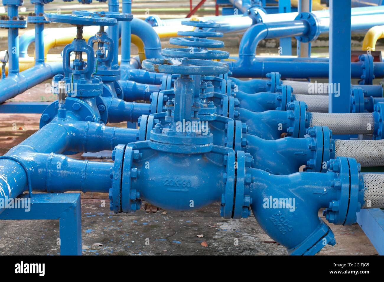
Keeping the flow of oil and gas in pipelines is a monumental task and requires several reliable pieces of equipment. Gas valves are one of these crucial components. Without gas valves, the oil and gas industry could not ensure that crude oil, refined gas, natural gas, and other materials get to their destination. Learn the basics of valves, including seven common types used within the oil and gas industry, to better understand what is required for the smooth and safe flow of materials.
A gas valve is a device used to regulate the flow of oil and gas. Opening or closing an aperture controls the amount of liquids and gases allowed through pipes. The valve controls the flow of fluids by stopping and starting, adjusting the amounts, controlling the direction, regulating pressure, or relieving pressure.
No two environments are the same. Some are highly corrosive. At the same time, others function under constant high pressure. Because of these variants, many different types of valves have been developed over the decades. Each type of valve has its own advantages and disadvantages. Successful operation and application require understanding the different types and uses within the gas and oil industry.
There are several types of gas valves because of the different environments in which they are used. Below is a breakdown of seven kinds commonly used in the oil and gas industry.
The gate valve may be the most commonly used in the industry. It uses a gate system to open or close a pipeline entirely. This is an excellent choice if the flow rate needs to be controlled and maintained. When the actuator completely opens the valve, the channel is unobstructed, allowing even slurry fluids like crude oil to flow easier. While it is not an ideal candidate if throttling is required in an application, there is not a noticeable pressure drop when this valve is used.
When pressure control is necessary, the globe valve is frequently chosen. It is also often used for open and close operations. The valve plug sits vertically raised and lowered by the actuator as needed. They tend to create a more significant pressure drop than other valve types because of the S-shaped passageway within them. They are a good choice for flow regulation and throttling functions.
Gas refineries find check valves extremely helpful as the device opens under pressure and does not allow backflow of fluid or material. Because of the restricted backflow, cross-contamination of the product is prevented. That is, different materials can use the same pipeline. There is no need for an actuator as required in other valve types. However, it does need precise installation to ensure the response to fluid pressure occurs as required.
The plug valve comprises a plug-shaped disc with a horizontal passageway bored through it. When the linear valve is open, fluid will move through the hole. Turning the actuator 90 degrees from the open position blocks any flow through the pipeline. This valve is not suggested for throttling functions but is ideal for unrefined oil products as found in biogas production.
Ball valves are rotary valves that give pipelines fast shut-offs where tight sealing is often required. They are best suited for operation under fully open or fully closed positions as they do not offer reasonable regulation control or throttle functions. This type of valve comes in many different styles, which provides options within the industry. For example, a floating ball valve works better in low-to-medium pressure pipelines, and trunnion ball valves can handle high-pressure conditions. These are easy to repair, offer solid sealing, and provide quick shut-offs.
These valves are simple in their construction, are lightweight, and compact. They use a disc-type element held by a rod to regulate flow. They can handle high-pressure pipelines and allow easy flow of materials. When they are closed, they shut tightly. Often, these are used in pipes with large diameters and where a gate valve is not applicable.
These valves provide additional safety of equipment either upstream or downstream from them. This type of valve may be found immediately before a regulator and is designed to remain open until a significant pressure change is detected. It then immediately shuts off the flow and must be reopened manually. They are sometimes referred to as relief and safety valves and are vital to the oil and gas industry in avoiding accidents and injury.
Because gas valves come in many different types and provide various functionalities, choosing the best one may be challenging. It is helpful to consider the primary function under which it will be used. Does the environment involve much pressure? Is there a need for additional safety measures provided by a slam-shut valve? Can the actuator be automated, or does it require only manual movement?
Additionally, consider the type of environment where the valve will need to function. By asking questions and taking the working environment into account, it is feasible to determine the best valve for the process at hand. The answers will indicate the type of materials best suited for the function.
For more than 30 years, Norgas Controls has provided the Canadian gas industry with quality valves, including slam-shut valves, gas shut-off ball valves, and gas plug valves. Contact us anytime for more information about our gas valves or any other product we carry. Our team is friendly and knowledgeable, standing ready to answer your questions and help obtain the best equipment for your project.

Dual gas safety valve assembly. The gas oven safety valve works with the oven igniter to provide gas to the burner. If the safety valve fails, the oven won’t heat. Since safety valves rarely fail, be sure to check more commonly defective parts before replacing the safety valve.

Natural gas is an abundant fuel that is used for both industrial and residential energy and is one of the few energy sources that is delivered directly into our homes. Because it’s also a flammable, potentially explosive fluid, utilities and distribution companies are required to prioritize safety and devote focus to their protection systems to prevent accidents.
As we have seen in recent events, even with that knowledge and safety precautions in place, it is still possible for something to potentially go wrong.
Every natural gas system is designed and approved for a maximum allowable operating pressure (MAOP). Pressure regulation or control devices are used to keep the system pressure under that maximum rating. In residential supply systems, the MAOP can be extremely low; often only a few inches of water column (<1 PSI).
Natural gas supply systems vary in design and pressures, and it’s up to the utility or operator to select the appropriate safety devices for their system, in line with Federal regulations, codes, and company design standards. The following provides a basic overview of today’s common methods to achieve over-pressure protection.
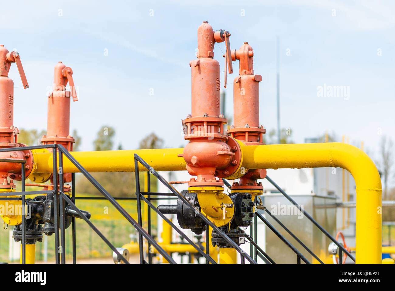
In years gone by, pressure relief valves (PRV) were the most common overpressure protection method for gas pipelines. As relief valves sensed downstream pressure exceeded the setpoint, they automatically opened to relieve the excess pressure. While this method is proven, it also comes with some disadvantages.
More than one relief valve may be required to ensure sufficient capacity for all conditions, with each valve set at a slightly different set pressure such that they activate in sequence depending on the level of overpressure in the system. This pressure build-up with this design must be considered in determining safe operating and relieving pressures.
When relieving, these valves are not only loud, but they also vent flammable, unfriendly greenhouse gas emissions (90-95% methane) direct into our atmosphere.
Relief valves used in these systems can be relieving regulators (back-pressure regulators), either spring-loaded or pilot operated, a control valve, generally for larger capacity systems.
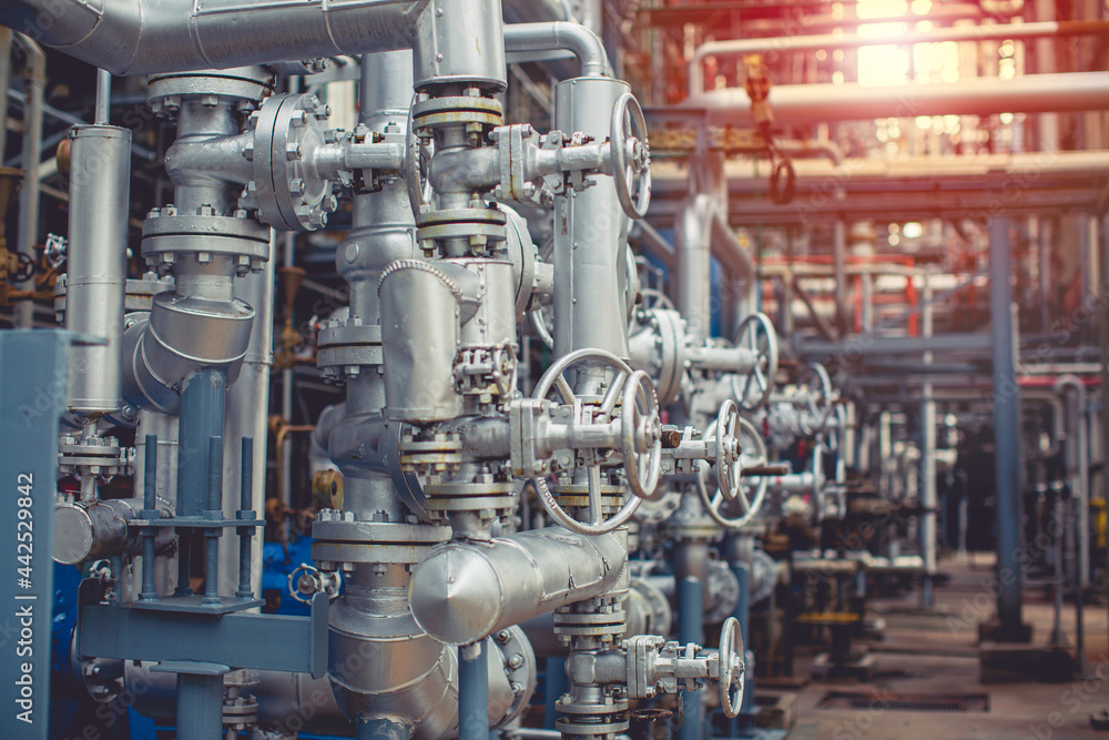
The most common system used today for natural gas regulation stations is two pilot operated regulators, or control valves, in series with one operating as the “worker” and the other set with a slightly higher set pressure as the “monitor.” This results in the Worker being the primary controlling device that is functioning under normal conditions. The monitor will remain open unless it senses the downstream pressure has increased beyond its higher set pressure at which time it will start to close and control the pressure at its higher setting. This creates a redundant system that statistically reduces the risk of total failure by 400%.
This system can be constructed using control valves or pilot operated regulators. Pilot regulators are usually simpler designs and have no external bleeds (no venting to environment) when operating and are often preferred when capacity requirements allow. Pilot operated designs are preferred over spring loaded versions as they are more sensitive, which higher accuracy – typically within 1% as opposed to 15% for spring return designs.
Control valves are preferred for use as worker/monitors and become necessary in high volume or high pressure drop systems. The control valve used is often a rotary ball type valve due to its high inherent capacity and low restriction when wide open.
Since control valves are not self-operated, a pressure sensing device is required to provide feedback of regulated pressure, and a controller is necessary to vary the valve position in response to that pressure. Industrial applications, where instrument air or power sources are available, those devices are typically pneumatic or electrically operated. But those resources are not always available in remote locations where gas regulation may be required, thus another, simpler option should be considered.
Using the higher pressure natural gas from the upstream side of the system, Valve Regulating Pilots can power a control valve directly without any external power supply, essentially combining the pressure sensor/transmitter and controller in one device. There are extremely low-bleed versions as well as designs that vent back into the pipeline, eliminating any atmospheric venting. These devices can transform a control valve into a self-operated regulator while maintaining the high capacity and pressure drop capability of the heavy-duty valve. (Figure 2 & 3)
The Slam Shut Valve can also be equipped for under-pressure protection and provides an additional layer of over-pressure protection in the event pressure regulation is lost. The difference is with the other methods above gas continues to flow with the additional devices working to regulate it. But if something goes wrong with those secondary devices, then what? Although not desirable as a first protection method, if the regulating devices, both primary and secondary fail, a slam-shut system will isolate the gas flow.
Slam Shut valves can be standalone devices or as an integral part of a pilot operated regulator, each option designed with their own sensing and control mechanisms.
Its function is simple, upon sensing a pressure exceeding setpoint, for over pressure protection, or below setpoint for under pressure, the internal mechanism is unlatched and the isolation flapper closes. The flapper remains in that position, stopping all gas flow, until it is manually reset. This provides system protection and keeps the system shut down until the cause of failure is identified and corrected. (Figure 5)
An added benefit of the slam shut system is the dual security provided in the case of under-pressure protection. Gas appliances are designed to operate with a certain gas supply pressure. What happens if the pressure is less than that? We see pilot lights in older home furnaces, water heaters, stoves, fireplaces, etc.
If the gas pressure drops too low to maintain that pilot light, the gas may not be ignited when delivered. If that occurred, gas could build up in the local atmosphere and in a worst-case scenario, that gas build-up could ignite resulting in an explosion. For this reason, under-pressure protection, that would shut off all gas flow if the pressure drops below a safe point, is also an important consideration in system design.
Overall natural gas system safety is a priority for everyone involved. Gas systems can be very complex, and each system must be assessed to determine the most appropriate regulation and safety system to employ. The purpose of this article is to provide an overview of several methods and equipment that can be used to help ensure safe gas regulation and delivery. P&GJ
Author: John Deveau is senior product manager for Becker and Mooney brand of gas control and regulator product lines at Baker Hughes, a GE Company. He has 35 years of experience in the control valve and regulator industry.


 8613371530291