
fire safety valve for oxygen price

All DirectHomeMedical offers online support through our website, live chat and toll free support during normal business hours, and email support 24-hours a day. Please contact us if you have any questions about our services or the products we sell. DirectHomeMedical.com is authorized and approved, by the manufacturers we represent, to sell and ship products to end-users residing in the United States, not to other third parties or businesses. A prescription is required for the purchase of certain products on this site. All products offered are sourced directly from the original equipment manufacturers or their representatives. PROPOSITION 65 WARNING: Some products on this site may contain a chemical known to the State of California to cause cancer, birth defects or other reproductive harm. COPYRIGHTS: Selected product images and descriptions used throughout this site are used with the permission of the copyright holders. All ResMed Product Images © ResMed. All Philips Respironics Product Images © Philips Respironics. All Fisher & Paykel Healthcare Product Images © Fisher & Paykel Healthcare. Site Design & Content Copyright © 2004-2018 DirectHomeMedical. Respironics recommends that new patients purchase their devices, masks and initial accessories from a homecare company that can provide an individualized patient equipment set-up, clinical and after-sale support, and a program to assist patients with therapy success. All products and services advertised on this site are provided by DirectHomeMedical.com or its designates. DirectHomeMedical occasionally offers discounts via coupon code. Coupon codes cannot be combined and there is a limit of one coupon per order. DISCLAIMER: Information on this website is informational only and should not replace the advice of a physician.

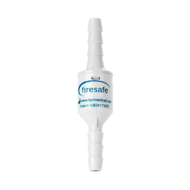
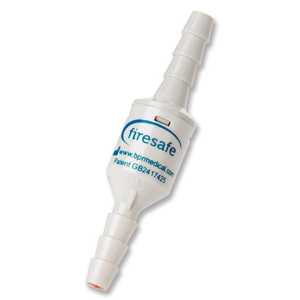
The Firesafe Cannula Valve and Nozzle are designed to automatically stop the flow of oxygen in the event that the downstream oxygen tubing is ignited. These offer a cost-effective solution to lower the risk of serious patient injury in an oxygen fire. The valve and nozzle can be installed in seconds and helps keep patients safe no matter what method of oxygen delivery they use. With a 4 year intended life (or until it shuts off in the event of a fire), they serve as a longer-lasting tubing connector.

The Firesafe™ MKII Cannula Valve acts like a thermal fuse protecting both patient and oxygen source from propagating fire. To prevent incorrect installation, the valve is bi-directional, allowing it to be fitted in either direction.
This website uses cookies to improve your experience while you navigate through the website. Out of these, the cookies that are categorized as necessary are stored on your browser as they are essential for the working of basic functionalities of the website. We also use third-party cookies that help us analyze and understand how you use this website. These cookies will be stored in your browser only with your consent. You also have the option to opt-out of these cookies. But opting out of some of these cookies may affect your browsing experience.
Searching for tools to control the flow of your piping system? Explore one of the largest featured collections of products and discover a range of wholesale oxygen safety valve on Alibaba.com. When you search for oxygen safety valve and related items, you will be able to find many types of oxygen safety valve varying in size, shape, use, and quality, all at prices in which are highly reasonable!
There are many uses of valves - mainly controlling the flow of fluids and pressure. Some examples include regulating water for irrigation, industrial uses for controlling processes, and residential piping systems. Magnetic valves like those using the solenoid, are often used in a range of industrial processes. Whereas backflow preventers are often used in residential and commercial buildings to ensure the safety and hygiene of the water supplies. Whether you are designing a regulation system for irrigation or merely looking for a new replacement, you will be able to find whatever type of oxygen safety valve that you need. Our products vary from check valves to pressure reducing valves, ball valves, butterfly valves, thermostatic mixing valves, and a lot more.

Select from a variety of wholesale oxygen cylinder safety valve for the appropriate type of equipment that you need. There are several popular oxygen c oxygen safety valve on sale at great prices. Some examples include the solenoid valve, water pressure regulator, actuator valve, globe valve, and sprinkler valve. These instruments can be used to control the flow of substances in the liquid and gaseous states. Whether you are a scientist, plumber, or store supplier, you will likely be able to find the right tools for the job.
There are many uses of valves - mainly controlling the flow of fluids and pressure. Some examples include regulating water for irrigation, industrial uses for controlling processes, and residential piping systems. Magnetic valves like those using the solenoid, are often used in a range of industrial processes. Whereas backflow preventers are often used in residential and commercial buildings to ensure the safety and hygiene of the water supplies. Whether you are designing a regulation system for irrigation or merely looking for a new replacement, you will be able to find whatever type of oxygen cylinder safety valve that you need. Our products vary from check valves to pressure reducing valves, ball valves, butterfly valves, thermostatic mixing valves, and a lot more.
Alibaba.com features a comprehensive range of high-quality, efficient, and durable oxygen cylinder safety valve for distinct types of commercial and personal uses. Available in multiple variations and models, these products are ideal for all kinds of machinery and vehicle engines for optimal performance. The oxygen cylinder safety valve varieties you can find on the site are made of sturdy materials that contribute to the long-lasting lifespan of the products and are unparalleled when it comes to offering flawless, consistent fuel flow to the engines. Grab these unique and robust oxygen cylinder safety valve from the top brands and manufacturers in the industry for mind-blowing prices.Whether you are looking for perfect oxygen cylinder safety valve to fit into your vehicle engine for smoother and consistent fuel flow or if you are looking for sturdy valves to fit into an irrigation system, heavy-duty machines, you can find.

This website is using a security service to protect itself from online attacks. The action you just performed triggered the security solution. There are several actions that could trigger this block including submitting a certain word or phrase, a SQL command or malformed data.

This website is using a security service to protect itself from online attacks. The action you just performed triggered the security solution. There are several actions that could trigger this block including submitting a certain word or phrase, a SQL command or malformed data.

In order for a fire to occur, all three legs of what’s called the “fire triangle” must be present: an ignition source, fuel and oxygen. In most cases, it is practically impossible to completely remove these three components from a system — especially within oxygen systems containing many flammable substances that can act as ignition sources, such as contaminant particles, seal materials, lubricants and compressed gas.
However, you can incorporate protective components made from non-flammable materials, such as OXYCHECK valves. With its many essential safety features, this oxygen filter component provides an extra element of security for commercial and industrial users. At Chase Filters and Components, we have the OXYCHECK components that will bring the highest value and protection to your oxygen systems.
OXYCHECK oxygen system components are completely non-flammable in oxygen at pressures equal to or higher than peak permissible working pressures. These oxygen filter elements eliminate the fuel leg of the fire triangle, reducing the risk of fires as well as ignition consequences. The extensive and meticulous engineering process behind OXYCHECK valves supplies oxygen components with the utmost level of protection.
Additionally, OXYCHECK elements promote exceptional fire safety in pressurized and concentrated oxygen. These valves exhibit high-performance rates in corrosive, extreme and oxidizing environments, so you can be sure your systems are safe no matter the conditions.
When you purchase OXYCHECK products from Chase Filters and Components, you’ll receive a state-of-the-art valve designed with the ideal characteristics for fire suppression. With durable and fire-resistant elements and high-performance rates, OXYCHECK’s oxygen filter components rank above the rest.
OXYCHECK systems serve in a broad array of industries and applications. With high safety ratings and performance rates, these highly sought-after components ensure security and protection from fires in a wide range of commercial settings.
Safety is of optimal importance when it comes to aviation. OXYCHECK valves ensure that all passengers, crew and valuable aircraft assets are safe and out of harm’s way. These components are suitable for use in extreme temperatures and under dynamic conditions, making them excellent for a wide array of aviation applications, such as:
OXYCHECK elements are popular in the medical field due to their strict cleanliness standards and lack of fluorinated materials. Affordable and safe, our oxygen filter components are useful in many life support applications, including:
For oxygen filter elements of the highest safety standards, choose Chase Filters and Components. With over a decade of experience in high-pressure filtration systems including those for air, water, hydraulic fluid, gas and more, we have all of the filter options you need to get the job done. With an emphasis on quality and safety, our team of experienced design engineers is ready to assist you.

An increased risk of fire is an unfortunate and all too common problem associated with oxygen therapy. Firesafe™ devices help reduce this risk by isolating the oxygen flow and extinguishing a fire tracking back along the oxygen delivery tubing.
Firesafe™ devices can be installed directly in the oxygen delivery circuit and at the interface with the oxygen supply equipment, providing the following benefits:
Flammable mixture. Mixtures of fuel gases and air or oxygen may be explosive and shall be guarded against. No device or attachment facilitating or permitting mixtures of air or oxygen with flammable gases prior to consumption, except at the burner or in a standard torch, shall be allowed unless approved for the purpose.
Maximum pressure. Under no condition shall acetylene be generated, piped (except in approved cylinder manifolds) or utilized at a pressure in excess of 15 psig (103 kPa gauge pressure) or 30 psia (206 kPa absolute). The 30 psia (206 kPa absolute) limit is intended to prevent unsafe use of acetylene in pressurized chambers such as caissons, underground excavations or tunnel construction.) This requirement is not intended to apply to storage of acetylene dissolved in a suitable solvent in cylinders manufactured and maintained according to U.S. Department of Transportation requirements, or to acetylene for chemical use. The use of liquid acetylene shall be prohibited.
Personnel. Workmen in charge of the oxygen or fuel-gas supply equipment, including generators, and oxygen or fuel-gas distribution piping systems shall be instructed and judged competent by their employers for this important work before being left in charge. Rules and instructions covering the operation and maintenance of oxygen or fuel-gas supply equipment including generators, and oxygen or fuel-gas distribution piping systems shall be readily available.
All portable cylinders used for the storage and shipment of compressed gases shall be constructed and maintained in accordance with the regulations of the U.S. Department of Transportation, 49 CFR parts 171-179.
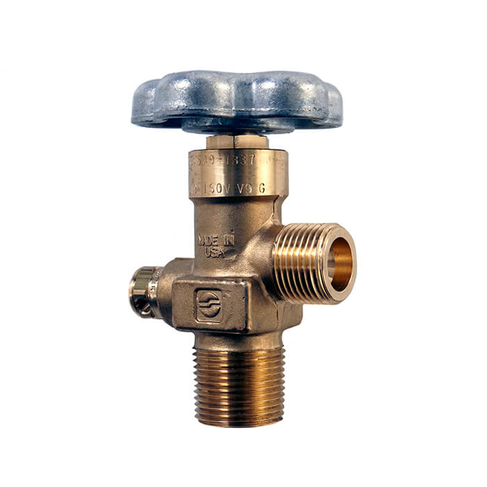
Compressed gas cylinders shall be legibly marked, for the purpose of identifying the gas content, with either the chemical or the trade name of the gas. Such marking shall be by means of stenciling, stamping, or labeling, and shall not be readily removable. Whenever practical, the marking shall be located on the shoulder of the cylinder.
Compressed gas cylinders shall be equipped with connections complying with the American National Standard Compressed Gas Cylinder Valve Outlet and Inlet Connections, ANSI B57.1—1965, which is incorporated by reference as specified in §1910.6.
All cylinders with a water weight capacity of over 30 pounds (13.6 kg) shall be equipped with means of connecting a valve protection cap or with a collar or recess to protect the valve.
Valve protection caps, where cylinder is designed to accept a cap, shall always be in place, hand-tight, except when cylinders are in use or connected for use.
Fuel-gas cylinder storage. Inside a building, cylinders, except those in actual use or attached ready for use, shall be limited to a total gas capacity of 2,000 cubic feet (56 m3) or 300 pounds (135.9 kg) of liquefied petroleum gas.
For storage in excess of 2,000 cubic feet (56 m3) total gas capacity of cylinders or 300 (135.9 kg) pounds of liquefied petroleum gas, a separate room or compartment conforming to the requirements specified in paragraphs (f)(6)(i)(H) and (f)(6)(i)(I) of this section shall be provided, or cylinders shall be kept outside or in a special building. Special buildings, rooms or compartments shall have no open flame for heating or lighting and shall be well ventilated. They may also be used for storage of calcium carbide in quantities not to exceed 600 (271.8 kg) pounds, when contained in metal containers complying with paragraphs (g)(1)(i) and (g)(1)(ii) of this section.
Oxygen cylinders shall not be stored near highly combustible material, especially oil and grease; or near reserve stocks of carbide and acetylene or other fuel-gas cylinders, or near any other substance likely to cause or accelerate fire; or in an acetylene generator compartment.
Oxygen cylinders stored in outside generator houses shall be separated from the generator or carbide storage rooms by a noncombustible partition having a fire-resistance rating of at least 1 hour. This partition shall be without openings and shall be gastight.
Oxygen cylinders in storage shall be separated from fuel-gas cylinders or combustible materials (especially oil or grease), a minimum distance of 20 feet (6.1 m) or by a noncombustible barrier at least 5 feet (1.5 m) high having a fire-resistance rating of at least one-half hour.
Where a liquid oxygen system is to be used to supply gaseous oxygen for welding or cutting and the system has a storage capacity of more than 13,000 cubic feet (364 m3) of oxygen (measured at 14.7 psia (101 kPa) and 70 °F (21.1 °C)), connected in service or ready for service, or more than 25,000 cubic feet (700 m3) of oxygen (measured at 14.7 psia (101 kPa) and 70 °F (21.1 °C)), including unconnected reserves on hand at the site, it shall comply with the provisions of the Standard for Bulk Oxygen Systems at Consumer Sites, NFPA No. 566—1965, which is incorporated by reference as specified in §1910.6.
Cylinders, cylinder valves, couplings, regulators, hose, and apparatus shall be kept free from oily or greasy substances. Oxygen cylinders or apparatus shall not be handled with oily hands or gloves. A jet of oxygen must never be permitted to strike an oily surface, greasy clothes, or enter a fuel oil or other storage tank.
When transporting cylinders by a crane or derrick, a cradle, boat, or suitable platform shall be used. Slings or electric magnets shall not be used for this purpose. Valve-protection caps, where cylinder is designed to accept a cap, shall always be in place.
Valve-protection caps shall not be used for lifting cylinders from one vertical position to another. Bars shall not be used under valves or valve-protection caps to pry cylinders loose when frozen to the ground or otherwise fixed; the use of warm (not boiling) water is recommended. Valve-protection caps are designed to protect cylinder valves from damage.
Unless cylinders are secured on a special truck, regulators shall be removed and valve-protection caps, when provided for, shall be put in place before cylinders are moved.
Cylinders not having fixed hand wheels shall have keys, handles, or nonadjustable wrenches on valve stems while these cylinders are in service. In multiple cylinder installations only one key or handle is required for each manifold.
Cylinders shall be kept far enough away from the actual welding or cutting operation so that sparks, hot slag, or flame will not reach them, or fire-resistant shields shall be provided.
Cylinders shall not be placed where they might become part of an electric circuit. Contacts with third rails, trolley wires, etc., shall be avoided. Cylinders shall be kept away from radiators, piping systems, layout tables, etc., that may be used for grounding electric circuits such as for arc welding machines. Any practice such as the tapping of an electrode against a cylinder to strike an arc shall be prohibited.
Unless connected to a manifold, oxygen from a cylinder shall not be used without first attaching an oxygen regulator to the cylinder valve. Before connecting the regulator to the cylinder valve, the valve shall be opened slightly for an instant and then closed. Always stand to one side of the outlet when opening the cylinder valve.
Cylinder valves shall not be tampered with nor should any attempt be made to repair them. If trouble is experienced, the supplier should be sent a report promptly indicating the character of the trouble and the cylinder"s serial number. Supplier"s instructions as to its disposition shall be followed.
Before connecting a regulator to a cylinder valve, the valve shall be opened slightly and closed immediately. The valve shall be opened while standing to one side of the outlet; never in front of it. Never crack a fuel-gas cylinder valve near other welding work or near sparks, flame, or other possible sources of ignition.
Nothing shall be placed on top of an acetylene cylinder when in use which may damage the safety device or interfere with the quick closing of the valve.
If cylinders are found to have leaky valves or fittings which cannot be stopped by closing of the valve, the cylinders shall be taken outdoors away from sources of ignition and slowly emptied.
A warning should be placed near cylinders having leaking fuse plugs or other leaking safety devices not to approach them with a lighted cigarette or other source of ignition. Such cylinders should be plainly tagged; the supplier should be promptly notified and his instructions followed as to their return.
Fuel-gas shall never be used from cylinders through torches or other devices equipped with shutoff valves without reducing the pressure through a suitable regulator attached to the cylinder valve or manifold.
Where a special wrench is required it shall be left in position on the stem of the valve while the cylinder is in use so that the fuel-gas flow can be quickly turned off in case of emergency. In the case of manifolded or coupled cylinders at least one such wrench shall always be available for immediate use.
Except as provided in paragraph (c)(1)(iii) of this section fuel-gas cylinders connected to one manifold inside a building shall be limited to a total capacity not exceeding 300 pounds (135.9 kg) of liquefied petroleum gas or 3,000 cubic feet (84 m3) of other fuel-gas. More than one such manifold with connected cylinders may be located in the same room provided the manifolds are at least 50 feet (15 m) apart or separated by a noncombustible barrier at least 5 feet (1.5 m) high having a fire-resistance rating of at least one-half hour.
Separate manifold buildings or rooms may also be used for the storage of drums of calcium carbide and cylinders containing fuel gases as provided in paragraph (b)(3) of this section. Such buildings or rooms shall have no open flames for heating or lighting and shall be well-ventilated.
Oxygen manifolds shall not be located in an acetylene generator room. Oxygen manifolds shall be separated from fuel-gas cylinders or combustible materials (especially oil or grease), a minimum distance of 20 feet (6.1 m) or by a noncombustible barrier at least 5 feet (1.5 m) high having a fire-resistance rating of at least one-half hour.
Except as provided in paragraph (c)(2)(iv) of this section, oxygen cylinders connected to one manifold shall be limited to a total gas capacity of 6,000 cubic feet (168 m3). More than one such manifold with connected cylinders may be located in the same room provided the manifolds are at least 50 feet (15 m) apart or separated by a noncombustible barrier at least 5 feet (1.5 m) high having a fire-resistance rating of at least one-half hour.
An oxygen manifold, to which cylinders having an aggregate capacity of more than 6,000 cubic feet (168 m3) of oxygen are connected, should be located outdoors or in a separate noncombustible building. Such a manifold, if located inside a building having other occupancy, shall be located in a separate room of noncombustible construction having a fire-resistance rating of at least one-half hour or in an area with no combustible material within 20 feet (6.1 m) of the manifold.
An oxygen manifold or oxygen bulk supply system which has storage capacity of more than 13,000 cubic feet (364 m3) of oxygen (measured at 14.7 psia (101 kPa) and 70 °F (21.1 °C)), connected in service or ready for service, or more than 25,000 cubic feet (700 m3) of oxygen (measured at 14.7 psia (101 kPa) and 70 °F (21.1 °C)), including unconnected reserves on hand at the site, shall comply with the provisions of the Standard for Bulk Oxygen Systems at Consumer Sites, NFPA No. 566-1965.
Manifolds shall be of substantial construction suitable for use with oxygen at a pressure of 250 psig (1.7 MPa). They shall have a minimum bursting pressure of 1,000 psig (6.8 MPa) and shall be protected by a safety relief device which will relieve at a maximum pressure of 500 psig (3.4 MPa). DOT-4L200 cylinders have safety devices which relieve at a maximum pressure of 250 psig (1.7 MPa) (or 235 psig (1.6 MPa) if vacuum insulation is used).
The assembled manifold including leads shall be tested and proven gas-tight at a pressure of 300 psig (2.04 MPa). The fluid used for testing oxygen manifolds shall be oil-free and not combustible.
Portable outlet headers shall not be used indoors except for temporary service where the conditions preclude a direct supply from outlets located on the service piping system.
Each outlet on the service piping from which oxygen or fuel-gas is withdrawn to supply a portable outlet header shall be equipped with a readily accessible shutoff valve.
Portable outlet headers for fuel-gas service shall be provided with an approved hydraulic back-pressure valve installed at the inlet and preceding the service outlets, unless an approved pressure-reducing regulator, an approved back-flow check valve, or an approved hydraulic back-pressure valve is installed at each outlet. Outlets provided on headers for oxygen service may be fitted for use with pressure-reducing regulators or for direct hose connection.
Each service outlet on portable outlet headers shall be provided with a valve assembly that includes a detachable outlet seal cap, chained or otherwise attached to the body of the valve.
When acetylene cylinders are coupled, approved flash arresters shall be installed between each cylinder and the coupler block. For outdoor use only, and when the number of cylinders coupled does not exceed three, one flash arrester installed between the coupler block and regulator is acceptable.
Piping and fittings shall comply with section 2, Industrial Gas and Air Piping Systems, of the American National Standard Code for Pressure Piping ANSI B31.1, 1967, which is incorporated by reference as specified in §1910.6, insofar as it does not conflict with paragraphs (d)(1)(i)(A)(1) and (d)(1)(i)(A)(2) of this section:
Copper tubing shall be Types K or L in accordance with the Standard Specification for Seamless Copper Water Tube, ASTM B88-66a, which is incorporated by reference as specified in §1910.6.
When oxygen is supplied to a service piping system from a low-pressure oxygen manifold without an intervening pressure regulating device, the piping system shall have a minimum design pressure of 250 psig (1.7 MPa). A pressure regulating device shall be used at each station outlet when the connected equipment is for use at pressures less than 250 psig (1.7 MPa).
Joints in steel or wrought iron piping shall be welded, threaded or flanged. Fittings, such as ells, tees, couplings, and unions, may be rolled, forged or cast steel, malleable iron or nodular iron. Gray or white cast iron fittings are prohibited.
All piping shall be run as directly as practicable, protected against physical damage, proper allowance being made for expansion and contraction, jarring and vibration. Pipe laid underground in earth shall be located below the frost line and protected against corrosion. After assembly, piping shall be thoroughly blown out with air, nitrogen, or carbon dioxide to remove foreign materials. For oxygen piping, only oil-free air, oil-free nitrogen, or oil-free carbon dioxide shall be used.
Only piping which has been welded or brazed shall be installed in tunnels, trenches or ducts. Shutoff valves shall be located outside such conduits. Oxygen piping may be placed in the same tunnel, trench or duct with fuel-gas pipelines, provided there is good natural or forced ventilation.
Low points in piping carrying moist gas shall be drained into drip pots constructed so as to permit pumping or draining out the condensate at necessary intervals. Drain valves shall be installed for this purpose having outlets normally closed with screw caps or plugs. No open end valves or petcocks shall be used, except that in drips located out of doors, underground, and not readily accessible, valves may be used at such points if they are equipped with means to secure them in the closed position. Pipes leading to the surface of the ground shall be cased or jacketed where necessary to prevent loosening or breaking.
Gas cocks or valves shall be provided for all buildings at points where they will be readily accessible for shutting off the gas supply to these buildings in any emergency. There shall also be provided a shutoff valve in the discharge line from the generator, gas holder, manifold or other source of supply.
Fittings and lengths of pipe shall be examined internally before assembly and, if necessary freed from scale or dirt. Oxygen piping and fittings shall be washed out with a suitable solution which will effectively remove grease and dirt but will not react with oxygen. Hot water solutions of caustic soda or trisodium phosphate are effective cleaning agents for this purpose.
Piping shall be thoroughly blown out after assembly to remove foreign materials. For oxygen piping, oil-free air, oil-free nitrogen, or oil-free carbon dioxide shall be used. For other piping, air or inert gas may be used.
No welding or cutting shall be performed on an acetylene or oxygen pipeline, including the attachment of hangers or supports, until the line has been purged. Only oil-free air, oil-free nitrogen, or oil-free carbon dioxide shall be used to purge oxygen lines.
Underground pipe and tubing and outdoor ferrous pipe and tubing shall be covered or painted with a suitable material for protection against corrosion.
Aboveground piping systems shall be marked in accordance with the American National Standard Scheme for the Identification of Piping Systems, ANSI A13.1−1956, which is incorporated by reference as specified in §1910.6.
Piping systems shall be tested and proved gastight at 1½ times the maximum operating pressure, and shall be thoroughly purged of air before being placed in service. The material used for testing oxygen lines shall be oil free and noncombustible. Flames shall not be used to detect leaks.
The fuel-gas and oxygen piping systems, including portable outlet headers shall incorporate the protective equipment shown in Figures Q-1, Q-2, and Q-3. When only a portion of a fuel-gas system is to be used with oxygen, only that portion need comply with this paragraph (e)(3)(i).
Legend: PF--Protective equipment in fuel gas piping. VF--Fuel gas station outlet valve. VO Oxygen station outlet valve. SF--Backflow prevention device(s) at fuel gas station outlet. SO--Backflow prevention device(s) at oxygen station outlet.
Excessive back pressure of oxygen in the fuel-gas supply system. The three functions of the protective equipment may be combined in one device or may be provided by separate devices.
Backflow protection shall be provided by an approved device that will prevent oxygen from flowing into the fuel-gas system or fuel from flowing into the oxygen system (see SF, Figures Q-1 and Q-2).
A check valve, pressure regulator, hydraulic seal, or combination of these devices shall be provided at each station outlet, including those on portable headers, to prevent backflow, as shown in Figures Q-1, Q-2, and Q-3 and designated as SF and SO.
When approved pipeline protective equipment (designated PF) is located at the station outlet as in Figure Q-3, no additional check valve, pressure regulator, or hydraulic seal is required.
A shutoff valve (designated VF and VO) shall be installed at each station outlet and shall be located on the upstream side of other station outlet equipment.
Where station outlets are equipped with approved backflow and flashback protective devices, as many as four torches may be supplied from one station outlet through rigid piping, provided each outlet from such piping is equipped with a shutoff valve and provided the fuel-gas capacity of any one torch does not exceed 15 cubic feet (0.42 m3) per hour. This paragraph (e)(4)(viii) does not apply to machines.
Hose for oxy-fuel gas service shall comply with the Specification for Rubber Welding Hose, 1958, Compressed Gas Association and Rubber Manufacturers Association, which is incorporated by reference as specified in §1910.6.
When parallel lengths of oxygen and acetylene hose are taped together for convenience and to prevent tangling, not more than 4 inches (10.2 cm) out of 12 inches (30.5 cm) shall be covered by tape.
Hose connections shall be clamped or otherwise securely fastened in a manner that will withstand, without leakage, twice the pressure to which they are normally subjected in service, but in no case less than a pressure of 300 psi (2.04 MPa). Oil-free air or an oil-free inert gas shall be used for the test.
Pressure-reducing regulators shall be used only for the gas and pressures for which they are intended. The regulator inlet connections shall comply with Regulator Connection Standards, 1958, Compressed Gas Association.
When regulators or parts of regulators, including gages, need repair, the work shall be performed by skilled mechanics who have been properly instructed.
Union nuts and connections on regulators shall be inspected before use to detect faulty seats which may cause leakage of gas when the regulators are attached to the cylinder valves.
Generators shall be of approved construction and shall be plainly marked with the maximum rate of acetylene in cubic feet per hour for which they are designed; the weight and size of carbide necessary for a single charge; the manufacturer"s name and address; and the name or number of the type of generator.
The total hourly output of a generator shall not exceed the rate for which it is approved and marked. Unless specifically approved for higher ratings, carbide-feed generators shall be rated at 1 cubic foot (0.028 m3) per hour per pound of carbide required for a single complete charge.
Relief valves shall be regularly operated to insure proper functioning. Relief valves for generating chambers shall be set to open at a pressure not in excess of 15 psig (103 kPa gauge pressure). Relief valves for hydraulic back pressure valves shall be set to open at a pressure not in excess of 20 psig (137 kPa gauge pressure).
Nonautomatic generators shall not be used for generating acetylene at pressures exceeding l psig (7 kPa gauge pressure), and all water overflows shall be visible.
Location. The space around the generator shall be ample for free, unobstructed operation and maintenance and shall permit ready adjustment and charging.
Generators shall be placed where water will not freeze. The use of common salt (sodium chloride) or other corrosive chemicals for protection against freezing is not permitted. (For heating systems see paragraph (f)(6)(iii) of this section.)
Water shall not be supplied through a continuous connection to the generator except when the generator is provided with an adequate open overflow or automatic water shutoff which will effectively prevent overfilling of the generator. Where a noncontinuous connection is used, the supply line shall terminate at a point not less than 2 inches (5 cm) above the regularly provided opening for filling so that the water can be observed as it enters the generator.
Unless otherwise specifically approved, generators shall not be fitted with continuous drain connections leading to sewers, but shall discharge through an open connection into a suitably vented outdoor receptacle or residue pit which may have such connections. An open connection for the sludge drawoff is desirable to enable the generator operator to observe leakage of generating water from the drain valve or sludge cock.
If acetylene is used from the gas holder without increase in pressure at some points but with increase in pressure by a compressor or booster pump at other points, approved piping protective devices shall be installed in each supply line. The low-pressure protective device shall be located between the gas holder and the shop piping, and the medium-pressure protective device shall be located between the compressor or booster pump and the shop piping (see Figure Q-4). Approved protective equipment (designated PF) is used to prevent: Backflow of oxygen into the fuel-gas supply system; passage of a flashback into the fuel-gas supply system; and excessive back pressure of oxygen in the fuel-gas supply system. The three functions of the protective equipment may be combined in one device or may be provided by separate devices.
Wiring and electric equipment in compressor or booster pump rooms or enclosures shall conform to the provisions of subpart S of this part for Class I, Division 2 locations.
Compressor or booster pumps shall be provided with pressure relief valves which will relieve pressure exceeding 15 psig (103 kPa gauge pressure) to a safe outdoor location as provided in paragraph (f)(4)(ii) of this section, or by returning the gas to the inlet side or to the gas supply source.
When a part of the generator house is to be used for the storage or manifolding of oxygen cylinders, the space to be so occupied shall be separated from the generator or carbide storage section by partition walls continuous from floor to roof or ceiling, of the type of construction stated in paragraph (f)(6)(i)(H) of this section. Such separation walls shall be without openings and shall be joined to the floor, other walls and ceiling or roof in a manner to effect a permanent gas-tight joint.
Explosion venting for outside generator houses and inside generator rooms shall be provided in exterior walls or roofs. The venting areas shall be equal to not less than 1 square foot (0.09 m2) per 50 cubic feet (1.4 m3) of room volume and may consist of any one or any combination of the following: Walls of light, noncombustible material preferably single-thickness, single-strength glass; lightly fastened hatch covers; lightly fastened swinging doors in exterior walls opening outward; lightly fastened walls or roof designed to relieve at a maximum pressure of 25 pounds per square foot (0.001 MPa).
The walls, partitions, floors, and ceilings of inside generator rooms shall be of noncombustible construction having a fire-resistance rating of at least 1 hour. The walls or partitions shall be continuous from floor to ceiling and shall be securely anchored. At least one wall of the room shall be an exterior wall.
Openings from an inside generator room to other parts of the building shall be protected by a swinging type, self-closing fire door for a Class B opening and having a rating of at least 1 hour. Windows in partitions shall be wired glass and approved metal frames with fixed sash. Installation shall be in accordance with the Standard for the Installation of Fire Doors and Windows, NFPA 80-1970, which is incorporated by reference as specified in §1910.6.
Heating shall be by steam, hot water, enclosed electrically heated elements or other indirect means. Heating by flames or fires shall be prohibited in outside generator houses or inside generator rooms, or in any enclosure communicating with them.
Generator houses or rooms shall have natural light during daylight hours. Where artificial lighting is necessary it shall be restricted to electric lamps installed in a fixed position. Unless specifically approved for use in atmospheres containing acetylene, such lamps shall be provided with enclosures of glass or other noncombustible material so designed and constructed as to prevent gas vapors from reaching the lamp or socket and to resist breakage. Rigid conduit with threaded connections shall be used.
Electric switches, telephones, and all other electrical apparatus which may cause a spark, unless specifically approved for use inside acetylene generator rooms, shall be located outside the generator house or in a room or space separated from the generator room by a gas-tight partition, except that where the generator system is designed so that no carbide fill opening or other part of the generator is open to the generator house or room during the operation of the generator, and so that residue is carried in closed piping from the residue discharge valve to a point outside the generator house or room, electrical equipment in the generator house or room shall conform to the provisions of subpart S of this part for Class I, Division 2 locations.
In the case of batch-type generators, when the charge of carbide is exhausted and before additional carbide is added, the generating chamber shall always be flushed out with water, renewing the water supply in accordance with the instruction card furnished by the manufacturer.
The carbide added each time the generator is recharged shall be sufficient to refill the space provided for carbide without ramming the charge. Steel or other ferrous tools shall not be used in distributing the charge.
Calcium carbide shall be contained in metal packages of sufficient strength to prevent rupture. The packages shall be provided with a screw top or equivalent. These packages shall be constructed water- and air-tight. Solder shall not be used in such a manner that the package would fail if exposed to fire.
Packages of calcium carbide, except for one of each size, shall be kept sealed. The seals shall not be broken when there is carbide in excess of 1 pound (0.5 kg) in any other unsealed package of the same size of carbide in the room.
In a separate room in a one-story building which may contain other occupancies, but without cellar or basement beneath the carbide storage section. Such rooms shall be constructed in accordance with paragraphs (f)(6)(i)(H) and (f)(6)(i)(I) of this section and ventilated in accordance with paragraph (f)(6)(ii) of this section. These rooms shall be used for no other purpose.
Calcium carbide in excess of 5,000 pounds (2,268 kg) shall be stored in one-story buildings without cellar or basement and used for no other purpose, or in outside generator houses. If the storage building is of noncombustible construction, it may adjoin other one-story buildings if separated therefrom by unpierced firewalls; if it is detached less than 10 feet (3 m) from such building or buildings, there shall be no opening in any of the mutually exposing sides of such buildings within 10 feet (3 m). If the storage building is of combustible construction, it shall be at least 20 feet (6.1 m) from any other one- or two-story building, and at least 30 feet (9.1 m) from any other building exceeding two stories.
Carbide containers to be stored outdoors shall be examined to make sure that they are in good condition. Periodic reexaminations shall be made for rusting or other damage to a container that might affect its water or air tightness.


 8613371530291