
safety valve for gas oven free sample

Most modern appliances have safety features built in, but your gas oven safety valve is arguably the most important. If an electrical appliance malfunctions, it can cause a fire, but a misfiring gas oven could potentially blow up your house. You don"t really need to know how the safety mechanism works to use your oven, but you may find that it gives you some extra peace of mind.
Broadly speaking, there are two ways a built-in safety mechanism can work. One option is that it remains "open" by default and to shut off if certain conditions are met. That"s how fuses and circuit breakers work in an electrical circuit: Ordinarily, the electricity is free to flow, but if the current grows too large, the fuse or breaker will blow and cut off the circulation of electricity.
The other option is for your safety mechanism to be "closed" by default and allow a device to operate only when the correct conditions are met. That"s how a gas oven safety valve works. Gas ordinarily is prevented from flowing, and if the valve is working correctly, it opens only when you want to light your oven.
Many gas stoves use what"s called a "hot surface igniter," a bar or element (similar to the ones on your stovetop) that gets hot enough to ignite the gas on contact. Gas oven safety valves on stoves with this type of ignition system take a couple of different approaches.
In one approach, a bimetallic strip operates the valve. It harnesses a simple scientific principle: Metals expand and contract at different rates when they"re heated and cooled. If you bond two suitable metals together in one strip, that strip will flex to a predictable degree as the temperature goes up and down. Wall-mount thermostats often use this principle, as do analog oven thermometers and the thermometer in the lid of your gas grill.
As appliance-repair website PartSelect explains, turning on your gas oven causes electricity to flow into the heating element of your hot surface igniter. As the igniter heats up, it warms a bimetallic strip inside your gas oven safety valve. When the igniter reaches its operating temperature, the bimetallic strip opens the valve and allows the gas to flow, igniting as it crosses the heated surface.
One intriguing thing about electricity is that a change in temperature can affect how well it passes through certain materials. For example, a lot of research revolves around superconductors – materials that offer very little resistance to an electrical current – but superconductors typically must be heavily chilled to work.
According to heating-equipment vendor Anglo Nordic, gas oven safety valves use a variation of that principle to operate. In these stoves, the flow of electrical current through the hot surface igniter becomes the control mechanism. The igniter"s bar is made of a material that offers less and less resistance to electricity as it heats. When it reaches the temperature required to ignite the gas, its resistance becomes low enough to trip the safety valve and open the flow of gas.
More modern ranges use an electrical igniter. When you turn on your oven, the gas begins flowing immediately, and it sends an electrical current to a piezo electric igniter. The current makes the igniter spark (like the manual igniter on your gas grill) and lights the oven"s burner. In this case, the safety valve works in the opposite way: An electronic sensor checks for the heat caused by ignition after a few seconds, and if it"s absent, it will close the valve and shut off the flow of gas.
It"s worth pointing out that not all gas ovens have a safety valve in the conventional sense. Older stoves simply use a pilot light, a small but constant flow of gas, which, in turn, feeds a small, candle-like flame. You essentially are the safety mechanism in this system: It"s up to you to check that the pilot is lit. When you turn on the gas manually, the small pilot flame ignites the main flame. It"s a mechanically simple system, which makes it durable, and for that reason, you"ll still see it used on commercial restaurant ranges, which must stand up to decades of heavy use.

Pilot ignition systems use a flame sensing element to sense whether the pilot is lit and the safety valve can open. The sensing element sits right in the pilot flame.
Just exactly where the sensor sits in the pilot flame is important. (See figure 6-A) If the sensing bulb is not in the right part of the flame, or if the pilot is adjusted too low or too high, it will not get hot enough and the safety valve will not open.
When two dissimilar metals (for example, copper and steel) are bonded together electrically, and then heated, they generate a tiny electrical current between them. The voltage is very small, measured in millivolts. This is the basis for a millivolt oven ignitor system. All that"s needed is a safety valve that will sense this tiny voltage and open the valve if it is present. If the pilot is out, there is no millivoltage and the safety valve will not open. See figure 6-B.
If the burner in a millivolt system will not start, typically the problem is the gas valve. Occasionally the problem might be the pilot generator or thermostat. The thermostat in these is just a temperature-sensitive on/off switch. To test, turn it on and test for continuity.
If that doesn"t work, we have a minor dilemma in determining whether the problem is the pilot generator or the safety valve. The dilemma here is that the voltages are too small to be measured with standard equipment. VOM millivolt adaptors cost nearly as much as the pilot generator itself. And the safety valve, which is usually the problem, costs twice as much as the pilot generator. So usually you just replace either or both of them. But don"t forget they are electrical parts, which are non-returnable. What I recommend is just to replace the gas valve first; that usually will solve the problem. If not, replace the pilot generator. You just ate a gas valve, but trust me, you"d have bought one sooner or later anyway.
When installing the pilot generator, screw it into the safety valve finger tight, plus 1/4 turn. Any tighter than that and you can damage the electrical contacts on the valve.
In some systems the sensor is a liquid-filled bulb, with a capillary to the safety valve or flame switch. When the liquid inside heats up, it expands and exerts pressure on a diaphragm, which opens the valve or closes the switch.
It is important to know that these sensor bulbs do not cycle the burner on and off to maintain oven temperature. That is the thermostat"s function. It has a sensor bulb too, but it senses oven temperature, not pilot flame. The only function of these pilot sensing elements is to prevent gas flow to the burner if the bulb does not get hot enough to assure burner ignition.
In flame switch systems, hydraulic pressure from the capillary physically closes the switch, which completes an electrical circuit to the safety valve. The safety valve is electrical and operates on 110 volts. See Figure 6-D. If the pilot is out, the flame switch does not close and the 110 volt heating circuit is not complete, so the safety valve will not open.
Some of these direct-pressure (hydraulic) systems use a two-level pilot. The pilot stays at a very low level; not even high enough to activate the safety valve. This is called the constant pilot, or primary pilot. Gas for the primary pilot may come from either the thermostat or directly from the gas manifold.
When the thermostat valve is turned on, the pilot flame gets bigger, heating the sensor bulb, which activates the safety valve (hydraulically) and the burner ignites. This is called the heater pilot, or secondary pilot. Gas for the secondary pilot comes from the oven thermostat itself.
When the gas oven reaches the correct temperature setting, the thermostat drops the pilot flame back to the lower level, the safety valve closes and the burner shuts off. See figure 6-E.
If you do have a good strong pilot that engulfs the pilot sensing bulb with flame, then odds are that the sensing element and/or whatever it is attached to are defective. If it is a flame switch, replace the flame switch. If it is a safety valve replace that.
In a two-level pilot system, remember that the main oven thermostat supplies the secondary pilot with gas. So if you cannot get a good secondary pilot the problem may be the pilot assembly, or it may be the thermostat. If you do get a good secondary pilot, you"re back to the sensing bulb and safety valve.
Spark ignition systems use a spark module to generate a pulsing, high-voltage spark to ignite the gas. The spark module is an electronic device that produces 2-4 high-voltage electrical pulses per second. These pulses are at very low amperage, measured in milliamps, so the risk of shock is virtually nil. But the voltage is high enough to jump an air gap and ignite gas. The spark ignition module is usually located either under the cooktop or inside the back of the stove. The same module is used for both the surface burner ignition and the oven burner ignition.
However, the spark is not certain enough to light the oven burner, and the gas flow is too high, to rely on the spark alone. Remember, in an oven, before the safety valve opens, you need to be assured of ignition. So the spark ignites a low-gasflow pilot, and then the safety valve opens only when the pilot is lit.
This is the same two-level pilot system described in section 6-2(b), with a few important exceptions. The constant or primary pilot does not stay lit when the oven thermostat is turned off. It does, however, stay lit the whole time the oven thermostat is turned on.
When the gas oven is turned on, a switch mounted to the oven thermostat stem signals the spark module. These are the same switches as shown in section 5-3.
When the thermostat calls for more heat in the oven, the heater or secondary pilot increases the size of the pilot flame, which heats the sensing bulb, which opens the safety valve and kicks on the burner.
Yup, this ol" boy"s got it all. Spark ignition, a pilot, a flame switch and TWO - count "em - TWO safety valves; one for the pilot and one for the burner. (Figure 6-H)
The operation is actually simpler than the diagram looks. When you turn on the oven thermostat, a cam on the thermostat hub closes the pilot valve switch. This opens the 110 volt pilot safety valve and energizes the spark module, igniting the pilot. As in the other spark system, the pilot flame provides a path that drains off the spark current, so the ignitor stops sparking while the pilot is lit. As long as the oven thermostat is turned on, the pilot valve switch stays closed, so the pilot valve stays open and the pilot stays lit.
When the pilot heats the pilot sensing element of the flame switch, the flame switch closes. This completes the 110 volt circuit to the oven safety valve, so the valve opens and the burner ignites.
When the oven temperature reaches the set point of the thermostat, the thermostat switch opens, breaking the circuit and closing the oven safety valve, and shutting off the burner.
Now that you know how the system works, first look to see what is not working. When the oven thermostat is on, and there isn"t a pilot flame, is the electrode sparking? Is there spark, but no primary pilot? Is the primary pilot igniting, but not the secondary? Is there sparking after the thermostat is shut off?
(The pilot may or may not light, but the main burner is not lighting) Remember that the thermostat supplies the pilot with gas in these ovens, and only when the thermostat is on. So if you don"t have a primary and secondary pilot flame, odds are the problem is the pilot orifice or oven thermostat. Try cleaning the pilot assembly and sensor bulb as described in section 6-5. If that doesn"t work, adjust the secondary flame a little higher. If that doesn"t work, replace the pilot assembly.
If you do have a good strong secondary pilot that engulfs the pilot sensing bulb with flame, then odds are that the oven safety valve (or flame switch, whichever is attached to the pilot sensing bulb in your system) is defective. Replace the defective component.
Something is wrong with the high-voltage sparking system. If you are in a hurry to use your oven, you can turn on the oven thermostat, carefully ignite the primary pilot with a match and use the oven for now; but remember that the minute you turn off the thermostat, the pilot goes out.
Are the cooktop ignitors sparking? If so, the spark module is probably OK. What typically goes wrong with the sparking system is that the rotary switch on the valve stops working. Test continuity as described in section 5-3(a). If that isn"t the problem, check the electrode for damage and proper adjustment. The spark target (the nearest metal to the electrode) should be about 1/8″ to 3/16″ away from it, (about the thickness of 2-3 dimes) and directly across the primary pilot orifice. Replace or adjust the electrode as appropriate. When replacing, make sure you get the right kind of electrode (there are several) and do not cut the electrode lead; follow it all the way back to the spark module and plug the new lead into the proper spark module terminal.
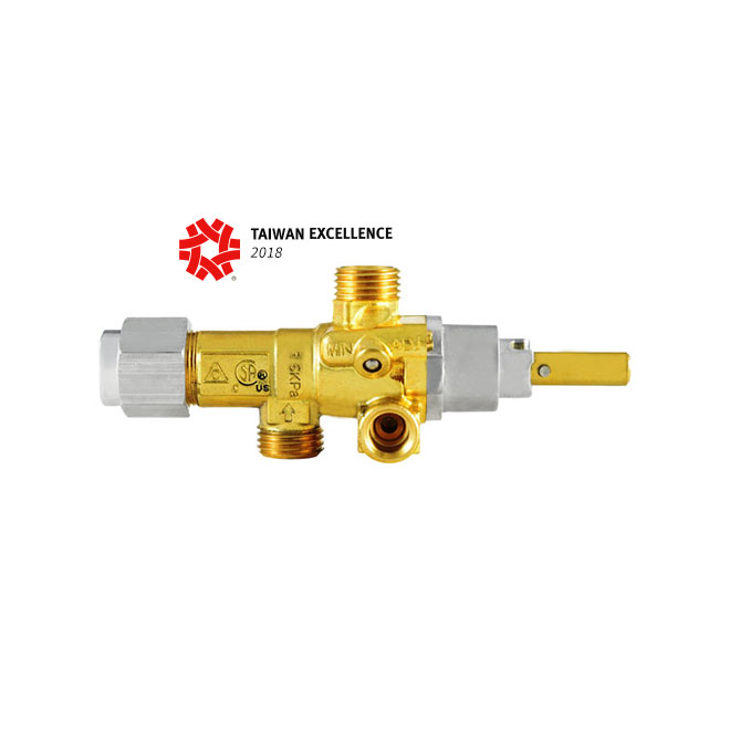
The functional standard conforms in all aspects to CSA, Delta C, CE, Gas Mark and JIA for international high quality standard, which complies with low pressure 1/2PSI gas appliances.
100% in-house quality assurance inspection with all gas valve for leakage testing procedures in strict conformance to safety regulations requirements for high precision and reliability.

The present invention relates to an improved control system and valve structure for gas ovens, and more particulaly to a system and valve structure for preventing unsafe conditions due to opening of the oven door or absence of a standing pilot flame.
For reasons of safety is it desirable to prevent operation of a gas oven when the oven door is open. For one example, in mobile homes and other recreational vehicles gas ovens may be designed to use outside air for combustion. In this situation, operation of the oven with the door open can defeat this arrangement and cause dangerous oxygen depletion within the vehicle. Moreover, operation of any oven with the door open produces other safety problems such as the danger of fire.
In many oven installations there is provided a small standing pilot flame for igniting a control pilot flame and/or for igniting the main oven burner. It is undesirable to admit gas to the oven when the standing pilot flame does not exist. This problem is of importance in mobile homes and recreational vehicle installations because the standing pilot gas is normally shut off while the vehicle is in motion and the standing pilot flame must periodically be reestablished.
Important objects of the present invention are to provide an improved system and an improved valve structure for controlling pilot gas flow in an oven so that the oven cannot be operated when the oven door is open or when no standing pilot flame is present; to provide an improved pilot control valve structure; and to provide a novel arrangement for controlling gas flow to the oven in dependence upon the position of the oven door and in dependence upon the presence or absence of a standing pilot flame.
Briefly, the above and other objects and advantages of the invention are achieved by the provision of an improved system and valve structure for a gas oven including an oven door movable between closed and opened positions and a main over burner disposed within the oven. A pilot burner located adjacent the main burner produces a standby pilot flame and a control pilot flame in response to the supply of a pilot flame gas flow and a control flame gas flow. A safety valve admits gas to the main burner in response to presence of the control pilot flame. An oven control provides the standing pilot gas flow and the control pilot gas flow by way of a novel pilot valve structure.
In accordance with one feature of the invention, the pilot valve structure includes a valve serving to interrupt the control pilot gas flow whenever the oven door is moved from its closed position. Consequently, no control pilot flame is present when the oven door is opened, and as a result of operation of the safety valve, no gas is admitted to the main burner. However, during opening of the oven door, the standby pilot flame continues to exist.
The pilot valve structure includes a single outlet for supplying both standing and control pilot gas flows to the dual rate pilot. The valve structure includes a first inlet for receiving control pilot flow and a second inlet for receiving standing pilot flow. A first valve member interrupts all flow to the dual rate pilot in its normally closed position and is movable to an open position by manual operation in order to light the standing pilot flame and thereafter is held in open position by means of a flame sensor disposed adjacent the standing pilot flame. The door responsive control pilot flow valve is disposed in the housing of the pilot valve structure, and serves to control flow through the control pilot flow inlet in response to position of the oven door.
FIG. 1 is a largely schematic and diagrammatic simplified view of a gas oven including an oven control system and valve structure embodying the principles of the present invention;
Having reference now to FIG. 1 of the drawing, there is illustrated an oven control system designated as a whole by the reference numeral 10 and constructed in accordance with the principles of the present invention. The oven control system 10 is associated with an oven 12, illustrated only in part, and includes a novel pilot control valve structure generally designated as 14 constructed in accordance with features of the present invention. The system 10 and valve structure 14 may be incorporated into any desired type of oven installation, and for purposes of example the illustrated oven 12 is associated with a free standing range including a door 16 hingedly mounted upon an oven front wall 18 for movement between open and closed positions. In accordance with important features of the invention, the system 10 and valve structure 14 prevent operation of the oven when the oven door is opened, and prevent admission of gas to the oven when no standing pilot flame is present.
In order to heat the interior of the oven 12 there is provided a main oven burner 20 disposed beneath a flame shield 22 at the bottom of the oven 12. Disposed adjacent the main burner 20 is a pilot burner 24 capable of producing a continuing standing pilot flame and an intermittent control pilot flame in response to the flow of gas into the pilot burner 24 at lesser and greater rates of flow.
Fuel is supplied to the main burner 20 from a gas supply manifold 26 by way of an oven control 28, a conduit 30, a safety valve 32 and a conduit 34. Although the oven control system 10 of the present invention may be adapted for many different types of oven installations and may make use of many different types of oven controls, the control 28 of the illustrated arrangement is of the type disclosed and claimed in U. S. Pat. No. 3,563,457 -- Bergquist et al. This control includes an operating knob 36 for controlling the operation of the oven 12.
More specifically, the operating knob 36 of the control 28 may be moved to a "pilot off" position wherein no gas flows from the manifold 26 into the oven control system 10. This position is useful in connection with gas ovens of mobile homes, recreational vehicles and the like wherein all gas is shut off during movement of the vehicle. In order to condition the oven 12 for use, the knob 36 is moved from the "pilot off" to an "off" position wherein gas is admitted through the control 28 only to a standing pilot supply conduit 38 and not to other components of the system. As appears more fully below, gas flowing through conduit 38 produces a standing pilot flame at the pilot burner 24 serving as a continuing source of ignition within the oven 12.
Operating knob 36 is movable from the "off" position to a variety of operating positions wherein desired oven cooking temperatures are thermostatically maintained. In such positions the oven temperature is maintained at the temperature selected through setting of the knob 36 by the admission of fuel from the manifold 26 through the control 28 to a control pilot supply conduit 40 and to the conduit 30 and safety valve 32 as well as to the standing pilot supply conduit 38. Reference may be had to said U.S. Pat. No. 3,563,457 for a further description of the structure and operation of the oven control 28 beyond that necessary for an understanding of the present invention.
Admission of fuel from the control 28 and conduit 40 to the pilot 24, under the control of the valve structure 14 as described below, results in admission of fuel to the oven burner 20. More specifically, fuel flowing from the valve structure 14 to the pilot 24 through a conduit 42 enters through an inlet fitting 44 (FIGS. 2, 3 and 4) to a tubular pilot body 46 and is mixed with primary air entrained through an aeration aperture 48. The outlet end of tube 46 includes an upper outlet 50 and a lower outlet 52, and a deflector 54 is spaced from the end of the tubular body 46.
The standing and control pilot flames produced by pilot 24 are illustrated in FIGS. 3 and 4. When standing pilot fuel flow provided to the pilot 24 from control 28 through conduit 38, valve structure 14 and conduit 42 is ignited, a standing pilot flame designated by reference numeral 56 and indicated by broken lines in FIGS. 3 and 4 is produced. This standing pilot flame impinges upon a flame sensing device comprising a fluid charged blub 58 communicating by way of a conduit 60 with the valve structure 14.
When flow to the pilot 24 is augmented by the control pilot gas flow from the control 28, conduit 40, valve structure 14 and conduit 42, the flame at the pilot 24 extends into the deflector 54, and is partly deflected downward to produce the control pilot flame 62 shown in broken lines in FIG. 4. Standing pilot flame 56 continues to exist at upper pilot outlet 50 while the control pilot flame is produced at the lower outlet 52. The control pilot flame impinges upon a flame sensing device comprising a fluid charged bulb 64 communicating with safety valve 32 by way of a conduit 66.
Having reference now to the safety valve 32, this type of valve is well known to those skilled in the art, and any commercially available valve could be used in the system 10. One example of such a safety valve may be found in U.S. Pat. No. 3,469,781 -- Sekera, Jr. Valve 32 includes an inlet 68 connected to the control 28 by conduit 30 and an outlet 70 communicating with the burner 20 by way of conduit 34. The function of the safety valve 32 is to permit the flow of gas into the main burner 20 only during such time as a control pilot flame 62 is sensed at the pilot burner 24 by bulb 64. Heating of bulb 64 causes the valve 32 to be operated from its closed condition to its open condition in response to the establishment of a control pilot flame 62, and cooling of bulb 64 in the absence of a control pilot flame 62 results in closing of the valve 32. Reference may be had to said U.S. Pat. No. 3,469,781 for a further description of the structure and operation of the safety valve 32.
In accordance with important features of the present invention, the pilot control valve structure 14 is provided in the oven control system 10 in order to prevent unsafe operation of the oven 12 when no standing pilot flame 56 is present and/or when the oven door 16 is moved from its closed to its open position. In general, the valve structure 14 includes a housing 76 closed by a cover plate 78 and having an inlet 80 communicating with the standing pilot supply conduit 38, an inlet 82 communicating with the control pilot supply conduit 40, and an outlet 84 communicating by way of the conduit 42 with the pilot burner 24.
Unsafe operation of the oven when the oven door is open is prevented by means of a valve generally designated as 86 incorporated in the valve structure 14. The valve 86 is controlled by a door responsive operating linkage 88 to open communication between the control pilot supply conduit 40 and the pilot 24 only when the oven door 16 is in its closed position, and to prevent the flow of gas to the pilot 24 when the oven door 16 is in its open position.
Undesirable admission of fuel to the oven 12 when no standing pilot flame 56 has been established is prevented by means of a valve generally designated as 90 controlling flow through the outlet 84 of the valve structure 14 to the pilot 24. Valve 90 is normally closed and can be moved to its open position by means of a manual operating linkage 92, and can be maintained in its open position by a standing pilot flame responsive operating linkage 94.
Referring more specifically now to the valve structure 14, the two valves generally designated as 86 and 90 are of similar construction. Each includes a movable valve member including a reciprocating slider element 96 movable in a bore in the housing wall and provided with grooves 98 for flow of gas through the valve when in its open position. A washer 100 is press fitted onto each slider element 96 to retain an O-ring seal 102 in position between the washer 100 and the housing. Normally a spring 104 held in compression between the washer 100 and a spring retainer and fitting element 106 forces the O-ring seal 102 into sealing relation between the washer 100 and the housing 76 in order to maintain the respective valve 86 or 90 in its normally closed position. Each slider element 96 is provided with an operating pin 108 extending into the interior of the housing 76 for moving the slider element 96 against force of the spring 104 in order to open the respective valve 86 or 90.
In accordance with a feature of the invention, the valve 86 permits gas to flow to the pilot 24 to produce the control pilot flame 62 only when the oven door 16 is moved to its closed position. When oven door 16 is open, the valve 86 is in its closed position as illustrated in FIG. 2 of the drawings and no fuel flows from the conduit 40 to the pilot 24 through the valve 86. As a result, no control pilot flame 62 is established and the valve 32 does not open to admit fuel to the oven burner 20.
In order to operate the valve 86 between positions, the cover plate 78 of the valve structure 14 carries a boss 110 slidably supporting a push pin 112 carrying a push plate 114. A spring 116 held in compression between the boss 110 and the plate 114 holds the pin 112 in its normal position illustrated in FIG. 2 when the oven door is open. When the oven door is closed, the door responsive operating linkage 88 (FIG. 1) which may include any suitable force transmitting structure indicated by broken lines 117 coupled between a door guide 118 and a push rod 120 or other pushing device engages the push plate 114 and forces the push pin 112 into the housing 76 by overcoming the force of the spring 116. The end of the pin 112 engages and depresses the operating pin 108 of the slider element 96 thus opening the valve 86 and permitting fuel to flow from the inlet 82 through the housing 76 and from the outlet 80 through the conduit 42 to the pilot 24.
In accordance with another feature of the invention, the structure 14 includes the valve 90 for preventing the admission of any fuel to the oven 12 until such time as a standing pilot flame 56 is established. When no standing pilot flame is present, the valve 90 is in its normally closed position as illustrated in FIG. 2 of the drawing. In order to condition the oven for operation, a standing pilot flame 56 is established. In order to permit gas to flow to the pilot 24 in order to ignite a standing flame, the operator of the oven first operates the manual linkage 92 in order to open the valve 90. With reference to FIG. 1, it can be seen that in the illustrated arrangement the manual linkage 92 includes a push button 122 movable within a housing 124 supported in the front wall 18 of the oven. When the push button is depressed against the force of a push button spring 126 a suitable force transmitting arrangement designated by a broken line 128 moves a push rod 130 in order to open the valve 90.
The valve 90 is manually controlled in response to movement of the push rod 130 by means of a push pin 132 (FIGS. 2-4) reciprocally supported by a boss 134 in the cover plate 78 and normally held in the position illustrated in FIG. 2 by means of a spring 136 held in compression between the boss 134 and a push plate 138. When the push rod 130 moves against the push plate 138, the pin 132 moves into housing 76 to depress the operating pin 108 of the slider element 96 thereby to open the valve 90.
Once the valve 90 has been opened by operation of the manual linkage 92 and fuel is flowing to the pilot 24, the standing pilot flame 56 is ignited by a match or other suitable ignition means. When the standing pilot flame 56 is established as illustrated in FIG 3 of the drawings, the flame heats the standing pilot flame sensing bulb 58 causing expansion of the fluid held therein. This expansion is accommodated by an expansible diaphragm 140 disposed within the housing 76 and communicating with the bulb 58 through conduit 60. Expansion of diaphragm 14 causes a power element 142 to pivot an operating lever 144 of the flame responsive operating linkage 96 around a pivot member 146. The lever depresses the operating pin 108 of the valve 90 to hold the valve 90 open so long as the standing pilot flame 56 continues.
The operation of the oven control system 10 and of the pilot control valve structure 14 will be apparent to those skilled in the art in view of the preceding detailed description. Briefly, the structure 14 is shown in FIGS. 1 and 2 in a non-operating or fully shut down condition wherein the oven door 16 is open and wherein no flame exists at the pilot 24. In this condition, the valves 86 and 90 of the valve structure 14 are both closed and no gas is admitted to the pilot burner 24. In addition, the valve 32 is closed in the absence of a control pilot flame 62 and no gas is admitted to the main oven burner 20.
In order to prepare the oven 12 for operation, the operating knob 36 of the oven control 28 is moved from the "pilot off" to the "off" position so that communication is established to the standing pilot flow conduit 38 leading to the inlet 80 of the valve structure 14. The push button 122 is depressed and to open the valve 90 and establish communication between the conduit 38 and the conduit 42 and pilot 24. The gas flowing from the pilot 24 is ignited and, as illustrated in FIG. 3, the standing pilot flame is produced. The standing pilot flame 56 heats the bulb 58 and the diaphragm 140 expands and lever 144 holds the valve 90 in its open position. At this time the push button 122 may be released by the operator of the oven 12 and the valve 90 will nevertheless be maintained in its open position by the continuing standing pilot flame 56.
The standing pilot flame 56 continues to burn to maintain a continuing source of ignition in the oven 12. In order to carry out a cooking operation with the oven 12, the oven door 16 is closed. When this occurs, the valve 86 is opened to permit the flow of fuel from the control pilot flow conduit 40 through the valve structure 14 and conduit 42 to the pilot 24. When the operating knob 36 of the control 28 is moved to an operating position, gas flows through conduits 40 and 42 to the pilot burner 24, and as illustrated in FIG. 4 a control pilot flame 62 is established. Simultaneously, the control 28 admits gas to the conduit 30 and inlet 68 of the valve 32. When the control pilot flame 62 heats the bulb 64, the valve 32 is operated to its open condition and fuel flows through the valve 32 and conduit 34 to the main burner 20 where it is ignited by flame at the pilot burner 24.
If at any time during operation of the oven the oven door 16 is moved from its closed position, flame at the main burner 20 is discontinued and the control pilot flame 62 at the pilot burner 24 is also discontinued while the standing flame is permitted to continue for reignition when the door is closed. More specifically, when the door 16 is open, the door responsive operating linkage 88 causes the valve 86 to close to prevent flow from the control pilot flow conduit 40 through the inlet 82 into the valve structure 14. As a result the control pilot flame 62 is discontinued and the bulb 64 cools. The safety valve 32 then closes to discontinue flow into the main burner 20 until such time as the oven door 16 is reclosed.

Besides the P/T value of the sleeve the limitations of the valve bodies also have to be considered. Please refer to the EN 12516-1 resp. ASME B16.34 in order to choose a proper pressure rating (PN/class). The shown values refer to austenitic stainless steel 1.4408 (A351 Gr. CF8M).

This website is using a security service to protect itself from online attacks. The action you just performed triggered the security solution. There are several actions that could trigger this block including submitting a certain word or phrase, a SQL command or malformed data.

In order to ensure that the maximum allowable accumulation pressure of any system or apparatus protected by a safety valve is never exceeded, careful consideration of the safety valve’s position in the system has to be made. As there is such a wide range of applications, there is no absolute rule as to where the valve should be positioned and therefore, every application needs to be treated separately.
A common steam application for a safety valve is to protect process equipment supplied from a pressure reducing station. Two possible arrangements are shown in Figure 9.3.3.
The safety valve can be fitted within the pressure reducing station itself, that is, before the downstream stop valve, as in Figure 9.3.3 (a), or further downstream, nearer the apparatus as in Figure 9.3.3 (b). Fitting the safety valve before the downstream stop valve has the following advantages:
• The safety valve can be tested in-line by shutting down the downstream stop valve without the chance of downstream apparatus being over pressurised, should the safety valve fail under test.
• When setting the PRV under no-load conditions, the operation of the safety valve can be observed, as this condition is most likely to cause ‘simmer’. If this should occur, the PRV pressure can be adjusted to below the safety valve reseat pressure.
Indeed, a separate safety valve may have to be fitted on the inlet to each downstream piece of apparatus, when the PRV supplies several such pieces of apparatus.
• If supplying one piece of apparatus, which has a MAWP pressure less than the PRV supply pressure, the apparatus must be fitted with a safety valve, preferably close-coupled to its steam inlet connection.
• If a PRV is supplying more than one apparatus and the MAWP of any item is less than the PRV supply pressure, either the PRV station must be fitted with a safety valve set at the lowest possible MAWP of the connected apparatus, or each item of affected apparatus must be fitted with a safety valve.
• The safety valve must be located so that the pressure cannot accumulate in the apparatus viaanother route, for example, from a separate steam line or a bypass line.
It could be argued that every installation deserves special consideration when it comes to safety, but the following applications and situations are a little unusual and worth considering:
• Fire - Any pressure vessel should be protected from overpressure in the event of fire. Although a safety valve mounted for operational protection may also offer protection under fire conditions,such cases require special consideration, which is beyond the scope of this text.
• Exothermic applications - These must be fitted with a safety valve close-coupled to the apparatus steam inlet or the body direct. No alternative applies.
• Safety valves used as warning devices - Sometimes, safety valves are fitted to systems as warning devices. They are not required to relieve fault loads but to warn of pressures increasing above normal working pressures for operational reasons only. In these instances, safety valves are set at the warning pressure and only need to be of minimum size. If there is any danger of systems fitted with such a safety valve exceeding their maximum allowable working pressure, they must be protected by additional safety valves in the usual way.
In order to illustrate the importance of the positioning of a safety valve, consider an automatic pump trap (see Block 14) used to remove condensate from a heating vessel. The automatic pump trap (APT), incorporates a mechanical type pump, which uses the motive force of steam to pump the condensate through the return system. The position of the safety valve will depend on the MAWP of the APT and its required motive inlet pressure.
This arrangement is suitable if the pump-trap motive pressure is less than 1.6 bar g (safety valve set pressure of 2 bar g less 0.3 bar blowdown and a 0.1 bar shut-off margin). Since the MAWP of both the APT and the vessel are greater than the safety valve set pressure, a single safety valve would provide suitable protection for the system.
Here, two separate PRV stations are used each with its own safety valve. If the APT internals failed and steam at 4 bar g passed through the APT and into the vessel, safety valve ‘A’ would relieve this pressure and protect the vessel. Safety valve ‘B’ would not lift as the pressure in the APT is still acceptable and below its set pressure.
It should be noted that safety valve ‘A’ is positioned on the downstream side of the temperature control valve; this is done for both safety and operational reasons:
Operation - There is less chance of safety valve ‘A’ simmering during operation in this position,as the pressure is typically lower after the control valve than before it.
Also, note that if the MAWP of the pump-trap were greater than the pressure upstream of PRV ‘A’, it would be permissible to omit safety valve ‘B’ from the system, but safety valve ‘A’ must be sized to take into account the total fault flow through PRV ‘B’ as well as through PRV ‘A’.
A pharmaceutical factory has twelve jacketed pans on the same production floor, all rated with the same MAWP. Where would the safety valve be positioned?
One solution would be to install a safety valve on the inlet to each pan (Figure 9.3.6). In this instance, each safety valve would have to be sized to pass the entire load, in case the PRV failed open whilst the other eleven pans were shut down.
If additional apparatus with a lower MAWP than the pans (for example, a shell and tube heat exchanger) were to be included in the system, it would be necessary to fit an additional safety valve. This safety valve would be set to an appropriate lower set pressure and sized to pass the fault flow through the temperature control valve (see Figure 9.3.8).

The primary purpose of a safety valve is to protect life, property and the environment. Safety valves are designed to open and release excess pressure from vessels or equipment and then close again.
The function of safety valves differs depending on the load or main type of the valve. The main types of safety valves are spring-loaded, weight-loaded and controlled safety valves.
Regardless of the type or load, safety valves are set to a specific set pressure at which the medium is discharged in a controlled manner, thus preventing overpressure of the equipment. In dependence of several parameters such as the contained medium, the set pressure is individual for each safety application.

A safety valve must always be sized and able to vent any source of steam so that the pressure within the protected apparatus cannot exceed the maximum allowable accumulated pressure (MAAP). This not only means that the valve has to be positioned correctly, but that it is also correctly set. The safety valve must then also be sized correctly, enabling it to pass the required amount of steam at the required pressure under all possible fault conditions.
Once the type of safety valve has been established, along with its set pressure and its position in the system, it is necessary to calculate the required discharge capacity of the valve. Once this is known, the required orifice area and nominal size can be determined using the manufacturer’s specifications.
In order to establish the maximum capacity required, the potential flow through all the relevant branches, upstream of the valve, need to be considered.
In applications where there is more than one possible flow path, the sizing of the safety valve becomes more complicated, as there may be a number of alternative methods of determining its size. Where more than one potential flow path exists, the following alternatives should be considered:
This choice is determined by the risk of two or more devices failing simultaneously. If there is the slightest chance that this may occur, the valve must be sized to allow the combined flows of the failed devices to be discharged. However, where the risk is negligible, cost advantages may dictate that the valve should only be sized on the highest fault flow. The choice of method ultimately lies with the company responsible for insuring the plant.
For example, consider the pressure vessel and automatic pump-trap (APT) system as shown in Figure 9.4.1. The unlikely situation is that both the APT and pressure reducing valve (PRV ‘A’) could fail simultaneously. The discharge capacity of safety valve ‘A’ would either be the fault load of the largest PRV, or alternatively, the combined fault load of both the APT and PRV ‘A’.
This document recommends that where multiple flow paths exist, any relevant safety valve should, at all times, be sized on the possibility that relevant upstream pressure control valves may fail simultaneously.
The supply pressure of this system (Figure 9.4.2) is limited by an upstream safety valve with a set pressure of 11.6 bar g. The fault flow through the PRV can be determined using the steam mass flow equation (Equation 3.21.2):
Once the fault load has been determined, it is usually sufficient to size the safety valve using the manufacturer’s capacity charts. A typical example of a capacity chart is shown in Figure 9.4.3. By knowing the required set pressure and discharge capacity, it is possible to select a suitable nominal size. In this example, the set pressure is 4 bar g and the fault flow is 953 kg/h. A DN32/50 safety valve is required with a capacity of 1 284 kg/h.
Where sizing charts are not available or do not cater for particular fluids or conditions, such as backpressure, high viscosity or two-phase flow, it may be necessary to calculate the minimum required orifice area. Methods for doing this are outlined in the appropriate governing standards, such as:
Coefficients of discharge are specific to any particular safety valve range and will be approved by the manufacturer. If the valve is independently approved, it is given a ‘certified coefficient of discharge’.
This figure is often derated by further multiplying it by a safety factor 0.9, to give a derated coefficient of discharge. Derated coefficient of discharge is termed Kdr= Kd x 0.9
Critical and sub-critical flow - the flow of gas or vapour through an orifice, such as the flow area of a safety valve, increases as the downstream pressure is decreased. This holds true until the critical pressure is reached, and critical flow is achieved. At this point, any further decrease in the downstream pressure will not result in any further increase in flow.
A relationship (called the critical pressure ratio) exists between the critical pressure and the actual relieving pressure, and, for gases flowing through safety valves, is shown by Equation 9.4.2.
For gases, with similar properties to an ideal gas, ‘k’ is the ratio of specific heat of constant pressure (cp) to constant volume (cv), i.e. cp : cv. ‘k’ is always greater than unity, and typically between 1 and 1.4 (see Table 9.4.8).
For steam, although ‘k’ is an isentropic coefficient, it is not actually the ratio of cp : c. As an approximation for saturated steam, ‘k’ can be taken as 1.135, and superheated steam, as 1.3. As a guide, for saturated steam, critical pressure is taken as 58% of accumulated inlet pressure in absolute terms.
Overpressure - Before sizing, the design overpressure of the valve must be established. It is not permitted to calculate the capacity of the valve at a lower overpressure than that at which the coefficient of discharge was established. It is however, permitted to use a higher overpressure (see Table 9.2.1, Module 9.2, for typical overpressure values). For DIN type full lift (Vollhub) valves, the design lift must be achieved at 5% overpressure, but for sizing purposes, an overpressure value of 10% may be used.
For liquid applications, the overpressure is 10% according to AD-Merkblatt A2, DIN 3320, TRD 421 and ASME, but for non-certified ASME valves, it is quite common for a figure of 25% to be used.
Backpressure - The sizing calculations in the AD-Merkblatt A2, DIN 3320 and TRD 421 standards account for backpressure in the outflow function,(Ψ), which includes a backpressure correction.
Two-phase flow - When sizing safety valves for boiling liquids (e.g. hot water) consideration must be given to vaporisation (flashing) during discharge. It is assumed that the medium is in liquid state when the safety valve is closed and that, when the safety valve opens, part of the liquid vaporises due to the drop in pressure through the safety valve. The resulting flow is referred to as two-phase flow.
The required flow area has to be calculated for the liquid and vapour components of the discharged fluid. The sum of these two areas is then used to select the appropriate orifice size from the chosen valve range. (see Example 9.4.3)
Many standards do not actually specify sizing formula for two-phase flow and recommend that the manufacturer be contacted directly for advice in these instances.

As a design engineer responsible for developing and specifying boilers, dryers, furnaces, heaters, ovens and other industrial heating equipment, you face a daunting labyrinth of standards and industry regulations. Regulatory bodies sound a bit like alphabet soup, with acronyms like UL, FM, CSA, UR, AGA, ASME, ANSI, IRI, CE and NFPA tossed about. This article will help explain a common task for many thermal processing equipment specifiers: meeting the requirements of key codes — including Underwriters Laboratories (UL), Factory Mutual Insurers (FM) and the National Fire Protection Association (NFPA) — for safety valve equipment used in process heating applications.
Key to designing safety into your fuel train configurations are familiar technologies such as safety shutoff valves and vent valves as well as visual-indication mechanisms and proof-of-closure switches.
Your design skills come into play with how you take advantage of the wide range of products available. You can mix and match solenoid and safety shutoff valves — within designs from catalytic reactors to multi-zone furnaces — to create easily installed, cost-effective solutions that comply with all necessary standards. (See table.)
Make sure, however, that you start with a good grasp of valve element fundamentals. For example, examining a proof-of-closure (POC) switch underlines how reliably modern valves can ensure combustion safety. The POC unit provides an electrical contact interlocked with the controller safety circuit. In a typical design, the switch is located at the bottom of the valve, positioned to trace the stroke of the valve disc. When the disc seal reaches the fully closed position, it triggers the mechanism to push down on the contact, closing it and triggering the unit’s visual indicator to show open or closed status. As a result, the operator can act with full confidence in situations where it is critical that a safety valve be safely closed.
To provide ease of installation, many users prefer valves with modular capabilities. For example, to reduce mounting complexity, you can choose modular gas safety shut-off valves — combining a solenoid valve with an electrohydraulic motorized valve for a compact double-valve footprint, a slow-open feature and high flow rates. An accompanying actuator can provide on/off or high/low/off firing rates as well as visual indication and proof of closure for compliance with most industry standards.
Also, you may want to look for valves that include useful features such as pipe taps, which can facilitate accurate pressure readings and leakage testing.
Knowing your valve choices — and how they meet given codes and standards — can reduce the time required for design and production while facilitating compliance. This results in safer, more efficient and cost-effective heating process installations.
From time to time, you may find it necessary to turn off the gas for a stove (or other appliance) that heats with natural gas or LP (liquid propane) gas. Several common repairs for stoves and other appliances may require that you shut off the gas. And should you ever detect a faint odor of gas in your home, shutting off the gas may be required.
Furnaces, water heaters, space heaters, stoves, ovens, and cooktop ranges can all be powered by gas, so it"s a good idea to know where the gas shutoff valves are located on any of these appliances.
It"s a good idea to make a point of knowing where the gas shutoff valves are located for your range and all other gas appliances in your home. In the event that you smell gas, don"t spend a lot of time searching for the appliance shutoff valves if you don"t already know where they are.
Building codes require the gas shutoff valve to be located within 6 feet of the appliance and in the same room. If you find an improper situation that doesn"t meet the code requirements, it"s a good idea to have a service person install a proper shutoff valve. Shutoff valves for standard (freestanding) gas stoves or ranges typically are located behind the appliance.
Any time there is a gas leak in one of your appliances, there is the possible danger of an immediate and catastrophic explosion or fire, so the official recommendation from most utility companies is to leave your house immediately if you smell gas, then call the utility company. Only if the odor is faint should you take the time to find the shutoff valve to an appliance to stop the flow of gas. Shutting off the gas to the stove yourself is safe only if the gas odor is faint and is clearly coming from the stove area.
If a gas smell permeates the entire house, or you detect a strong smell when you walk inside your home, leave the house immediately and call 911from a locationwell away from your house.
If the odor of gas is faint and is contained in a small area, you can shut off the gas yourself before calling the utility or a plumber. In many instances, the location of the gas smell will give you a strong hint about what appliance is malfunctioning or where the bad connection is located. If you smell gas in the kitchen, for example, it"s quite likely that the problem lies with the stove or range. When the smell of gas is localized in this way, it is usually safe to act quickly to turn off the gas supply to the appliance itself, but always use your best judgment, and err on the side of safety.


 8613371530291