
accumulator safety valve brands

The three-way ball valve is used to detect the safety valve type VS224 and to remove it for periodic recalibration, without having to fully di-scharge all the nitrogen of accumulator/accumulator station. The ball of the valve is located between two pre- compressed seals provided with a floating system, so it is guaranteed a perfect seal at both low and high pressure.

Distributor of hydraulic press safety, quick opening safety, rotary and safety valves. Amerigear®, Boston Gear®, Carlisle®, DeMag®, Desch® and IMI Norgren®, pneumatic, double action, quick release and flow control valves also provided. Repair and preventative maintenance services are offered. Value added services such as custom barcoding, CAD capabilities, OEM assembly, plant surveys and third party logistics are also available. Serves the metal processing, metal service center, paper mill and paper converting, canning, grinding, commercial laundry, marine, oil and gas and material handling industries. Vendor managed inventory (VMI) programs available. Kanban delivery.
ISO 9001:2015 certified. Manufacturer of high and low pressure proportional relief valves made from 316 stainless steel. Available up to 6,000 psig working pressure and -17 degrees C to +148 degrees C operating temperature. Features vary depending upon model, including leak tight design, end connections, O-rings, steam seals, locknuts, manual override handles and nitrile rubber seals. Designed to protect pressure sensitive equipment by relieving pressure upstream of the equipment. Used in oil, gas, chemical, pharmaceutical and laboratory applications. Also suitable for steam cleaning and sterilization system, heating line, dispensing and filling system applications. Lean manufacturing capable. RoHS and REACH compliant. Made in the USA.

An accumulator safety blockis a multi-functional valve generally placed between the operating system and the hydraulic accumulator. The safety block acts as isolation for the accumulator, especially in cases where you need to repair or test the system for varied purposes.
Basically, the safety block will act as a pressure relief valve or an emergency shut-off device to protect your hydraulic system from system failure or over-pressurization.
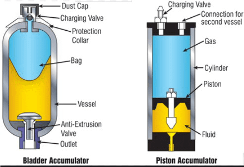
Most accumulator safety blocks from AstaFluid are ideally suited to be used with different types of accumulators, including the diaphragm, bladder, and even piston. The multi-functional and compact design of an accumulatorsafety valveis designed with the intent to reduce connections and save space. This allows you to boost your productivity and increase profits with maximum output and minimal downtime.
Fairbanks Morse Defense and Hunt Valve have been delivering fluid power engineering innovations and solutions to our core defense and industrial customers for decades. With unmatched reliability, we specialize in severe-duty valves and complementary engineered components and system solutions for the defense and industrial markets, including primary metals, energy and process.
Specializing in harsh environments, our experts in extreme engineering design and support the manufacturing of durable and reliable valves that stand up to the toughest applications.

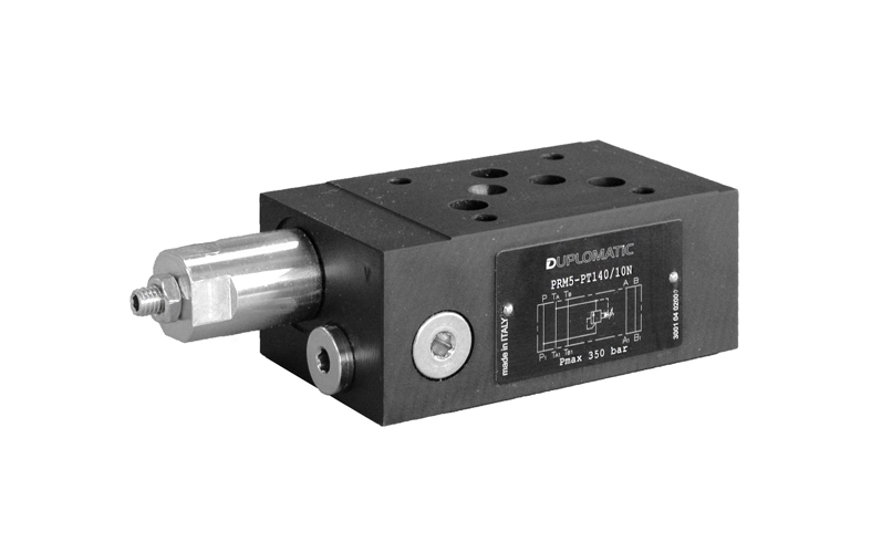
To ensure reliable operation, direct-operated pressure relief valves are used in most cases. These are - in contrast to the pilot-operated pressure relief valves - less sensitive to contamination and have lower leakage.
There are additional requirements that should be followed by the design of the pressure valve:Damping of the valve cone with a suitable degree of damping, while complying with the valve stability and reaction speed
As a well-known manufacturer of hydraulic valves, control blocks and complete hydraulic systems, ARGO-HYTOS extends its product portfolio to include the pressure relief valve SR1A-B2, which was generally designed for use in hydraulic accumulator circuits.
This is a direct-operated pressure relief valve in screw-in design 7 / 8-14UNF. The structure of a poppet valve ensures minimal leakage when the valve is closed. By optimizing the damping behavior, a very good valve dynamic could be achieved while maintaining a stable function. The maximum operating pressure is 420 bar, the maximum flow rate is 60 l/min. For a precise pressure setting, 7 valve pressure levels are at the customer’s disposal. The opening pressure can be adjusted in the respective pressure level range by an adjusting screw and secured with a lock nut. It is also possible to obtain the valve in preset condition (setting sealed).
With regard to the surface protection, the valve body and the adjustment screw are zinc-coated. The sleeve and the seat are protected by carbonitriding, which further optimizes the mechanical characteristics.
In order to be able to work in limited work spaces, the plastic cap was adjusted. The seals, either NBR or FKM enable the use of the valve at -30 °C up to +120 °C. The valve was certified by the TÜV Süd according to the application for hydraulic accumulator circuits.

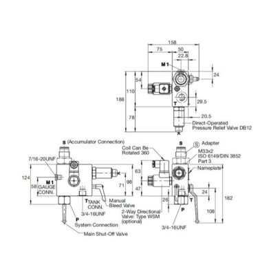
The hydraulic accumulator safety block HSB-06 is used for the prescribed protection and relief of hydraulic systems with pressure accumulators.It is possible to have a nominal size 06 installation without piping work by vertically linking them with a mounting plate. It is easy to add other functions, such as (throttle) check valves, by using standard sandwich plates. The internal connection of channels A, B and P offers additional connectivity options, including but not limited to accumulator, consumer or testing connections.The directly operated pressure relief valve has achieved the type examination and can be supplied as pre-set.
According to the PED 97/23/EC, the increase in system pressure caused by the volume flow must not be greater than 10% of the setpoint response pressure (setpoint pressure). Attention! Due to the increasing volume flow, the system pressure increases by the level of counterpressure in the return line (connection “T”). Before ordering a valve with a type approval certificate it must be ensured that the maximum allowable flow (qVmax) of the safety valve at the desired response pressure p is greater than the maximum possible flow rate of the system to be protected. Please consult the diagram on the data sheet regarding the area of application for the HSB-06. The specified maximum flow qVmax must not be exceeded. Discharge piping from safety valves must have a safe outlet.
Searching for tools to control the flow of your piping system? Explore one of the largest featured collections of products and discover a range of wholesale safety valve for accumulator on Alibaba.com. When you search for safety valve for accumulator and related items, you will be able to find many types of safety valve for accumulator varying in size, shape, use, and quality, all at prices in which are highly reasonable!
There are many uses of valves - mainly controlling the flow of fluids and pressure. Some examples include regulating water for irrigation, industrial uses for controlling processes, and residential piping systems. Magnetic valves like those using the solenoid, are often used in a range of industrial processes. Whereas backflow preventers are often used in residential and commercial buildings to ensure the safety and hygiene of the water supplies. Whether you are designing a regulation system for irrigation or merely looking for a new replacement, you will be able to find whatever type of safety valve for accumulator that you need. Our products vary from check valves to pressure reducing valves, ball valves, butterfly valves, thermostatic mixing valves, and a lot more.

In order to ensure that the maximum allowable accumulation pressure of any system or apparatus protected by a safety valve is never exceeded, careful consideration of the safety valve’s position in the system has to be made. As there is such a wide range of applications, there is no absolute rule as to where the valve should be positioned and therefore, every application needs to be treated separately.
A common steam application for a safety valve is to protect process equipment supplied from a pressure reducing station. Two possible arrangements are shown in Figure 9.3.3.
The safety valve can be fitted within the pressure reducing station itself, that is, before the downstream stop valve, as in Figure 9.3.3 (a), or further downstream, nearer the apparatus as in Figure 9.3.3 (b). Fitting the safety valve before the downstream stop valve has the following advantages:
• The safety valve can be tested in-line by shutting down the downstream stop valve without the chance of downstream apparatus being over pressurised, should the safety valve fail under test.
• When setting the PRV under no-load conditions, the operation of the safety valve can be observed, as this condition is most likely to cause ‘simmer’. If this should occur, the PRV pressure can be adjusted to below the safety valve reseat pressure.
Indeed, a separate safety valve may have to be fitted on the inlet to each downstream piece of apparatus, when the PRV supplies several such pieces of apparatus.
• If supplying one piece of apparatus, which has a MAWP pressure less than the PRV supply pressure, the apparatus must be fitted with a safety valve, preferably close-coupled to its steam inlet connection.
• If a PRV is supplying more than one apparatus and the MAWP of any item is less than the PRV supply pressure, either the PRV station must be fitted with a safety valve set at the lowest possible MAWP of the connected apparatus, or each item of affected apparatus must be fitted with a safety valve.
• The safety valve must be located so that the pressure cannot accumulate in the apparatus viaanother route, for example, from a separate steam line or a bypass line.
It could be argued that every installation deserves special consideration when it comes to safety, but the following applications and situations are a little unusual and worth considering:
• Fire - Any pressure vessel should be protected from overpressure in the event of fire. Although a safety valve mounted for operational protection may also offer protection under fire conditions,such cases require special consideration, which is beyond the scope of this text.
• Exothermic applications - These must be fitted with a safety valve close-coupled to the apparatus steam inlet or the body direct. No alternative applies.
• Safety valves used as warning devices - Sometimes, safety valves are fitted to systems as warning devices. They are not required to relieve fault loads but to warn of pressures increasing above normal working pressures for operational reasons only. In these instances, safety valves are set at the warning pressure and only need to be of minimum size. If there is any danger of systems fitted with such a safety valve exceeding their maximum allowable working pressure, they must be protected by additional safety valves in the usual way.
In order to illustrate the importance of the positioning of a safety valve, consider an automatic pump trap (see Block 14) used to remove condensate from a heating vessel. The automatic pump trap (APT), incorporates a mechanical type pump, which uses the motive force of steam to pump the condensate through the return system. The position of the safety valve will depend on the MAWP of the APT and its required motive inlet pressure.
This arrangement is suitable if the pump-trap motive pressure is less than 1.6 bar g (safety valve set pressure of 2 bar g less 0.3 bar blowdown and a 0.1 bar shut-off margin). Since the MAWP of both the APT and the vessel are greater than the safety valve set pressure, a single safety valve would provide suitable protection for the system.
Here, two separate PRV stations are used each with its own safety valve. If the APT internals failed and steam at 4 bar g passed through the APT and into the vessel, safety valve ‘A’ would relieve this pressure and protect the vessel. Safety valve ‘B’ would not lift as the pressure in the APT is still acceptable and below its set pressure.
It should be noted that safety valve ‘A’ is positioned on the downstream side of the temperature control valve; this is done for both safety and operational reasons:
Operation - There is less chance of safety valve ‘A’ simmering during operation in this position,as the pressure is typically lower after the control valve than before it.
Also, note that if the MAWP of the pump-trap were greater than the pressure upstream of PRV ‘A’, it would be permissible to omit safety valve ‘B’ from the system, but safety valve ‘A’ must be sized to take into account the total fault flow through PRV ‘B’ as well as through PRV ‘A’.
A pharmaceutical factory has twelve jacketed pans on the same production floor, all rated with the same MAWP. Where would the safety valve be positioned?
One solution would be to install a safety valve on the inlet to each pan (Figure 9.3.6). In this instance, each safety valve would have to be sized to pass the entire load, in case the PRV failed open whilst the other eleven pans were shut down.
If additional apparatus with a lower MAWP than the pans (for example, a shell and tube heat exchanger) were to be included in the system, it would be necessary to fit an additional safety valve. This safety valve would be set to an appropriate lower set pressure and sized to pass the fault flow through the temperature control valve (see Figure 9.3.8).

Emergency situations are not the only times relief valves are active; once installed they continuously regulate the flow of substance. They can also be pre-set to open when the pressure or temperature gets to a certain point that may be dangerous. Generally valves are placed on or near the pump head of the hose, pipe or tube. A wide variety of relief valve designs exist, although most resemble ball-check valves, swing check valves or diaphragm valves.
This last is particularly useful when controlling a flow of fluids that contains suspended solids. Most relief valves are spring operated, as are the majority of check valves. One specialized type of relief valve is known as a vacuum relief valve. As opposed to a normal relief valve, which relieves high pressure, a vacuum relief valve is used to relieve dangerously low pressures, or vacuums, by inserting air or an inert gas.
Like every other type of check valve, relief valves may be constructed from a variety of materials, including PVC, brass, ductile iron, copper, polyethylene, polypropylene, aluminum, steel, stainless steel and rubber. Which raw substance is used to produce each relief valve depends on the environment said relief valve will be in. The wrong product could result in erosion or contamination of the process stream. However, as long as research is done, finding the appropriate type of relief valve is possible. Every plumbing or fluid transfer application in the industrial, commercial and domestic arenas employ or will employ check valves. In fact, check valves of all kinds are an essential part of every day life. Because they need not be supervised to function and prevent product malfunction, check valves are not only desirable but often required by law to ensure the safety of water, gas and pressure applications.
We are counted amongst the top companies involved in offering an extensive range of Accumulator Safety Block. The offered safety blocks are provided in numerous specifications as per the requirements of customers.
Accident prevention authorities recommend the fitting of a pressure relief valve to gas loaded hydraulic accumulators. The OLAER Fawcett Christie range of carbon steel Accumulator Safety Block include features to make the installation, operation and maintenance of gas loaded hydraulic accumulators convenient and safe.
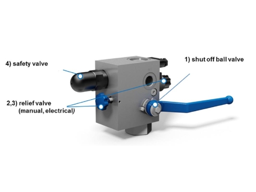
The MHA accumulator safety block of the ASB series combines all necessary functions to secure a hydraulic accumulator (either bladder, membrane or piston-type accumulator).
In case of emergency the operation of the shut off valve separates the accumulator from the hydraulic circuit. Afterwards the accumulator can be drained to the tank by using the manual (or as an option electrical) relief valve. In addition the accumulator is secured by a PED-certified pressure relief valve.


 8613371530291