
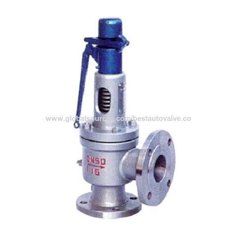
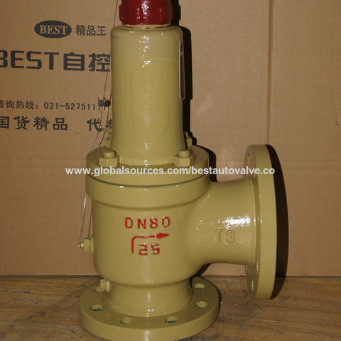
speed safety valve factory

Of all the challenges you face keeping your customers’ plants operating at full capacity, safety and relief valves shouldn’t be one of them. NASVI’s job is to give you the confidence that your valve supply chain is rock solid regardless the pressure it’s under.

In addition, we may disclose information collected from and about you as follows: (1) you expressly request or authorize us to do so ; (2) we believe the information is needed to comply with the law (for example, to comply with a search warrant, subpoena or court order), respond to a government request, enforce an agreement we have with you, or to protect our rights, property or safety, or the rights, property or safety of our employees or others ; (3) the information is provided to our agents, third parties or service providers who perform functions on our behalf ; (4) to address emergencies or acts of God ; (5) in anticipation of and in the course of an actual or potential sale, reorganization, consolidation, merger, or amalgamation of all or part of our business or operations in which case your information may be provided to the purchaser or resulting entity ; or (6) to address disputes, claims, or to persons holding a legal or beneficial interest.

With more than 1,050 employees and 130,000 safety valves produced per year, LESER is the largest manufacturer of safety valves in Europe and one of the leading companies in its industry worldwide.
LESER offers spring loaded and pilot operated safety valves for all industrial applications according to the Pressure Equipment Directive and ASME XIII. Major companies in the chemical, oil and gas, petrochemical, energy, technical gases, LNG/LPG, pharmaceutical, food and beverage, shipbuilding and heating and air conditioning industries use LESER safety valves.
LESER safety valves are developed for the international market in Hamburg and manufactured in the modern plant in Hohenwestedt/Germany. In addition, LESER produces safety valves to the same standards in India and China for the local markets. Nine subsidiaries and offices in Europe, America, the Middle East and Asia as well as authorized contacts in over 80 countries guarantee competent customer advice and fast, reliable deliveries.

24/7 Valve Service and Replacement - FAST Centers offer quick, localized testing and repair of valves, or the prompt installation of new Farris ASME certified valves.
Farris Engineering recognizes the value of having pressure relief valve experts as close to the customer as possible. This is accomplished through comprehensive training offered at the factory or on-site. FAST Center sales personnel and technicians are able to provide valuable experience to their customers.
Factory Trained Technicians - FAST technicians go through mandatory training consisting of classroom lecture and hands-on practical instruction on Farris Engineering pressure relief valves, repair procedures and applicable codes and standards. The result is a team of highly skilled technicians capable of handling both routine and complex pressure relief valve requirements around the world.
Local Inventory - Every FAST Center carries a large inventory of new pressure relief valves and spare parts, backed by a web-based global inventory exchange.
VR Certification - FAST Centers have VR certification issued by The National Board of Boiler and Pressure Vessel Inspectors to effectively and efficiently repair all pressure relief valves where applicable.

A safety valve must always be sized and able to vent any source of steam so that the pressure within the protected apparatus cannot exceed the maximum allowable accumulated pressure (MAAP). This not only means that the valve has to be positioned correctly, but that it is also correctly set. The safety valve must then also be sized correctly, enabling it to pass the required amount of steam at the required pressure under all possible fault conditions.
Once the type of safety valve has been established, along with its set pressure and its position in the system, it is necessary to calculate the required discharge capacity of the valve. Once this is known, the required orifice area and nominal size can be determined using the manufacturer’s specifications.
In order to establish the maximum capacity required, the potential flow through all the relevant branches, upstream of the valve, need to be considered.
In applications where there is more than one possible flow path, the sizing of the safety valve becomes more complicated, as there may be a number of alternative methods of determining its size. Where more than one potential flow path exists, the following alternatives should be considered:
This choice is determined by the risk of two or more devices failing simultaneously. If there is the slightest chance that this may occur, the valve must be sized to allow the combined flows of the failed devices to be discharged. However, where the risk is negligible, cost advantages may dictate that the valve should only be sized on the highest fault flow. The choice of method ultimately lies with the company responsible for insuring the plant.
For example, consider the pressure vessel and automatic pump-trap (APT) system as shown in Figure 9.4.1. The unlikely situation is that both the APT and pressure reducing valve (PRV ‘A’) could fail simultaneously. The discharge capacity of safety valve ‘A’ would either be the fault load of the largest PRV, or alternatively, the combined fault load of both the APT and PRV ‘A’.
This document recommends that where multiple flow paths exist, any relevant safety valve should, at all times, be sized on the possibility that relevant upstream pressure control valves may fail simultaneously.
The supply pressure of this system (Figure 9.4.2) is limited by an upstream safety valve with a set pressure of 11.6 bar g. The fault flow through the PRV can be determined using the steam mass flow equation (Equation 3.21.2):
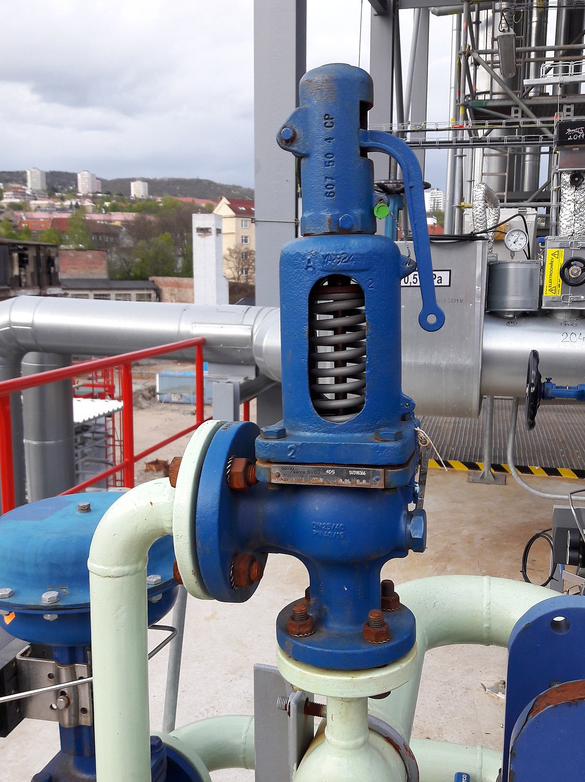
Once the fault load has been determined, it is usually sufficient to size the safety valve using the manufacturer’s capacity charts. A typical example of a capacity chart is shown in Figure 9.4.3. By knowing the required set pressure and discharge capacity, it is possible to select a suitable nominal size. In this example, the set pressure is 4 bar g and the fault flow is 953 kg/h. A DN32/50 safety valve is required with a capacity of 1 284 kg/h.
Coefficients of discharge are specific to any particular safety valve range and will be approved by the manufacturer. If the valve is independently approved, it is given a ‘certified coefficient of discharge’.
This figure is often derated by further multiplying it by a safety factor 0.9, to give a derated coefficient of discharge. Derated coefficient of discharge is termed Kdr= Kd x 0.9
Critical and sub-critical flow - the flow of gas or vapour through an orifice, such as the flow area of a safety valve, increases as the downstream pressure is decreased. This holds true until the critical pressure is reached, and critical flow is achieved. At this point, any further decrease in the downstream pressure will not result in any further increase in flow.
A relationship (called the critical pressure ratio) exists between the critical pressure and the actual relieving pressure, and, for gases flowing through safety valves, is shown by Equation 9.4.2.
Overpressure - Before sizing, the design overpressure of the valve must be established. It is not permitted to calculate the capacity of the valve at a lower overpressure than that at which the coefficient of discharge was established. It is however, permitted to use a higher overpressure (see Table 9.2.1, Module 9.2, for typical overpressure values). For DIN type full lift (Vollhub) valves, the design lift must be achieved at 5% overpressure, but for sizing purposes, an overpressure value of 10% may be used.
For liquid applications, the overpressure is 10% according to AD-Merkblatt A2, DIN 3320, TRD 421 and ASME, but for non-certified ASME valves, it is quite common for a figure of 25% to be used.
Two-phase flow - When sizing safety valves for boiling liquids (e.g. hot water) consideration must be given to vaporisation (flashing) during discharge. It is assumed that the medium is in liquid state when the safety valve is closed and that, when the safety valve opens, part of the liquid vaporises due to the drop in pressure through the safety valve. The resulting flow is referred to as two-phase flow.
The required flow area has to be calculated for the liquid and vapour components of the discharged fluid. The sum of these two areas is then used to select the appropriate orifice size from the chosen valve range. (see Example 9.4.3)
This towable has 6 nylon handles and neoprene knuckle guards, so sturdy even white knuckle riders will feel comfortable. The water sport towable is built to last with a heavy-gauge PVC bladder fitted in RF welded seams and covered in a double-stitched full nylon cover. The inflatable ride-on toy includes Kwik Connects for easy hook-ups and a Boston valve for quick inflating and deflating so you can get out there and have some fun! Deflated, the water toy measures 78 inches long and 75 inches wide.
R series proportional relief valves provide simple, reliable, overpressure protection for a variety of liquid or gas general-industry applications with set pressures from 10 to 6000 psig (0.7 to 413 bar). They open gradually as the pressure increases and will close when the system pressure falls below the set pressure. The set pressure can be set at the factory or easily adjusted in the field. PRV series proportional safety relief valves are certified to PED 2014/68/EU Category IV, CE-marked in accordance with the Pressure Equipment Directive as a safety valve according to ISO-4126-1, and factory-set, tested, locked, and tagged with the set pressure.
Swagelok bleed valves can be used on instrumentation devices such as multivalve manifolds or gauge valves to vent signal line pressure to atmosphere before removal of an instrument or to assist in calibration of control devices. Male NPT and SAE end connections are available. Purge valves are manual bleed, vent, or drain valves with NPT, SAE, Swagelok tube fitting, or tube adapter end connections. A knurled cap is permanently assembled to the valve body for safety. Both bleed and purge valves are compact for convenient installation.
Pressure relief valves are a critical component of fuel, hydraulic, and pneumatic systems in many industries. These valves can serve one of three functions—safety relief, pressure regulation, or protection against thermal expansion. The Lee Company offers a wide range of pressure relief valve configurations designed to ensure that we can offer the right solution for a specific application, helping to guarantee the safety and reliability of your product.
Trusted since 1967 in the industry, our sole focus is safety and safety relief valve products and services. We commit ourselves to our customers and to delivering the best products. Our certified technicians are continually trained in American Society of Mechanical Engineer safety, testing, and support procedures to ensure a superior product that goes beyond manufacturer standards. We also offer on-demand, hotshot, or same day, delivery for fast service. When you have a need, we meet it and make it happen with your needed solution.
With our sole commitment to safety and safety relief valves, Gulf Valve Service Company carries an expansive inventory of products and parts. Selections of hard to find parts in various metals from all manufactures are available from us when you have exhausted all other options.

Safety valves are used in a variety of applications, including air/gas, vapor, steam and liquid service. Flotech has been approved by the National Board of Boiler and Pressure Vessel Inspectors to perform safety and relief valve testing, repair and certification.
Our valve experts will focus on getting your valves tested, repaired and quickly set to the exact specifications. We evaluate the repair condition of every valve and will recommend the right solution to manage your maintenance program.
The VRC Protx service team has an industry leading safety record and is comprised of individuals including Engineers, Quality Control Foremen and Technicians who provide onsite and shop services for both planned and emergency requirements.
VRC Protx is the sales, support and service representative for Farris Pressure Relief and Safety Valves across their service and sales regions. As the local Farris representative and part of the Farris Authorized Service Team, or “FAST” Center Network, VRC Protx will provide overall life cycle management support for all pressure relief valve products. Farris’ FAST Centers provide customers with local “VR” certified service by factory-trained technicians working in independent repair, service and stocking centers. VRC Protx provides National Board qualified assembly of Farris Engineering pressure relief valve and repair services for all brands and manufacturers, including mobile units for on-site and emergency service.
With over 30 years of onsite Field Testing and Repair Experience. VRC Protx is National Board of Boiler and Pressure vessel Inspector’s Certified for “VR” repair of all Manufactures ASME Code and National Board Capacity Certified Pressure Relief Valves. Our factory trained QC Foremen and Technicians repair, functional test and document these processes using only OEM repair parts. Mobile Trailers are available for onsite services with Electronic Inline Valve Testing, (Section I and Section VIII Applications).
Through our Factory Authorized Pressure Management Center, VRC Protx maintains a local inventory of valves and parts, providing warranty service for Kunkle valves. We provide ASME and National Board Authorized Safety Relief Valve Assembly.


 8613371530291