
the safety valve discharges automatically at the pressure of manufacturer

With a basically fully-charged air system (within the effective operating range for the compressor), turn off the engine, release all brakes, and let the system settle (air gauge needle stops moving). Time for 1 minute. The air pressure should not drop more than:

An overpressure event refers to any condition which would cause pressure in a vessel or system to increase beyond the specified design pressure or maximum allowable working pressure (MAWP).
Many electronic, pneumatic and hydraulic systems exist today to control fluid system variables, such as pressure, temperature and flow. Each of these systems requires a power source of some type, such as electricity or compressed air in order to operate. A pressure Relief Valve must be capable of operating at all times, especially during a period of power failure when system controls are nonfunctional. The sole source of power for the pressure Relief Valve, therefore, is the process fluid.
Once a condition occurs that causes the pressure in a system or vessel to increase to a dangerous level, the pressure Relief Valve may be the only device remaining to prevent a catastrophic failure. Since reliability is directly related to the complexity of the device, it is important that the design of the pressure Relief Valve be as simple as possible.
The pressure Relief Valve must open at a predetermined set pressure, flow a rated capacity at a specified overpressure, and close when the system pressure has returned to a safe level. Pressure Relief Valves must be designed with materials compatible with many process fluids from simple air and water to the most corrosive media. They must also be designed to operate in a consistently smooth and stable manner on a variety of fluids and fluid phases.
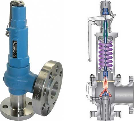
The basic spring loaded pressure Relief Valve has been developed to meet the need for a simple, reliable, system actuated device to provide overpressure protection.
The Valve consists of a Valve inlet or nozzle mounted on the pressurized system, a disc held against the nozzle to prevent flow under normal system operating conditions, a spring to hold the disc closed, and a body/Bonnet to contain the operating elements. The spring load is adjustable to vary the pressure at which the Valve will open.
When a pressure Relief Valve begins to lift, the spring force increases. Thus system pressure must increase if lift is to continue. For this reason pressure Relief Valves are allowed an overpressure allowance to reach full lift. This allowable overpressure is generally 10% for Valves on unfired systems. This margin is relatively small and some means must be provided to assist in the lift effort.
Most pressure Relief Valves, therefore, have a secondary control chamber or huddling chamber to enhance lift. As the disc begins to lift, fluid enters the control chamber exposing a larger area of the disc to system pressure.
This causes an incremental change in force which overcompensates for the increase in spring force and causes the Valve to open at a rapid rate. At the same time, the direction of the fluid flow is reversed and the momentum effect resulting from the change in flow direction further enhances lift. These effects combine to allow the Valve to achieve maximum lift and maximum flow within the allowable overpressure limits. Because of the larger disc area exposed to system pressure after the Valve achieves lift, the Valve will not close until system pressure has been reduced to some level below the set pressure. The design of the control chamber determines where the closing point will occur.
When superimposed back pressure is variable, a balanced bellows or balanced piston design is recommended. A typical balanced bellow is shown on the right. The bellows or piston is designed with an effective pressure area equal to the seat area of the disc. The Bonnet is vented to ensure that the pressure area of the bellows or piston will always be exposed to atmospheric pressure and to provide a telltale sign should the bellows or piston begin to leak. Variations in back pressure, therefore, will have no effect on set pressure. Back pressure may, however, affect flow.
A safety Valve is a pressure Relief Valve actuated by inlet static pressure and characterized by rapid opening or pop action. (It is normally used for steam and air services.)
A low-lift safety Valve is a safety Valve in which the disc lifts automatically such that the actual discharge area is determined by the position of the disc.
A full-lift safety Valve is a safety Valve in which the disc lifts automatically such that the actual discharge area is not determined by the position of the disc.
A Relief Valve is a pressure relief device actuated by inlet static pressure having a gradual lift generally proportional to the increase in pressure over opening pressure. It may be provided with an enclosed spring housing suitable for closed discharge system application and is primarily used for liquid service.
A safety Relief Valve is a pressure Relief Valve characterized by rapid opening or pop action, or by opening in proportion to the increase in pressure over the opening pressure, depending on the application and may be used either for liquid or compressible fluid.
A conventional safety Relief Valve is a pressure Relief Valve which has its spring housing vented to the discharge side of the Valve. The operational characteristics (opening pressure, closing pressure, and relieving capacity) are directly affected by changes of the back pressure on the Valve.
A balanced safety Relief Valve is a pressure Relief Valve which incorporates means of minimizing the effect of back pressure on the operational characteristics (opening pressure, closing pressure, and relieving capacity).
A pilotoperated pressure Relief Valve is a pressure Relief Valve in which the major relieving device is combined with and is controlled by a self-actuated auxiliary pressure Relief Valve.
A poweractuated pressure Relief Valve is a pressure Relief Valve in which the major relieving device is combined with and controlled by a device requiring an external source of energy.
A temperature-actuated pressure Relief Valve is a pressure Relief Valve which may be actuated by external or internal temperature or by pressure on the inlet side.
A vacuum Relief Valve is a pressure relief device designed to admit fluid to prevent an excessive internal vacuum; it is designed to reclose and prevent further flow of fluid after normal conditions have been restored.
Many Codes and Standards are published throughout the world which address the design and application of pressure Relief Valves. The most widely used and recognized of these is the ASME Boiler and Pressure Vessel Code, commonly called the ASME Code.
Most Codes and Standards are voluntary, which means that they are available for use by manufacturers and users and may be written into purchasing and construction specifications. The ASME Code is unique in the United States and Canada, having been adopted by the majority of state and provincial legislatures and mandated by law.
The ASME Code provides rules for the design and construction of pressure vessels. Various sections of the Code cover fired vessels, nuclear vessels, unfired vessels and additional subjects, such as welding and nondestructive examination. Vessels manufactured in accordance with the ASME Code are required to have overpressure protection. The type and design of allowable overpressure protection devices is spelled out in detail in the Code.
The following definitions are taken from DIN 3320 but it should be noted that many of the terms and associated definitions used are universal and appear in many other standards. Where commonly used terms are not defined in DIN 3320 then ASME PTC25.3 has been used as the source of reference. This list is not exhaustive and is intended as a guide only; it should not be used in place of the relevant current issue standard..
is the gauge pressure at which the lift is sufficient to discharge the predetermined flowing capacity. It is equal to the set pressure plus opening pressure difference.
is the cross sectional area upstream or downstream of the body seat calculated from the minimum diameter which is used to calculate the flow capacity without any deduction for obstructions.
is the calculated mass flow from an orifice having a cross sectional area equal to the flow area of the safety Valve without regard to flow losses of the Valve.
the pressure at which a Valve is set on a test rig using a test fluid at ambient temperature. This test pressure includes corrections for service conditions e.g. backpressure or high temperatures.
is that portion of the measured relieving capacity permitted by the applicable code or regulation to be used as a basis for the application of a pressure relieving device.
is the value of increasing static inlet pressure of a pressure Relief Valve at which there is a measurable lift, or at which the discharge becomes continuous as determined by seeing, feeling or hearing.
is the maximum allowable working pressure plus the accumulation as established by reference to the applicable codes for operating or fire contingencies.
Because cleanliness is essential to the satisfactory operation and tightness of a safety Valve, precautions should be taken during storage to keep out all foreign materials. Inlet and outlet protectors should remain in place until the Valve is ready to be installed in the system. Take care to keep the Valve inlet absolutely clean. It is recommended that the Valve be stored indoors in the original shipping container away from dirt and other forms of contamination.
Safety Valves must be handled carefully and never subjected to shocks. Rough handling may alter the pressure setting, deform Valve parts and adversely affect seat tightness and Valve performance.
When it is necessary to use a hoist, the chain or sling should be placed around the Valve body and Bonnet in a manner that will insure that the Valve is in a vertical position to facilitate installation.
Many Valves are damaged when first placed in service because of failure to clean the connection properly when installed. Before installation, flange faces or threaded connections on both the Valve inlet and the vessel and/or line on which the Valve is mounted must be thoroughly cleaned of all dirt and foreign material.
Because foreign materials that pass into and through safety Valves can damage the Valve, the systems on which the Valves are tested and finally installed must also be inspected and cleaned. New systems in particular are prone to contain foreign objects that inadvertently get trapped during construction and will destroy the seating surface when the Valve opens. The system should be thoroughly cleaned before the safety Valve is installed.
The gaskets used must be dimensionally correct for the specific flanges. The inside diameters must fully clear the safety Valve inlet and outlet openings so that the gasket does not restrict flow.
For flanged Valves, draw down all connection studs or bolts evenly to avoid possible distortion of the Valve body. For threaded Valves, do not apply a wrench to the Valve body. Use the hex flats provided on the inlet bushing.
Safety Valves are intended to open and close within a narrow pressure range. Valve installations require accurate design both as to inlet and discharge piping. Refer to International, National and Industry Standards for guidelines.
The Valve should be mounted vertically in an upright position either directly on a nozzle from the pressure vessel or on a short connection fitting that provides a direct, unobstructed flow between the vessel and the Valve. Installing a safety Valve in other than this recommended position will adversely affect its operation.
Discharge piping should be simple and direct. A "broken" connection near the Valve outlet is preferred wherever possible. All discharge piping should be run as direct as is practicable to the point of final release for disposal. The Valve must discharge to a safe disposal area. Discharge piping must be drained properly to prevent the accumulation of liquids on the downstream side of the safety Valve.
The weight of the discharge piping should be carried by a separate support and be properly braced to withstand reactive thrust forces when the Valve relieves. The Valve should also be supported to withstand any swaying or system vibrations.
If the Valve is discharging into a pressurized system be sure the Valve is a "balanced" design. Pressure on the discharge of an "unbalanced" design will adversely affect the Valve performance and set pressure.
The Bonnets of balanced bellows safety Valves must always be vented to ensure proper functioning of the Valve and to provide a telltale in the event of a bellows failure. Do not plug these open vents. When the fluid is flammable, toxic or corrosive, the Bonnet vent should be piped to a safe location.
It is important to remember that a pressure Relief Valve is a safety device employed to protect pressure vessels or systems from catastrophic failure. With this in mind, the application of pressure Relief Valves should be assigned only to fully trained personnel and be in strict compliance with rules provided by the governing codes and standards.
Pressure relief devices are used to provide a means of venting excess pressure which could rupture a boiler or pressure vessel. A pressure relief device is the last line of defense for safety. If all other safety devices or operating controls fail, the pressure relief device must be capable of venting excess pressure.
There are many types of pressure relief devices available for use in the boiler and pressure vessel industry. This inspector guide will address the most common devices found on boilers and pressure vessels. Virtually all jurisdictions require a pressure relief device to be manufactured and certified in accordance with the ASME BPV Code in addition to being capacity-certified by the National Board.
Safety Valve – This device is typically used for steam or vapor service. It operates automatically with a full-opening pop action and recloses when the pressure drops to a value consistent with the blowdown requirements prescribed by the applicable governing code or standard.
Relief Valve – This device is typically used for liquid service. It operates automatically by opening farther as the pressure increases beyond the initial opening pressure and recloses when the pressure drops below the opening pressure.
Safety Relief Valve – This device includes the operating characteristics of both a safety valve and a relief valve and may be used in either application.
Temperature and Pressure Safety Relief Valve – This device is typically used on potable water heaters. In addition to its pressure-relief function, it also includes a temperature-sensing element which causes the device to open at a predetermined temperature regardless of pressure. The set temperature on these devices is usually 210°F.
Rupture Disk– This device is classified as nonreclosing since the disk is destroyed upon actuation. This type of device may be found in use with a pressure vessel where a spring-loaded pressure relief device is inappropriate due to the operating conditions or environment.
The inlet piping connected to the device must not be smaller in diameter than the inlet opening of the device. An inlet pipe that is smaller than the device inlet opening could alter the operating characteristics for which the device was designed.
The discharge piping connected to the device must be no smaller than the discharge opening of the device. A discharge pipe that is smaller than the device discharge opening could cause pressure to develop on the discharge side of the device while operating.
Multiple devices discharging into a discharge manifold or header is a common practice. The discharge manifold or header must be sized so the cross-sectional area is equal to or greater than the sum of the discharge cross-sectional areas of all the devices connected to the discharge manifold or header. Failing this requirement, the devices would be subjected to pressure on the discharge side of the device while operating. Even a small amount of pressure here could adversely affect the operation of the device.
Constant leakage of the device can cause a build-up of scale or other solids around the discharge opening. This build-up can prevent the device from operating as designed.
Discharge piping connected to the device must be supported so as not to impart any loadings on the body of the device. These loadings could affect or prevent the proper operation of the device including proper reclosure after operating.
Some devices, especially on larger boilers, may have a discharge pipe arrangement which incorporates provisions for expansion as the boiler heats up or cools down. These expansion provisions must allow the full range of movement required to prevent loads being applied to the device body.
Drain holes in the device body and discharge piping, when applicable, must be open to allow drainage of liquids from over the device disk on spring loaded valves. Any liquid allowed to remain on top of the device disk can adversely affect the operating characteristics of the device.
Most jurisdictional requirements state the device must be "piped to a point of safe discharge." This must be accomplished while keeping the run of discharge piping as short as possible. Most jurisdictions also limit the number of 90 degree elbows that may be installed in the discharge piping. Too long of a run and multiple elbows can adversely affect the operation of the device.
While inspecting a boiler or pressure vessel, the inspector will also be evaluating the pressure relief device(s) installed on, or associated with, the equipment. The inspector should:
Compare the device nameplate set pressure with the boiler or pressure vessel maximum allowable working pressure (MAWP) and ensure the device set pressure does not exceed the MAWP. A device with a set pressure less than MAWP is acceptable. If multiple devices are used, at least one must have a set pressure equal to or less than the MAWP. The ASME Code should be reviewed for other conditions relating to the use of multiple devices.
Ensure the device still has the device manufacturer"s seals intact. These seals can be in the form of wire through a drilled hole with a soft metal button, such as lead, crimped on the wire, or removable parts may be stake punched or crimped to inhibit accidental movement. Any evidence of the seal mechanism being broken or destroyed could indicate tampering. If this is found, the inspector should require replacement of the device or repair by a qualified organization.
Instruct the owner or owner"s representative to lift the test lever, if so equipped, on spring-loaded devices. ASME BPV Code Section IV devices can have the test levers lifted without pressure in the boiler. All other devices must have at least 75% of the device set pressure under the device disk prior to lifting the test lever. If the device is found to be stuck in a closed position, the equipment should be immediately removed from service until such time the device can be replaced or repaired.
Lifting the test lever of a spring-loaded device may not be practical in all cases when inspecting pressure vessels. The contents of the vessel may be hazardous. In these cases, the vessel owner/user should have a testing procedure in place which will ensure documented inspection and testing of the device at regular intervals.
The small pressure relief devices found on many air compressor vessels have a ring inserted through a drilled hole on the end of the device stem. These are tested by pulling the stem straight out and then releasing. The discharge openings in this type of device are holes drilled around the periphery of the device. These holes often get filled with oily dust and grit which can cause eye damage when the device is tested. A rag, loosely wrapped around the device when testing, can help prevent personal injury from the dust and grit.
Additional information to aid inspections of pressure relief devices, including installation requirements, can be found in the following publications and sources:

As soon as mankind was able to boil water to create steam, the necessity of the safety device became evident. As long as 2000 years ago, the Chinese were using cauldrons with hinged lids to allow (relatively) safer production of steam. At the beginning of the 14th century, chemists used conical plugs and later, compressed springs to act as safety devices on pressurised vessels.
Early in the 19th century, boiler explosions on ships and locomotives frequently resulted from faulty safety devices, which led to the development of the first safety relief valves.
In 1848, Charles Retchie invented the accumulation chamber, which increases the compression surface within the safety valve allowing it to open rapidly within a narrow overpressure margin.
Today, most steam users are compelled by local health and safety regulations to ensure that their plant and processes incorporate safety devices and precautions, which ensure that dangerous conditions are prevented.
The principle type of device used to prevent overpressure in plant is the safety or safety relief valve. The safety valve operates by releasing a volume of fluid from within the plant when a predetermined maximum pressure is reached, thereby reducing the excess pressure in a safe manner. As the safety valve may be the only remaining device to prevent catastrophic failure under overpressure conditions, it is important that any such device is capable of operating at all times and under all possible conditions.
Safety valves should be installed wherever the maximum allowable working pressure (MAWP) of a system or pressure-containing vessel is likely to be exceeded. In steam systems, safety valves are typically used for boiler overpressure protection and other applications such as downstream of pressure reducing controls. Although their primary role is for safety, safety valves are also used in process operations to prevent product damage due to excess pressure. Pressure excess can be generated in a number of different situations, including:
The terms ‘safety valve’ and ‘safety relief valve’ are generic terms to describe many varieties of pressure relief devices that are designed to prevent excessive internal fluid pressure build-up. A wide range of different valves is available for many different applications and performance criteria.
In most national standards, specific definitions are given for the terms associated with safety and safety relief valves. There are several notable differences between the terminology used in the USA and Europe. One of the most important differences is that a valve referred to as a ‘safety valve’ in Europe is referred to as a ‘safety relief valve’ or ‘pressure relief valve’ in the USA. In addition, the term ‘safety valve’ in the USA generally refers specifically to the full-lift type of safety valve used in Europe.
Pressure relief valve- A spring-loaded pressure relief valve which is designed to open to relieve excess pressure and to reclose and prevent the further flow of fluid after normal conditions have been restored. It is characterised by a rapid-opening ‘pop’ action or by opening in a manner generally proportional to the increase in pressure over the opening pressure. It may be used for either compressible or incompressible fluids, depending on design, adjustment, or application.
Safety valves are primarily used with compressible gases and in particular for steam and air services. However, they can also be used for process type applications where they may be needed to protect the plant or to prevent spoilage of the product being processed.
Relief valve - A pressure relief device actuated by inlet static pressure having a gradual lift generally proportional to the increase in pressure over opening pressure.
Relief valves are commonly used in liquid systems, especially for lower capacities and thermal expansion duty. They can also be used on pumped systems as pressure overspill devices.
Safety relief valve - A pressure relief valve characterised by rapid opening or pop action, or by opening in proportion to the increase in pressure over the opening pressure, depending on the application, and which may be used either for liquid or compressible fluid.
In general, the safety relief valve will perform as a safety valve when used in a compressible gas system, but it will open in proportion to the overpressure when used in liquid systems, as would a relief valve.
Safety valve- A valve which automatically, without the assistance of any energy other than that of the fluid concerned, discharges a quantity of the fluid so as to prevent a predetermined safe pressure being exceeded, and which is designed to re-close and prevent further flow of fluid after normal pressure conditions of service have been restored.

A series of anomalies occurred in the boiler room that evening. The steel compression tank for the hydronic loop flooded, leaving no room for expansion. Water will expand at 3% of its volume when heated from room temperature to 180° F. When the burner fired, the expansion of the water increased the system pressure within the boiler. The malfunctioning operating control did not shut off the burner at the set point which caused the relief valve to open.
The brass relief valve discharge was installed with copper tubing piped solid to a 90° ell on the floor and the tubing further extended to the floor drain. The combination of hot water and steam from the boiler caused the discharge copper tubing to expand, using the relief valve as a fulcrum. The expansion of the copper discharge tubing pressing against the floor was enough to crack the brass relief valve, flooding the boiler room. The damage was not discovered until the next morning, several hours after the leak occurred. Thousands of dollars in damage was sustained and luckily no one was injured.
Each boiler requires some sort of pressure relieving device. They are referred to as either a safety, relief or safety relief valve. While these names are often thought of as interchangeable, there are subtle differences between them. According to the National Board of Boiler and Pressure Vessel Inspectors, the following are the definitions of each:
• Safety valve— This device is typically used for steam or vapor service. It operates automatically with a full-opening pop action and recloses when the pressure drops to a value consistent with the blowdown requirements prescribed by the applicable governing code or standard.
• Relief valve— This device is used for liquid service. It operates automatically by opening farther as the pressure increases beyond the initial opening pressure and recloses when the pressure drops below the opening pressure.
• Safety relief valve— This device includes the operating characteristics of both a safety valve and a relief valve and may be used in either application.
• Temperature and pressure safety relief valve— This device is typically used on potable water heaters. In addition to its pressure-relief function, it also includes a temperature-sensing element which causes the device to open at a predetermined temperature regardless of pressure. The set temperature on these devices is usually 210°.
• Relief valve piping— The boiler contractor installed a bushing on the outlet of the safety relief valve. Instead of 1 1/2-in. pipe, the installer used 3/4-in. pipe. When asked about it, he answered that he did not have any 1 1/2-in. pipe but had plenty of 3/4-in. pipe. I explained and then had to show the disbelieving contractor the code that states that the relief valve discharge piping has to be the same diameter as the relief valve outlet (see 2012 International Mechanical Code, 1006.6). By reducing the discharge pipe size, the relieving capacity of the safety valve may not be adequate to properly relieve the pressure inside the boiler, causing a dangerous situation.
The code also states that the discharge material shall be of rigid pipe that is approved for the temperature of the system. The inlet pipe size shall be full diameter of the pipe inlet for the relief valve. Some manufacturers suggest using black iron pipe rather than copper tubing. If using copper, it should have an air space that allows expansion should the relief valve open to avoid the accident that I referenced above. The discharge piping has to be supported and the weight of the piping should not be on the safety relief valve. Valves are not permitted in the inlet piping to or discharge piping from the relief valve. If you are using copper tubing on discharge piping, verify that there is room for expansion.
• Installation— Read the manufacturer’s installation manual as each may have different requirements. For instance, Conbraco requires that the discharge piping must terminate with a plain end and use a material that can handle temperatures of 375° or greater. This will preclude PVC or CPVC pipe for the discharge piping. The instruction manual for its model 12-14 steam relief valve stipulates that you cannot use a pipe wrench to install it. That would be good to know.
I once visited Boiler Utopia as the floor was clean and waxed. All the pipes were covered and exposed pipes were painted. There were large stickers detailing what was inside each pipe as well as directional arrows. Nothing was stacked next to the boilers. Yellow caution lines were painted on the floor around each boiler. I was in heaven. As I walked around the rear of the boiler, something clicked and triggered a warning bell. The discharge of the relief valve piping was about 6 in. from the floor but instead of a plain or angled cut end, the pipe had a threaded pipe cap on the termination. I asked the maintenance person about it and he said that the valve was leaking all over his newly waxed floor and this was the only way he could stop it. When I said that the discharge pipe should not have been threaded, he explained that it was not threaded and he had to take it to the local hardware store to thread it. I informed him that the cap had to be removed. We cut the pipe on an angle to prevent this.
• Steam boiler— Most manufacturers recommend a drip pan ell on the discharge of the steam boiler relief valve to eliminate the weight of the discharge piping on the relief valve. Some codes require the discharge to be vented outdoors.
• Testing— I will ask the attendees in my classes, “How often do you test the relief valves?” Most do not make eye contact and when I follow up with, “Why are they not tested?” I often hear that opening the relief valve will cause it to leak. I suggest that you refer to each manufacturer’s directions for testing. For instance, one will recommend once a year while another recommends twice a year. One manufacturer says, “Safety/relief valves should be operated only often enough to assure they are in good working order.” I am not sure what that even means. You want to also verify the proper test procedure as some will only want the relief valve tested when the boiler is at 75% of the rated pressure or higher of the relief valve.

Temperature/pressure-relief or TPR valves are safety devices installed on water heating appliances, such as boilers and domestic water supply heaters. TPRs are designed to automatically release water in the event that pressure or temperature in the water tank exceeds safe levels.
If temperature sensors and safety devices such as TPRs malfunction, water in the system may become superheated (exceed the boiling point). Once the tank ruptures and water is exposed to the atmosphere, it will expand into steam almost instantly and occupy approximately 1,600 times its original volume. This process can propel a heating tank like a rocket through multiple floors, causing personal injury and extensive property damage.
Water-heating appliance explosions are rare due to the fact that they require a simultaneous combination of unusual conditions and failure of redundant safety components. These conditions only result from extreme negligence and the use of outdated or malfunctioning equipment.
The TPR valve will activate if either water temperature (measured in degrees Fahrenheit) or pressure (measured in pounds per square inch [PSI]) exceed safe levels. The valve should be connected to a discharge pipe (also called a drain line) that runs down the length of the water heater tank. This pipe is responsible for routing hot water released from the TPR to a proper discharge location.
It is critical that discharge pipes meet the following requirements, which can be found in InterNACHI’s Water Heater Discharge Piping mini-course, at www.nachi.org/education. A discharge pipe should:
be constructed of an approved material, such as CPVC, copper, polyethylene, galvanized steel, polypropylene, or stainless steel. PVC and other non-approved plastics should not be used since they can easily melt.
be first piped to an indirect waste receptor such as a bucket through an air gap located in a heated area when discharging to the outdoors in areas subject to freezing, since freezing water could block the pipe.
discharge to a termination point that is readily observable by occupants, because discharge indicates that something is wrong, and to prevent unobserved termination capping.
A properly functioning TPR valve will eject a powerful jet of hot water from the discharge pipe when fully activated, not a gentle leak. A leaky TPR valve is an indication that it needs to be replaced. In the rare case that the TPR valve does activate, the homeowner should immediately shut off the water and contact a qualified plumber for assistance and repair.
Inspectors should recommend that homeowners test TPR valves monthly, although inspectors should never do this themselves. The inspector should demonstrate to the homeowner how the main water supply can be shut off, and explain that it can be located at the home"s main water supply valve, or at the water supply shut-off for the appliance on which the TPR is mounted.
The pressure at which a TPR valve will activate is printed on a data plate located beneath the test lever. This amount should not exceed the working pressure limit marked on the data plate of the water-heating appliance it serves.
TPR valves with missing data plates should be replaced.Although a TPR valve might never become activated, it is an essential safety component on boilers and domestic water heaters. Guidelines concerning these valves and their discharge pipes reflect real hazards that every homeowner and home inspector should take seriously. More information about this subject can be found in InterNACHI"s Water Heater Discharge Piping mini-course, InterNACHI"s Plumbing Inspection course or by contacting a qualified plumber.

Disclaimer: This Code of Ordinances and/or any other documents that appear on this site may not reflect the most current legislation adopted by the Municipality. American Legal Publishing Corporation provides these documents for informational purposes only. These documents should not be relied upon as the definitive authority for local legislation. Additionally, the formatting and pagination of the posted documents varies from the formatting and pagination of the official copy. The official printed copy of a Code of Ordinances should be consulted prior to any action being taken.
For further information regarding the official version of any of this Code of Ordinances or other documents posted on this site, please contact the Municipality directly or contact American Legal Publishing toll-free at 800-445-5588.
Finding a quality driving school in can be a difficult and time consuming task. driving-schools.com comprehensive database of driving schools helps you pick one that’s right for you.

Curtiss-Wright"s selection of Pressure Relief Valves comes from its outstanding product brands Farris and Target Rock. We endeavor to support the whole life cycle of a facility and continuously provide custom products and technologies. Boasting a reputation for producing high quality, durable products, our collection of Pressure Relief Valves is guaranteed to provide effective and reliable pressure relief.
While some basic components and activations in relieving pressure may differ between the specific types of relief valves, each aims to be 100% effective in keeping your equipment running safely. Our current range includes numerous valve types, from flanged to spring-loaded, threaded to wireless, pilot operated, and much more.
A pressure relief valve is a type of safety valve designed to control the pressure in a vessel. It protects the system and keeps the people operating the device safely in an overpressure event or equipment failure.
A pressure relief valve is designed to withstand a maximum allowable working pressure (MAWP). Once an overpressure event occurs in the system, the pressure relief valve detects pressure beyond its design"s specified capability. The pressure relief valve would then discharge the pressurized fluid or gas to flow from an auxiliary passage out of the system.
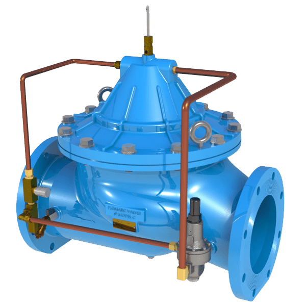
Below is an example of one of our pilot operated pressure relief valves in action; the cutaway demonstrates when high pressure is released from the system.
Air pressure relief valves can be applied to a variety of environments and equipment. Pressure relief valves are a safety valve used to keep equipment and the operators safe too. They"re instrumental in applications where proper pressure levels are vital for correct and safe operation. Such as oil and gas, power generation like central heating systems, and multi-phase applications in refining and chemical processing.
At Curtiss-Wright, we provide a range of different pressure relief valves based on two primary operations – spring-loaded and pilot operated. Spring-loaded valves can either be conventional spring-loaded or balanced spring-loaded.
Spring-loaded valves are programmed to open and close via a spring mechanism. They open when the pressure reaches an unacceptable level to release the material inside the vessel. It closes automatically when the pressure is released, and it returns to an average operating level. Spring-loaded safety valves rely on the closing force applied by a spring onto the main seating area. They can also be controlled in numerous ways, such as a remote, control panel, and computer program.
Pilot-operated relief valves operate by combining the primary relieving device (main valve) with self-actuated auxiliary pressure relief valves, also known as the pilot control. This pilot control dictates the opening and closing of the main valve and responds to system pressure. System pressure is fed from the inlet into and through the pilot control and ultimately into the main valve"s dome. In normal operating conditions, system pressure will prevent the main valve from opening.
The valves allow media to flow from an auxiliary passage and out of the system once absolute pressure is reached, whether it is a maximum or minimum level.
When the pressure is below the maximum amount, the pressure differential is slightly positive on the piston"s dome size, which keeps the main valve in the closed position. When system pressure rises and reaches the set point, the pilot will cut off flow to the dome, causing depressurization in the piston"s dome side. The pressure differential has reversed, and the piston will rise, opening the main valve, relieving pressure.
When the process pressure decreases to a specific pressure, the pilot closes, the dome is repressurized, and the main valve closes. The main difference between spring-loaded PRVs and pilot-operated is that a pilot-operated safety valve uses pressure to keep the valve closed.
Pilot-operated relief valves are controlled by hand and are typically opened often through a wheel or similar component. The user opens the valve when the gauge signifies that the system pressure is at an unsafe level; once the valve has opened and the pressure has been released, the operator can shut it by hand again.
Increasing pressure helps to maintain the pilot"s seal. Once the setpoint has been reached, the valve opens. This reduces leakage and fugitive emissions.
At set pressure the valve snaps to full lift. This can be quite violent on large pipes with significant pressure. The pressure has to drop below the set pressure in order for the piston to reseat.
The pilot is designed to open gradually, so that less of the system fluid is lost during each relief event. The piston lifts in proportion to the overpressure.
At Curtiss-Wright we also provide solutions for pressure relief valve monitoring. Historically, pressure relief valves have been difficult or impossible to monitor. Our SmartPRV features a 2600 Series pressure relief valve accessorized with a wireless position monitor that alerts plant operators during an overpressure event, including the time and duration.
There are many causes of overpressure, but the most common ones are typically blocked discharge in the system, gas blowby, and fire. Even proper inspection and maintenance will not eliminate the occurrence of leakages. An air pressure relief valve is the only way to ensure a safe environment for the device, its surroundings, and operators.
A PRV and PSV are interchangeable, but there is a difference between the two valves. A pressure release valve gradually opens when experiencing pressure, whereas a pressure safety valve opens suddenly when the pressure hits a certain level of over pressurization. Safety valves can be used manually and are typically used for a permanent shutdown. Air pressure relief valves are used for operational requirements, and they gently release the pressure before it hits the maximum high-pressure point and circulates it back into the system.
Pressure relief valves should be subject to an annual test, one per year. The operator is responsible for carrying out the test, which should be done using an air compressor. It’s imperative to ensure pressure relief valves maintain their effectiveness over time and are checked for signs of corrosion and loss of functionality. Air pressure relief valves should also be checked before their installation, after each fire event, and regularly as decided by the operators.
Direct-acting solenoid valves have a direct connection with the opening and closing armature, whereas pilot-operated valves use of the process fluid to assist in piloting the operation of the valve.
A control valve works by varying the rate of fluid passing through the valve itself. As the valve stem moves, it alters the size of the passage and increases, decreases or holds steady the flow. The opening and closing of the valve is altered whenever the controlled process parameter does not reach the set point.
Control valves are usually at floor level or easily accessible via platforms. They are also located on the same equipment or pipeline as the measurement and downstream or flow measurements.
An industrial relief valve is designed to control or limit surges of pressure in a system, most often in fluid or compressed air system valves. It does so as a form of protection for the system and defending against instrument or equipment failure. They are usually present in clean water industries.
A PRV is often referred to as a pressure relief valve, which is also known as a PSV or pressure safety valve. They are used interchangeably throughout the industry depending on company standards.

This website is using a security service to protect itself from online attacks. The action you just performed triggered the security solution. There are several actions that could trigger this block including submitting a certain word or phrase, a SQL command or malformed data.


 8613371530291