
crosby safety valve quotation
Crosby pressure relief valves have been on the forefront of overpressure protection for more than 140 years. The direct spring-operated safety and pressure relief valves are among the world’s most widely used in oil and gas production and refining, petrochemical and chemical processing, and conventional and nuclear power industries. Crosby pressure relief valves uphold the industry’s most extensive and capable flow facilities for testing gas, liquid, steam and multi-phase applications.
Crosby is part of Emerson’s pressure relief portfolio, a complete range of standard and customized solutions, whatever need you have for overpressure protection.
Emerson is an industry leader in pressure relief valve technology. A single point provider, they offer an extensive product range for reliable performance with lower valve life-cycle costs and unique solutions. Their unrivaled engineering and technical expertise results in pressure management products, application solutions and services that can positively affect your business, safety, operations and the bottom line. Their engineering teams have designed testing equipment and procedures that assure optimum valve performances under all service conditions.
Facilities have cryogenic flow testing capabilities down to -320°F / -196°C, and flow steam testing, making them amongst the largest in the world that are used for research, experimentation and control of emissions on relief valves, like Crosby’s.
Crosby’s H-Series direct spring-operated safety valves are the trusted and proven solution to thorough overpressure protection for steam safety applications such as economizers, steam drums, superheaters, reheaters and more.
Crosby’s J-Series valves provide high quality and dependable overpressure protection for air, gas, steam, vapor, liquid and two-phase applications in one simple design.
Crosby leads the way in pressure relief valve technology. Explore high quality and dependable overpressure protection and phase applications in their catalog of relief valves.
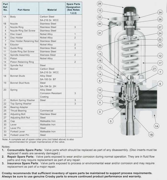
Large orifice closed bonnet pressure relief valves. Also available with open bonnet as Styles HS/HSU; and as large orifice pilot operated pressure relief valves. Style JPV-A, for air, gas and steam. Ask for Catalog No. 307. Specifications:
A unique, completely sealed pressure relief valve for transportation and storage of chlorine and other toxic and corrosive fluids. Ask for Catalog No. 306. Specifications:
A sanitary pressure/vacuum pressure relief valve for the beverage, food processing and pharmaceutical industries. This valve provides three modes of self actuated operation:
Non-flowing, snap-acting, pilot operated, pressure relief valves. High performance valves for overpressure protection of pipes and vessels containg gases and vapors. Ask for Catalog No. 318. Specifications:
Non-flowing, modulating, pilot operated, pressure relief valve. Used for overpressure protection of gas, vapor, liquid and steam. Mounted on the same main valve used with Style JPV. Ask for Catalog No. 318. Specifications:
Non-flowing, modulating, pilot operated, pressure relief valve. Used for overpressure protection of high temperature fluids including hydrocarbons, inert gases and steam. Ask for Catalog No. 318. Specifications:
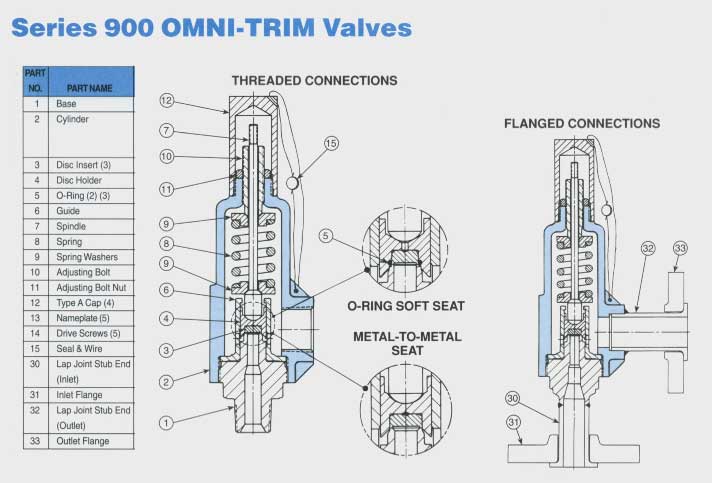
Pressure relief valve with single trim for liquid, gas and steam service. Precision lapped flat metal to metal seats or elastomer and TFE O-ring soft seats provide the ultimate in seat tightness. Blowdown is typically less than 20%. Capacities certified by National Board of Boiler and Pressure Vessel Inspectors. Ask for Catalog No. 902. Specifications:
Series 800 pressure relief valves are designed for use on air, gas, vapor and steam service. External precise blowdown control provides shorter blowdown then the Series 900, typically in the range of 5 to 15 percent. Capacities certified by National Board of Boiler and Pressure Vessel Inspectors. Ask for Catalog No. 902. Specifications:
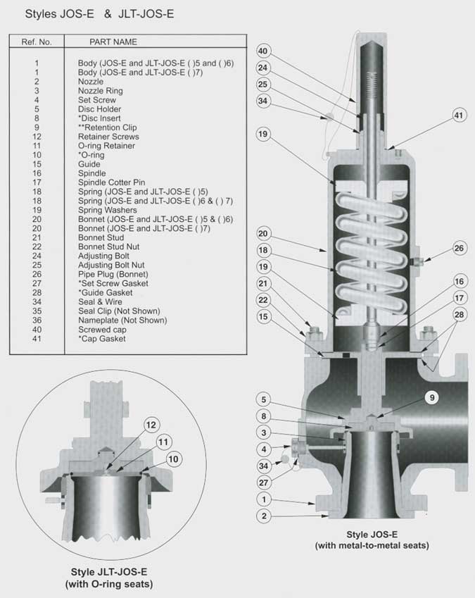
Nozzle type safety valve for saturated and superheated steam service. Seat tightness up to 95% of valve set pressure. Ask for Catalog No. 408. Specifications:
Protect superheaters from overheating during startup, prolong the life and reduce maintenace of safety valves. Ask for Catalog No. 403. Specifications:

On the 27th of May, 1879, the Consolidated Safely-Valve Company, a Connecticut corporation, brought a suit in equity in the circuit court of the United States for the district of Massachusetts, against the Crosby Steam-Gage & Valve Company, a Massachusetts corporation, for the infringement of letters patent No. 58,294, granted to George W. Richardson, September 25, 1866, for an improvement in steam safety-valves. The claim of that patent was as follows: "What I claim as my improvement, and desire to secure by letters patent, is a safety-valve with the circular or annular flange or lip, c, c, constructed in the manner, or substantially in the manner, shown, so as to operate as and for the purpose herein described." On the 2d of June, 1879, the same plaintiff brought a suit in equity in the same court against the same defendant, for the infringement of letters patent No. 85,963, granted to the same George W. Richardson, January 19, 1869, for an improvement in safety-valves for steam-boilers or generators. The claim of that patent was as follows: "What I claim as new, and desire to secure by letters patent, is the combination of the surface beyond the seat of the safety-valve, with the means herein described for regulating or adjusting the area of the passage for the escape of steam, substantially as and for the purpose described."
In the answers in the two suits, the defense of want of novelty was set up, and alleged anticipating patents were referred to; infringement was denied; and it was averred that the valves made and sold by the defendant were the inventions of George H. Crosby, and were described in two patents granted to him and owned by the defendant,—one, No. 159,157, dated January 26, 1875; and the other, No. 160,167, dated February 23, 1875. The same proofs were taken in the two suits, and they were heard together in the circuit court; in each suit a decree was made dismissing the bill, (7 Fed. Rep. 768;) and from each decree the plaintiff appealed to this court. Non-infringement was found by the circuit court. This court (113 U. S. 157, 5 Sup. Ct. Rep. 513) reversed the decree in each case, and directed the circuit court to enter a decree in each case, sustaining the validity of the patent, decreeing infringement, and awarding an account of profits and damages. On receiving the mandate of this court in the suit on the patent of 1866, the circuit court, on the 18th of May, 1885, entered a decree in conformity therewith, and for a recovery by the plaintiff of profits and damages from February 15, 1879, and ordered a reference to a master to take an account of such profits and damages. A like decree was made on the mandate in the suit on the patent of 1869. The date of February 15, 1879, was taken because that was the time when the title to each of the patents became vested in the plaintiff.
The master took voluminous proofs, and filed his report on the 5th of August, 1889, covering both of the suits. The report of the master found that the total profits which the defendant had derived from its manufacture and sale of steam safety-valves containing the improvement described and claimed in the patent of 1866, from February 15, 1879, to September 25, 1883, the date of the expiration of the patent, amounted to $40,344.59. Both parties filed exceptions to the report; and on the 11th of October, 1890, the circuit court entered a decree overruling both sets of exceptions and awarding to the plaintiff a recovery for the $40,344.59, with interest thereon from August 5, 1889, the date of the filing of the master"s report, and the costs of the suit. From this decree the defendant has appealed. The opinion of the circuit court is reported in 44 Fed. Rep. 66.
The master says, in his report in the case, in respect to the patent of 1866, which he calls No. 1,184, that, for the period from February 15, 1879, to September 25, 1883, he attributes the entire commercial value of the valves manufactured and sold by the defendant to the improvement covered by the patent of 1866. He adds: "Richardson"s invention, as described and claimed in that patent, revolutionized the are of relieving steam-boilers from steam pressure rapidly approaching the dangerous point. It made effective for that purpose—rapidly and with comparatively small loss of steam—apparatus described in other patents, which very nearly embodied Richardson"s invention, but did not actually contain it. The supreme court in these cases has defined this invention, and has declared it to be a vital one—a life-giving principle to structures very nearly approaching, but not quite containing an embodiment of, Richardson"s discovery." The master also says in his report: "It was contended before me that none of the complainants" valves of commerce contained this invention of Richardson, but, upon the whole evidence, with specimens of all the different valves put on the market by the complainants before me, I find that they all contained Richardson"s improvement of 1866. The supreme court has decided in these cases that the defendants" valves contain this invention, and it is under this decision that the accounting in No. 1,184 is before me. Eliminate this invention from the defendants" valves, and they would be commercially worthless. No substitute for this invention has been suggested to me, and I know of none which the defendants could have used its place to have made their valves of commercial value. The defendants claim that some of the profits which they have made are due to the peculiar form of their valves, but the form which they used in making their valves was the form in which they clothed the Richardson invention, the life of their valves, and without that life the Crosby form is worthless."
The specifications and drawings of the two patents of Richardson are set forth at length in the report of the cases in 113 U. S. 157, 5 Sup. Ct. Rep. 513. The opinion of this court said, (page 178, 113 U. S., and page 525, 5 Sup. Ct. Rep:) "There is one structural difference between the two valves, which is now to be mentioned. In the Richardson valve, all the steam which escapes into the open air escapes from the huddling chamber, through a stricture which is smaller than the aperture at the ground joint. In the defendants" valve, the valve proper has two ground joints, one at the inner periphery of the annulus and the other at its outer periphery, and only a part of the steam, namely, that which passes through one of the ground joints, passes into the huddling chamber and then through the stricture, the other part of the steam passing directly from the boiler into the air, through the other ground joint. But all of that part of the steam which passes into the huddling chamber, and under the extended surface, passes through the constriction at the extremity of such chamber, in both valves, the difference being one only of degree, but with the same mode of operation." In respect to this point, one of the briefs for the appellant, now submitted, says: "The appellant"s valve in this case, known as the "Crosby Valve," and made in accordance with the Crosby patents, is so constructed that it has two ground joints. When the valve rises by reason of increased pressure, part of the steam escapes through one ground joint directly into the open air, and part of the steam escapes through the other ground joint into a huddling chamber, and thence into the air through orifices which form an aperture less than the ground joint orifice through which it enters said huddling chamber. Although the relief to the boiler caused by the blowing off of the valve was, in consequence of this double mode of escape for the steam, due to the combined effect of its escape through the huddling chamber and its escape through the second ground joint, yet, as all that part of the steam which entered the huddling chamber passed through the strictured opening, the court held that the valve contained the Richardson device, and was therefore an infringement." The master further says in his report: "The defendants claimed before me that the complainants, in the accounting in 1,184, which relates only to the Richardson patent of 1866, should prove specifically the value of the invention secured to them under that patent as used by the defendants, and that, as it was claimed by complainants (and the supreme court has so decided) that defendants used also Richardson"s invention of 1869, to value of the invention secured to the complainants by the 1869 patent must be determined, and not made an element in the recovery to be had under the accounting in 1,184. I have no means of determining the value of that invention as used by the defendants from February 15, 1879, to September 25, 1883, or of stating in dollars and cents how much of the profits of the defendants during that period is due to that invention. The complainants claimed that during that period all the profits of the defendants were due to the Richardson invention of 1866, and, as the Richardson invention of 1869 belonged also to the complainants, and as the complainants and defendants were respectively the same in each case,—1,184 relating to the said invention of 1866, and 1,199 relating to the invention of 1869, and as the said period from February 15, 1879, to September 25, 1883, was included within the period to be covered by the accounting in each case, no injustice is done the defendants in acceding to the complainants" claim in this regard; and this is especially so in view of the fact that the defendants claimed that the adjustable device as shown in the Richardson patent of 1869 is worthless as such, and that the cost of the Crosby valve is less without the said so-called "adjustable ring" and is a better and more useful safety appliance." The master also found that the plaintiff had suffered no damages in addition to the profits to be assessed against the defendant, in regard to the patent of 1866.
The defendant"s exceptions to the master"s report cover the following points: (1) The disallowance to the defendant of the sum of $1,978.34; (2) the finding that the Richardson valve sold by the plaintiff contained the invention set forth in the patent of 1866; (3) the finding that the entire commercial value of the valves made and sold by the defendant between February 15, 1879, and September 25, 1883, was due to the improvement covered by the patent of 1866; (4) the failure to find that the plaintiff was entitled to recover only for the ascertained value of the improvements covered by the two patents over and above the value of previous safety-valves known to the art and open to be used by the defendant; (5) the failure to require the plaintiff to show what in fact was the value attributable to the improvement of 1866; (6) the failure to require the plaintiff to show what was the value of the improvement of 1866, in comparison with the value of safety-valves previously known to the art and free to the defendant to be used; (7) the failure to find that the defendant was liable to account to the plaintiff for only a nominal sum; (8) to the same purport as exception 7; (9) the failure to ascertain what part of the profits of the defendant was due to the two patented improvements of Crosby; and (10) the failure to ascertain what part of the profits was due to the employment of the improvement covered by the patent of 1869.
The circuit court; held by Judge COLT, says in its opinion: "In judging of the correctness of the method pursued by the master in his estimation of defendants" profits, the construction put upon the Richardson 1866 patent, and the language used in respect thereto, as embodied in the opinion of the supreme court, cannot be disregarded. It was clearly the duty of the master in his findings, as it is also the duty of the court at the present time, to give full force and effect to the opinion of the supreme court. If the contention of the defendants is sound, that the supreme court, in their interpretation of the Richardson 1866 patent, gave too much prominence to the feature known as the "huddling chamber with a strictured orifice," it is for them, upon appeal, to obtain some modification of that opinion; but so long as it stands as the opinion of that court, the views therein expressed should be strictly carried out. The position, therefore, taken by the defendants, that the complainants are only entitled to nominal damages, because, as they say, the Richardson valve of commerce does not contain the huddling chamber with a strictured orifice, or, in other words, a huddling chamber with an aperture for the exit of the steam into the open air which is of smaller area than the aperture at the ground joint, I cannot regard as sound in view the opinion of the supreme court. That court construed the Richardson patents, and it held that defendants" valve was within those patents, and it gave a broad construction to the Richardson 1866 patent." The opinion then says that the court approves and adopts the conclusions reached by the master in the paragraphs before quoted from his report. In the former opinion of this court, at 113 U. S. 170, 5 Sup. Ct. Rep. 520, it was said: "In the present case the defendant has introduced in evidence the before-named English patents to Ritchie, Webster, and Hartley, and the English patent to William Naylor, No. 1,830, granted July 1, 1863; and also letters patent of the United States, No. 10,243, granted to Henry Waterman, November 15, 1853, and the reissue of the same, No. 2,675, granted to him July 9, 1867. In view of all these patents, and of the state of the art, it appears that Richardson was the first person who described and introduced into use a safety-valve which, while it automatically relieved the pressure of steam in the boiler, did not, in effecting that result, reduce the pressure to such an extent as to make the use of the relieving apparatus practically impossible, because of the expenditure of time and fuel necessary to bring up the steam again to the proper working standard. His valve, while it automatically gives relief before the pressure becomes dangerously great, according to the point at which the valve is set to blow off, operates so as to automatically arrest with promptness the reduction of pressure when the boiler is relieved. His patent of 1866 gave a moderate range of pressure, as the result of the proportions there specified, and his patent of 1869 furnished a means of regulating that range of pressure, by a screw-ring, within those narrow limits which are essential in the use of so subtle an agent as steam. In regard to all the above patents adduced against Richardson"s patent of 1866, it may be generally said that they never were, in their day, and before the date of that patent, or of Richardson"s invention, known or recognized as producing any such result as his apparatus of that patent produces, as above defined. Likenesses in them, in physical structure, to the apparatus of Richardson, in important particulars, may be pointed out, but it is only as the anatomy of a corpse resembles that of the living being. The prior structures never effected the kind of result attained by Richardson"s apparatus, because they lacked the thing which gave success. They did not have the retarding stricture which gave the lifting opportunity to the huddled steam, combined with the quick falling of the valve after relief had come. Taught by Richardson, and by the use of his apparatus, it is not difficult for skilled mechanics to take the prior structures, and so arrange and use them as to produce more or less of the beneficial results first made known by Richardson; but, prior to 1866, though these old patents and their descriptions were accessible, no valve was made producing any such results. Richardson"s patent of 1866 states that the addition to the head of the valve terminates in an annular lip, which fits loosely around the valve-seat, and is separated from it by about 1-64 of an inch for an ordinary spring, and a less space for a strong spring, and a greater space for a weak spring, forming an annular chamber, and regulating the escape of the steam; that the steam, when the valve is lifted, passes beyond the valve-seat, and into the annular chamber, and acts against the increased surface of the valve-head, and thus overcomes the increasing resistance of the spring due to its compression, and lifts the valve higher, and the steam escapes freely into the open air, until the pressure is sufficiently reduced, when the spring immediately closes the valve. It is not shown that, before 1866, any known valve produced this result."
The opinion also said: "It appears to have been easy enough to make a safety-valve which would relieve the boiler, but the problem was to make one which, while it opened with increasing power in the steam against the increasing resistance of a spring, would close suddenly, and not gradually, by the pressure of the same spring against the steam. This was a problem of the reconciliation of antagonisms, which so often occurs in mechanics, and without which practically successful results are not attained. What was needed was a narrow stricture to hold back the escaping steam, and secure its expansive force inside of the lip, and thus aid the direct pressure of the steam from the boiler in lifting the valve against the increasing tension of the spring, with the result that, after only a small, but a sufficient, reduction in the boiler pressure, the compressed spring would, by its very compression, obtain the mastery and close the valve quickly. This problem was solved by Richardson, and never before. His patent of 1869 describes the arrangement and operation of the whole apparatus, with the adjustable ring, thus: "When the pressure of the steam lifts the valve, the steam acts against the surface of an annular space between the bevel of the valve-seat and the downward projecting flange of the cap-plate, to assist in holding up the valve against the increasing resistance of the spring. The aperture between the valve and its seat is always greater than that between the flange and the upward-projecting rim, and thus the steam in the annular space assists in holding up the valve till the boiler pressure falls below that at which the valve opened. The difference between the closing pressure and the opening pressure depends on the distance between the flange and the rim. There is a central aperture in the cap, through which the steam escapes when the valve is lifted, which is surrounded by a projecting cylindrical flange, threaded on the outside, to which is fitted a threaded ring, which can be turned up or down and secured by a set-screw. By this means, the area of the aperture for the escape of steam beyond the valve-seat is adjustable, the space being largest when the ring is down and smallest when the ring is up."
The opinion then considers the prior patents of Ritchie, Webster, and Hartley, and holds that they did not anticipate Richardson"s invention of 1866. In regard to the Webster patent it says: "The Webster patent shows a huddling chamber and a stricture. But the evidence shows that valves made with the proportions shown in the drawing of Webster work with so large a loss of boiler pressure, before closing, as to be practically and economically worthless. Webster"s patent describes a means of making the area for the escape of steam adjustable, consisting in adjusting up and down, on a smooth valve-stem, a sliding collar or flange, and fixing it in place by a set-screw. But it does not show the screw-ring of Richardson, with its minute delicacy of adjustment and action." Further it says: "Richardson is therefore entited to cover, by the claim of his patent of 1866, under the language, "a safety-valve with the circular or annular flange or lip, c, c, constructed in the manner, or substantially in the manner, shown, so as to operate as and for the purpose herein described," a valve in which are combined an initial area, an additional area, a huddling chamber beneath the additional area, and a strictured orifice leading from the huddling chamber to the open air, the orifice being proportioned to the strength of the spring, as directed. The direction given in the patent is that the flange or lip is to be separated from the valve-seat by about 1-64 of an inch for an ordinary spring, with less space for a strong spring, and more space for a weak spring, to regulate the escape of the steam, as required." "The Richardson patents have a disk valve, an annular huddling chamber, an annular stricture at the outer extremity of the radii from the center of the valve, an additional area which is radially beyond the disk valve, and a cylindrical steam way. But, before 1866, an annular form of safety-valve was well known. Such a valve necessarily requires an annular steam way. In the defendant"s valve, (complainant"s Exhibit A,) the same effects, in operation, are produced as in the Richardson valve, by the means described in Richardson"s claims. In both structures the valve is held to its seat by a spring, so compressed as to keep the valve there until the pressure inside of the boiler is sufficient to move the valve against the pressure of the spring, so that the steam escapes through the ground joint into a chamber covered by an extension of the valve, in which chamber the steam acts expansively against the extended surface, and increases the pressure in opposition to the increasing pressure of the spring, and assists in opening the valve wider; this chamber, in the defendant"s valve, has, at its termination, substantially the same construction as Richardson"s valve, namely, a stricture which causes the steam to act, by expansive force, against the extended surface of the valve; and in both valves, after the pressure of the steam has been somewhat reduced in the boiler, the closing movement is quickened, as the valve nears its seat, in consequence of the reduced pressure of the steam on the extended surface, and the valve comes suddenly to its seat. In the Richardson valve, the valve proper is a disk, and the extended surface is an annulus surrounding the disk, while, in the defendant"s valve, the valve proper is an annulus, and the extended surface is a disk inside of the annulus. But this is a mere interchange of form between the valve proper and the extended surface, within the skill of an ordinary mechanic."
It is contended by the defendant that the proof shows that a valve made in the required proportions of the patent of 1866, and in accordance with its drawing and description, without the improvement of 1869, and with the area of escape at the outlet smaller than the area of entrance at the ground joint, is not as economical or as good in action as the earlier Webster valve; that a valve constructed in accordance with the patent of 1866 is not an economical valve, but operates with a large loss of steam; that the valves sold by the plaintiff as Richardson valves, being the same in pattern as those sold by it since it began business, are not constructed so that the area of escape from the huddling chamber is smaller than the area of entrance from the ground joint, but, on the contrary, it is about twice as large; and that the plaintiff has never put a valve on the market with the orifice of escape from the huddling chamber smaller than the orifice of entrance in to that chamber. We see no reason in the record for disturbing the conclusions of the master and the circuit court, that the entire commercial value of the valves made and sold by the defendant was due to the improvement covered by the patent of 1866, and that the plaintiff"s valves of commerce all of them contain the improvements covered by the patent of 1866. Moreover, the master reports profits only, and finds that the plaintiff has suffered no damages in addition to the profits to be assessed against the defendant. If there had been an award of damages, and the loss of trade by the plaintiff, in consequence of the competition by the defendant, had been an element entering into those damages, it would have been a material fact to be shown by the plaintiff that it was putting on the market goods embodying the Richardson invention; but, as the plaintiff recovers only the profits made by the defendant in using in its business the Richardson invention, it is immaterial whether or not the plaintiff itself employed that invention. The profits made by the defendant cannot be increased or diminished by any act on the part of the plaintiff; and the amount of them is not affected by the question whether during the same time the plaintiff did or did not use the patented invention.
In regard to the holding by the master and the court that all the profits of the defendant from the valves it made and sold were to be attributed to the employment by it of the improvement covered by the patent of 1866, we hold that, in view of what was determined in the former opinion of this court, and on the whole case, the safety-valves known to the art and open to be used by the defendant would not do the same work as the Richardson invention covered by the patent of 1866, or have any commercial value; and that, within the case of Garretson v. Clark, 111 U. S. 120, 4 Sup. Ct. Rep. 291, it appears, by reliable and satisfactory evidence, that the profits made by the defendant are to be calculated in reference to the entire valve made and sold by it, for the reason that the entire value of that valve, as a marketable article, is properly and legally attributable to the patented feature of the patent of 1866.
As to the assignment of error that the master did not ascertain what part of the profits derived by the defendant was due to the patented improvements covered by the two patents to Crosby, the master said, in his report, as before quoted: "The defendants claim that some of the profits which they have made are due to the peculiar form of their valves, but the form which they used in making their valves was the form in which they clothed the Richardson invention, the life of their valve, and without that life the Crosby form is worthless." The defendant contends that the master ought to have found, upon the evidence, that, with the exception of an allowance of a nominal sum for profits on account of the Richardson invention, the profits of the defendant accrued from its employment of the Crosby inventions. This contention was made before the master, and was overruled by him. There was some evidence before the master relating to the form of the Crosby valve, to the effect that it had an encased spring, and was readily attached and adjusted, and that those features of its construction were advantageous. The first patent to Crosby does not show any encased spring; and, while the second patent to him shows an encased spring, its claims relate solely to the features which produce and regulate the recoil action of the steam. The master was correct, therefore, in saying that the patented improvements of Crosby embodied the form in which the defendant clothed the Richardson invention, the life of the defendant"s valve, and without which the Crosby form was worthless. There is no evidence that any of the things patented by Crosby gave any advantage in selling the defendant"s valve. It appearing that the defendant"s valve derived its entire value from the use of the Richardson invention covered by the patent of 1866, and that the entire value of the defendant"s valve, as a marketable article, was properly and legally attributable in that invention of Richardson, the plaintiff is entitled to recover the entire profit of the manufacture and sale of the valves. Elizabeth v. Pavement Co., 97 U. S. 126, 139; Root v. Railway Co., 105 U. S. 189, 203; Garretson v. Clark, 111 U. S. 120, 4 Sup. Ct. Rep. 291; Callaghan v. Myers, 128 U. S. 617, 665, 666, 9 Sup. Ct. Rep. 177; Hurlbut v. Schillinger, 130 U. S. 456, 471, 472, 9 Sup. Ct. Rep. 584.
The defendant contends that the master and the circuit court erred in disallowing as a credit to the defendant, in diminution of the profits reported, the sum of $1,978.34, it being contended that that was an expense suffered by the defendant in modifying and reconstructing certain valves to render them more perfect and more salable. These were valves made by the defendant, and destroyed by it before sale, or after a sale and an exchange for other valves; which destroyed valves did not appear in the account on either side, thus becoming unsold valves. The expense thus referred to is one incurred in making experimental and defective valves. In regard to this item, the master said in his report: "Item 7 is for modification and reconstruction of iron valves. The costs of the reconstructed valves have already been charged in the costs of valves for the periods in which the "reconstruction," so called, took place. The old valves were destroyed, and a salvage made of such parts as were of value or could be* used and new valves were made, and their full costs charged in the accounts of defendants. This item 7 is a claim for the cost of the destroyed valves, (whether with or without an allowance for salvage I am unable to say,) and should not be allowed." In respect to this item, the defendant put in the following claim before the master: "Finding 8. The charge found in item 7, in heading IV. of defendants" account filed with the master, is for the reconstruction and modification of safety-valves made by them. The work of this modification and reconstruction was in the direction of perfecting the characteristics of the safety-valves they were then producing. The result of such endeavor was that they produced a species of safety-valves, classified in the account as iron safety-valves, which was made and sold after that time by the defendants, the account of which has been fully rendered to the master, and on which he has computed profits in his consideration of them. In the labor and efforts of the defendants certain valves were rendered useless, and were valueless except for junk, and certain parts of valves made for them and paid for were rejected, and the difference between the original cost and their value as old metal became a loss to the defendants. All these losses occasioned by the destruction of valves, by the replacing of valves in the hands of buyers of valves by giving them new valves for old ones without additional charge, and by the destruction of parts of valves which could not be used because of the modification of the design, were a part of the expense suffered by the defendants in their valve business, in the producing and manufacture of a marketable safety-valve of the characteristics of the Crosby valve, and constituted a wastage in their business which their valve department suffered for the purpose of making more salable products. This loss was an item of expense which should be charged to the cost of valves as such, because it became a charge upon all the safety-valves thereafter made following the plan and models which resulted from such loss. Upon inspection of the records of the master, the defendants do not find that they have filed specifications of such loss, and, trusting to the belief that their account, with the testimony, was sufficient and proper in such respect, they evidently neglected so to do. Moreover, the examination of Mr. Crosby, the defendants" superintendent at that time, by the complainants, upon that item of their account, shows only the items of loss in part. This latter incomplete showing, which is now first noticed by the defendants, was evidently overlooked, and thus the facts making up the character of the loss were not properly and fully laid before the master for his consideration. On this account the defendants respectfully submit a statement of facts, and request that they may introduce testimony, if necessary, in proof thereof." Here follows the statement: "Whenever valves have been accounted for as returned, and the master has deducted the returned valves from the sales and costs, the account then shows itself free from any profits on such valves. The cost to the defendants of such valves remains as a part of the expenses they have incurred in the making of valves, and which, when they were destroyed, became a direct loss to them and their business. It is for this actual loss so sustained, decreasing their profits, which they now ask to have damages allowed. The loss is inseparable from their whole valve business, and belongs to it."
To this view, the master replied as follows, in his report: "It is clear, upon this statement, that no allowance should be made to defendants for the sixty-nine valves which they made and destroyed without selling or consigning them. The thirty-eight valves which were originally sold to Babcock & Wilcox were accounted for both in costs and sales, but, when new valves were sent them to replace the returned valves, the new valves were not included in defendants" accounts, either in costs or sales. The twelve brass valves were returned and so treated in the account. The result, therefore, is substantially this: that the defendants made some one hundred and nineteen valves, which they subsequently destroyed, with some castings which they concluded not to use. I find no sufficient reasons for modifying my former disallowance of item 7 in each case." In regard to this item, the circuit court said: "As for the objection to the findings of the master respecting expenses to be allowed for certain valves destroyed, which forms the subject-matter of the first exception, I think the master was right in the conclusion he reached. The defendants were not charged on valves which were subsequently destroyed, or, if so, they were not charged upon the new valves which replaced them. See master"s note 29, page 43 of master"s report. The master properly disallowed the cost of destroyed valves." Without going into details, it is sufficient to say that we concur in the conclusion that the defendant was not charged for valves which were subsequently destroyed, or, if so, it was not charged upon the new valves which replaced the destroyed valves.
As for the contention that the destroyed valves ought to form a credit against the profits actually realized by the defendant on other valves, it is sufficient to say that the only subject of inquiry is the profit made by the defendant on the articles which it sold at a profit, and for which it received payment, and that losses incurred by the defendant through its wrongful invasion of the patent are not chargeable to the plaintiff, nor can their amount be deducted from the compensation which the plaintiff is entitled to receive. The Cawood Patent, 94 U. S. 695; Elizabeth v. Pavement Co., 97 U. S. 126, 138; Tilghman v. Proctor, 125 U. S. 136, 8 Sup. Ct. Rep. 894.
"A safety valve with the circular or annular flange or lip c c, constructed in the manner, or substantially in the manner, shown, so as to operate as and for the purpose herein described,"
the patentee is entitled to cover a valve in which are combined an initial area, an additional area, a huddling chamber beneath the additional area, and a strictured orifice leading from the huddling chamber to the open air, the orifice being proportioned to the strength of the spring, as directed.
Richardson was the first person who made a safety valve which, while it automatically relieved the pressure of steam in the boiler, did not, in effecting
His valve was the first which had the strictured orifice to retard the escape of the steam and enable the valve to open with increasing power against the spring and close suddenly, with small loss of pressure in the boiler.
The direction given in the patent that the flange or lip is to be separated from the valve seat by about one sixty-fourth of an inch for an ordinary spring, with less space for a strong spring and more space for a weak spring, to regulate the escape of steam as required, is a sufficient description as matter of law, and it is not shown to be insufficient as a matter of fact.
Letters patent No. 85,963, granted to said Richardson January 19, 1869, for an improvement in safety valves for steam boilers or generators, are valid.
"The combination of the surface beyond the seat of the safety valve, with the means herein described for regulating or adjusting the area of the passage for the escape of steam, substantially as and for the purpose described,"
The patents of Richardson are infringed by a valve which produces the same effects in operation by the means described in Richardson"s claims, although the valve proper is an annulus and the extended surface is a disc inside of the annulus, the Richardson valve proper being a disc and the extended surface an annulus surrounding the disc, and although the valve proper has two ground joints, and only the steam which passes through one of them goes through the stricture, while, in the Richardson valve, all the steam which passes into the air goes through the stricture, and although the huddling chamber is at the center instead of the circumference, and is in the seat of the valve, under the head, instead of in the head, and the stricture is at the circumference of the seat of the valve instead of being at the circumference of the head.
The fact that the prior patented valves were not used and the speedy and extensive adoption of Richardson"s valve support the conclusion as to the novelty of the latter.
On the 27th of May, 1879, the Consolidated Safety valve Company, a Connecticut corporation, brought a suit in equity in the Circuit Court of the United States for the District of Massachusetts against the Crosby Steam Gage and Valve Company, a Massachusetts corporation, for the infringement of letters patent No. 58,294, granted to George W. Richardson September 25, 1866, for an improvement in steam safety valves. The specification of the patent is as follows:
"Be it known that I, George W. Richardson, of the City of Troy, in the County of Renesselaer, in the State of New York, have invented a new and useful improvement on a safety valve for steam generators, and I do hereby declare that the following is a full, clear, and exact description of the construction and operation of the same, reference being had to the annexed drawings, making a part of this specification, in which Fig. 1 is an end view of my improved safety valve and its seat, as seen from the bottom; Fig. 2 is an end view of the valve alone, as seen from the bottom; Fig. 3 is a vertical section at x x, Fig. 1, of the valve and seat in position; Fig. 4 is a vertical section at y y, Fig. 2, of the valve alone. Similar colors and letters of reference indicate corresponding parts in the several figures. A A, is the head of the safety valve; B B B B are wings to guide the valve into its seat E E; c c is a circular or annular flange or lip, extending over, slightly below, and fitting loosely around the outer edge of the valve seat E E; D D is a circular or annular chamber into which the steam immediately passes when the valve lifts from its seat at the ground joint F F; E E is the valve seat; F F is the ground joint of the valve and seat; P is the countersink or center upon which the point of the stud extending from the scale lever rests in the usual manner. The nature of my invention consists in increasing the area of the head of the common safety valve outside of its ground joint and terminating it in such a way as to form an increased resisting surface against which the steam escaping
from the generator shall act with additional force after it has lifted the valve from its seat at the ground joint, and so, by overcoming the rapidly increasing resistance of the spring or scales, insure the lifting of the valve still higher, thus affording so certain and free a passage for the steam to escape as effectually to prevent the bursting of the boiler or generator even when the steam is shut off and the damper left open."
"To enable others skilled in the art of make and use my invention, I will proceed to describe its construction and operation. To the head of the common safety valve, indicated by all that portion of Fig. 2 lying within the second circle from the common center, I add what is indicated by all that portion lying outside of the said circle, in about the proportion shown in the figure. A transverse vertical section of this added portion
is indicated, in Fig. 4, by those portions of the figure lying outside of the dotted lines p p, p p, while all that portion lying within the dotted lines p p, p p indicates a transverse vertical section of the common safety valve alone. This increased area may be made by adding to a safety valve already in use or by casting the whole entire. I terminate this addition to the head of the valve with a circular or annular flange or lip c c, which projects beyond the valve seat E, E, Fig. 3, and extends slightly below its outer edge, fitting loosely around it, and forming the circular or annular chamber D D, whose transverse section, shown in the figure, may be of any desirable form or size. This flange or lip c, c, fitting loosely around the valve seat E E, is separated from it by about 1/64 of an inch, for an ordinary spring or balance. For a strong spring or balance, this space should be diminished, and for a weak spring or balance it should be increased, to regulate the escape of the steam as required. Instead of having the flange or lip c c project beyond and extend below and around the outer edge of the valve seat, as shown in Fig. 3, a similar result may be obtained by having the valve seat itself project beyond the outer edge of the valve head, and terminating it with a circular or annular flange or lip, extending slightly above, and fitting loosely around, the outer edge of the flange or lip c c of the valve head; but I consider the construction shown in Fig. 3 preferable. With my improved safety valve, constructed as now described, and attached to the generator in the usual way, the steam, escaping in the direction indicated by the arrows in Fig. 3, first lifts the valve from its seat at the ground joint F F and then, passing into the annular chamber D D, acts against the increased surface of the valve head, and by this means, together with its reaction produced by being thrown down wards upon the valve seat E E, it overcomes the rapidly increasing resistance of the spring or balance, lifts the valve still higher, and escapes freely into the open air until the pressure in the generator is reduced to the degree desired, when the valve will be immediately closed by the tension of the spring or balance. The escape of the steam by means of this safety valve is so certain and free that the pressure of the steam in the generator or boiler will
"What I claim as my improvement and desire to secure by letters patent is a safety valve with the circular or annular flange or lip c c constructed in the manner shown, so as to operate as and for the purpose herein described."
On the 2d of June, 1879, the same plaintiff brought a suit in equity, in the same court against the same defendant for the infringement of letters patent No. 85,963, granted to the same George W. Richardson, January 19, 1869, for an improvement in safety valves for steam boilers or generators. So much of the specification of the patent as is involved in this suit is as follows:
"Be it known that I, George William Richardson, of Troy, in the State of New York, have invented certain new and useful improvements in safety valves for steam boilers or generators, and I do hereby declare that the following is a full, clear, and exact description thereof, reference being had to the accompanying drawings making part of this specification, in which Fig. 1 is a vertical section of the safety valve and its connections, taken in the plane of the axis of the valve stem; Fig. 2, a horizontal section taken in the plane of the line A a of Fig. 1, and Fig. 3 another horizontal section at the line B, b of Fig. 1. Fig. 4 is a vertical section taken in the plane of the axis of the valve, representing a modification of my said invention, and Fig. 5 a horizontal section thereof, taken in the plane of the line C c of Fig. 4. My said invention relates to improvements in the invention described in letters patent granted to me, and bearing date the 25th day of September, 1866, which said patented invention relates to a means for providing a more free escape for the steam than could be obtained by safety valves as constructed prior thereto, and to insure the keeping of the valve open until the pressure of the steam in the boiler or generator falls below the pressure which was required to open it, the said means so patented consisting in forming the valve with a surface outside of the ground joint, for the escaping steam to act against, the said surface being surrounded by
a projecting or overlapping lip, rim, or flange, leaving a narrow escape for the steam when the valve is opened, but which although of greater diameter than the valve seat, by reason of"
"the said lap, presents a less area of opening for the escape of steam than is produced at the valve seat, so that the steam which escapes through the area between the valve shall exert pressure against the said surrounding surface, and thereby not only open the valve completely, but hold it up until the pressure of the steam in the boiler falls below the pressure by which the valve was opened."
"One part of my present invention relates to a means for regulating or adjusting the area of the aperture for the escape of the steam after acting on the said surface outside of the valve seat, so that the valve may be set to close at any desired pressure below the pressure which will open it, and this part of my invention consists in making the aperture or apertures for the escape of the steam, after it has acted on the said surface outside of the valve seat, adjustable. . . ."
"I will first describe the preferred mode of application of my said invention, as represented in Figs. 1, 2, and 3 of the accompanying drawings. In the said figures, a represents the valve seat, which is to be attached to a steam boiler or generator in the usual or any other suitable manner, and which is formed, in the usual manner, with a beveled seat from the valve b, fitted thereto by what is well known as a "ground joint." . . ."
"It is desirable that so soon as the pressure of the steam in the boiler or generator reaches the pressure at which it should be relieved, the safety valve should open wide for the free escape of steam, and that the valve should remain open until the pressure in the boiler is reduced below the pressure by which the valve was opened, and that it should be so organized that the engineer may be able to adjust it so that it will close at any desired number of pounds pressure below the pressure at which it was opened. To accomplish these results was the main object of my said invention."
"To the upper surface of the valve, I secure a cap plate or annulus m, formed with a downward-projecting flange n at its outer periphery, leaving an annular space o all around between the outer periphery of the valve and the inner periphery of the flange n of the said cap. And the upper surface of the valve seat a is extended all around, a little beyond the outer
periphery of the flange n of the cap, leaving an annular surface p, surrounded by an upward-projecting rim q, the plane of the upper edge of which, when the valve is closed, extends a short distance above the plane of the lower edge of the flange n of the cap. The said cap plate m is connected with the top of the valve by studs r r, or cast with it, in such manner as to leave an open space s between the two, for the passage of steam to the central aperture t in the cap, through which steam can escape when the valve is lifted from its a threaded ring u that can be, by a projecting cylindrical flange, threaded on the outside, to which is fitted a threaded ring u that can be turned up or down to any desired elevation, and there secured by a set screw v. The disk-like projection f on the valve rod or stem e extends over the said central aperture t in the cap plate m and at such an elevation that the upper edge of the adjustable ring can be set in contact with it, or let down so far below it as to leave sufficient space for the free escape of steam."
"From the foregoing it will be seen that, when the pressure of steam in the boiler or generator becomes sufficient to lift the valve from its seat, it acts against the surface of the annular space o between the bevel of the valve seat and the downward-projecting flange n of the cap, to assist in lifting and holding up the valve, particularly when the valve is borne down by the tension of a spring, which presents an increasing resistance as the valve is lifted. If the projecting rim q were in the same plane with the lower edge of the flange n the diameter of these parts being greater than that of the valve seat, on the lifting of the valve and cap, the area of the opening between the flange n of the cap, and the projecting rim q would be greater than the area of the opening between the valve and its seat, just in proportion as the diameter of the one is greater than the other, and the steam escaping from the valve would pass unchecked between the flange n and rim q, and would not exert any force against the surface of the annular space o; but, as the rim q extends above the lower edge of the flange n of the cap plate, it follows that the aperture between the valve and its seat, by the lifting of the valve, is
always greater than the aperture between the flange n and the rim q, and hence the escaping steam, by its elastic force, will act against the surface of the annular space o to assist in lifting and holding up the valve until the pressure in the boiler or generator falls below the pressure by which the valve was first opened. The difference between the pressure against which the valve will close and the pressure by which it will be opened will depend upon the distance between the outer periphery of the flange n of the cap plate and the inner periphery of the projecting rim q. To render this adjustable, the area of the aperture for the escape of steam beyond the valve seat must be adjustable. This is effected by the raising or lowering of the ring v. If it be set to its lowest position, the steam escaping from the valve will be free to escape between the top of the valve and the cap, through the central aperture, and thence between the upper edge of the ring u and the disk f without materially aiding to lift or hold up the valve; but, by setting the ring u nearer to the under surface of the disk f, and thereby reducing the space for the escape of steam, it will be caused to act, by its elastic force, against the annular space o of the cap plate, and thus assist in lifting the valve and holding it up."
"I have described and represented this as the simplest mode of adjusting the area of the aperture for the escape of the steam after it passes the valve seat, but it will be obvious that the same result may be attained by equivalent means, such, for instance, as making the ring q in adjustable segments, so that its diameter can be increased or diminished; but this would be more complicated than the mode first and fully described, and it will also be obvious that the devices for holding up the valve may be inverted, as represented in Figs. 4 and 5 of the accompanying drawings, in which a" is the valve seat, and b" the valve, with its beveled ground joint, the valve seat a" having a flat annular surface c", beyond the bevel, and the valve an annular surface d", with a downward-projecting flange e", the lower edge of which, when the valve is closed, extends a little below the plane of the surface c" of the valve seat and a narrow annular space being left for the escape of steam between the inner
"What I claim as new and desire to secure by letters patent is the combination of the surface beyond the seat of the safety valve, with the means herein described for regulating or adjusting the area of the passage for the escape of steam, substantially as and for the purpose described."
The answers in the two suits set up want of novelty, and cite, as anticipating patents, three English patents: one to Charles Ritchie, No. 12,078, August 3, 1848; one to James Webster, No. 1,955, July 12, 1857, and one to William Hartley, No. 2,205, August 19, 1857; also an English publication made in 1858, called "The Artizan." Infringement is denied, and it is averred that the valves which the defendant makes and sells are the inventions of George H. Crosby, and are described in two patents granted to him, and owned by the defendant: one, No. 159,157, dated January 26, 1875, and the other, No. 160,167, dated February 23, 1875. The same proofs were taken in the two suits, and they were heard together in the circuit court. In each suit, that court made a decree dismissing the bill, 7 F. 768, and from each decree the plaintiff has appealed.
"What I claim as my improvement and desire to secure by letters patent is increasing the area of the head of the common safety valve, outside of the ground joint F F and terminating this addition with the circular or annular flange or lip c, c, constructed in the manner, or substantially in the manner, shown, so as to operate as and for the purpose herein described."
In this application for the patent of 1869, there were two claims. The second related to means for preventing the guides and stem of the valve from binding, and was rejected as not new, and stricken out, though the descriptive matter on which it was founded was retained. The first claim, as applied for,
"What I claim as new and desire to secure by letters patent is combining with the surface beyond the beveled, or equivalent, seat of a safety valve, the means herein described, or the equivalent thereof, for regulating or adjusting the area of the passage for the escape of steam beyond the bevel, or equivalent, seat, substantially as and for the purpose described."
The view taken by the circuit court in dismissing the bills was that some valves had been made before 1866 which embodied the same general principle as Richardson"s and were of some value, operating through the expansive power of steam exerted upon an additional chamber outside of the ground joint, and that what Richardson did was to so regulate the action of the chamber outside of the ground joint, by a crack or opening between the lip of the valve and its main body, that the steam would be confined or huddled, when it sought to escape from the chamber, and so the valve would be held up just long enough, and could fall rapidly before too much steam was lost. But the cases went off on the question of infringement, and the circuit court found that while the defendant"s valve employed an additional surface to lift the valve as soon as it began to blow, and the pressure was regulated in part by a stricture, it differed from the plaintiff"s in that the additional area was not outside of the ground joint, but inside and was not acted on independently of the valve itself, but was a part of it, and the escaping steam did not act at all by impact, but wholly by expansion. The conclusion was that, as Richardson was not the first to apply the idea of an additional area or of a stricture, he could not enjoin a valve which resembled his only in adopting such general ideas, and that his claims did not cover a valve having the mode of operation of the defendant"s.
Edward H. Ashcroft, as assignee of William Naylor, obtained reissued letters patent of the United States, No. 3,727, dated November 9, 1869, on the surrender of letters patent No. 58,962 issued to said Naylor October 16, 1866, for an improvement in safety valves. Ashcroft brought a suit in equity, in the Circuit Court of the United States for the District of Massachusetts,
against the Boston and Lowell Railroad Company for the infringement of reissue No. 3,727. The infringement consisted in the use of valves constructed according to the patent of 1866 to Richardson. The court dismissed the bill, 5 Off.Gaz. 725, 1 Holmes 366; 1 Bann. & A. 215, and, on an appeal to this Court by the plaintiff, the decree was affirmed.
"His invention, as he describes it, consists in increasing the area of the head of the common safety valve outside of its ground joint, and terminating it in such a way as to form an increased resisting surface, against which the steam escaping from the generator shall act with additional force after lifting the valve from its seat at the ground joint, and so, by overcoming the rapidly increasing resistance of the spring or scales, will insure the lifting of the valve still higher, thus affording so certain and free a passage for the steam to escape as effectually to prevent the bursting of the boiler or generator even when the steam is shut off and the damper left open. Safety valves previously in use were not suited to accomplish what was desired, which was to open for the purpose of relieving the boiler, and then to close again at a pressure as nearly as possible equal to that at which the valve opened. Sufficient appears to show that Richardson so far accomplished that purpose as to invent a valve which would open at the given pressure to which it was adjusted and relieve the boiler, and then close again when the pressure was reduced about two and one-half pounds to the inch, even when the pressure in the generator was one hundred pounds to the same extent of surface, which made it, in practice, a useful spring safety valve, as proved by the fact that it went almost immediately into general use. . . .
When the valve opens, the steam expands and flows into the annular space around the around joint. Its free escape, which might otherwise be too free, is prevented by a stricture or narrow space formed by the outer edge of the lip and the valve seat. By these means the steam escaping from the valve is made to act by its expansive force upon an additional area outside of the device as ordinarily constructed to assist in raising the valve."
On these views it was held by this Court that although important functions, not very dissimilar in the effect produced, were performed by the two valves there in controversy, the means used and the mode of operation were substantially different in material respects.
In the present case, the defendant has introduced in evidence the before-named English patents to Ritchie, Webster, and Hartley and the English patent to William Naylor, No. 1,830, granted July 1, 1863, and also letters patent of the United States, No. 10,243, granted to Henry Waterman, November 15, 1853, and the reissue of the same, No. 2,675, granted to him July 9, 1867. In view of all these patents and of the state of the art, it appears that Richardson was the first person who described and introduced into use a safety valve which, while it automatically relieved the pressure of steam in the boiler, did not, in effecting that result, reduce the pressure to such an extent as to make the use of the relieving apparatus practically impossible because of the expenditure of time and fuel necessary to bring up the steam again to the proper working standard. His valve, while it automatically gives relief before the pressure becomes dangerously great, according to the point at which the valve is set to blow off, operates so as to automatically arrest with promptness the reduction of pressure when the boiler is relieved. His patent of 1866 gave a moderate range of pressure, as the result of the proportions there specified, and his patent of 1869 furnished a means of regulating that range of pressure, by a screw ring, within those narrow limits which are essential in the use of so subtle an agent as steam.
never were, in their day and before the date of that patent or of Richardson"s invention, know


 8613371530291