
leser safety valve catalogue quotation
The primary purpose of a safety valve is to protect life, property and the environment. Safety valves are designed to open and release excess pressure from vessels or equipment and then close again.
The function of safety valves differs depending on the load or main type of the valve. The main types of safety valves are spring-loaded, weight-loaded and controlled safety valves.
Regardless of the type or load, safety valves are set to a specific set pressure at which the medium is discharged in a controlled manner, thus preventing overpressure of the equipment. In dependence of several parameters such as the contained medium, the set pressure is individual for each safety application.
The basis is the especially efficient LESER safety valve High Performance Type 441 for high discharge capacities. Flange facings groove-groove according to DIN EN 1092 make it suitable for refrigeration technology applications. In addition, it provides high functional tightness and reduces emissions.
Pilot Operated Safety Valves from the High Efficiency product group are especially suitable for applications with high pressure and offer optimal tightness right up to set pressure. They meet all the requirements of API 526 and therewith offer 100% compatibility. LESER offers pilot operated safety valves with rapid or proportional opening characteristics.
With almost 200 years of history, LESER has manufactured its safety valves to reflect state-of-the-art design and developed a product range to provide solutions for all sectors of industry. Customer satisfaction is the impetus behind LESER’s progress. LESER defines its products based on 7 pillars of achievement; rapid availability, product range, global network, quality, reliability, price and sustainability.
Large orifice closed bonnet pressure relief valves. Also available with open bonnet as Styles HS/HSU; and as large orifice pilot operated pressure relief valves. Style JPV-A, for air, gas and steam. Ask for Catalog No. 307. Specifications:
A unique, completely sealed pressure relief valve for transportation and storage of chlorine and other toxic and corrosive fluids. Ask for Catalog No. 306. Specifications:
A sanitary pressure/vacuum pressure relief valve for the beverage, food processing and pharmaceutical industries. This valve provides three modes of self actuated operation:
Non-flowing, snap-acting, pilot operated, pressure relief valves. High performance valves for overpressure protection of pipes and vessels containg gases and vapors. Ask for Catalog No. 318. Specifications:
Non-flowing, modulating, pilot operated, pressure relief valve. Used for overpressure protection of gas, vapor, liquid and steam. Mounted on the same main valve used with Style JPV. Ask for Catalog No. 318. Specifications:
Non-flowing, modulating, pilot operated, pressure relief valve. Used for overpressure protection of high temperature fluids including hydrocarbons, inert gases and steam. Ask for Catalog No. 318. Specifications:
Pressure relief valve with single trim for liquid, gas and steam service. Precision lapped flat metal to metal seats or elastomer and TFE O-ring soft seats provide the ultimate in seat tightness. Blowdown is typically less than 20%. Capacities certified by National Board of Boiler and Pressure Vessel Inspectors. Ask for Catalog No. 902. Specifications:
Series 800 pressure relief valves are designed for use on air, gas, vapor and steam service. External precise blowdown control provides shorter blowdown then the Series 900, typically in the range of 5 to 15 percent. Capacities certified by National Board of Boiler and Pressure Vessel Inspectors. Ask for Catalog No. 902. Specifications:
Nozzle type safety valve for saturated and superheated steam service. Seat tightness up to 95% of valve set pressure. Ask for Catalog No. 408. Specifications:
Protect superheaters from overheating during startup, prolong the life and reduce maintenace of safety valves. Ask for Catalog No. 403. Specifications:
Established in the year 2011at Daund, Maharashtra, we “Sahyadri Industrial Traders" are a Sole Proprietorship based firm, engaged as the foremost Manufacturer, WholesalerandTraderof Ball Valves, Check Valves ,Safety Valves, etc. Our products are high in demand due to their premium quality and affordable prices. Furthermore, we ensure to timely deliver these products to our clients, through this we have gained a huge clients base in the market.
Please contact us to request a price quote for Leser - 4374.3142 /safety valve, or for any other model as well. We offer competitive prices, fast delivery and a wide products distribution network in the UK.
VALVE TYPE FL 441 (STANDARD PRESSURE SERIES) 1 2 Method of Model Numbering General Arrangement & Assembly Drawing Standard Materials Overall Dimensions Discharge Capacities Accessories Instructions for Installation 2/01 2/02, 2/03 2/04 2/05 2/06, 2/07, 2/08 2/09 to 2/12 2/13 to 2/16
VALVE TYPE FL 441 (HIGH PRESSURE SERIES) 1 2 3 4 5 6 7 Method of Model Numbering General Arrangement Drawing Standard Materials Overall Dimensions Discharge Capacities Accessories Instructions for Installation 3/01 3/02 3/03 3/04 3/05, 3/06 Refer to 2/09 to 2/12 Refer to 2/13, 2/14, 2/15
VALVE TYPE FL 459 SERIES 1 2 3 4 5 6 7 Method of Model Numbering General Arrangement & Assembly Drawing Standard Materials Discharge Capacities Overall Dimensions Accessories Instructions for Installation 4/01 4/02, 4/03 4/04, 4/05 4/05 Refer to 6/09, 6/10 Refer to 2/13, 2/14, 2/15
IndexSECTION LIST No. DESCRIPTIONVALVE TYPE FL 539 SERIES 1 2 Method of Model Numbering General Arrangement & Assembly Drawing Standard Materials Overall Dimensions Discharge Capacities Instructions for Installation VALVE TYPE FL 549 SERIES 1 2 Method of Model Numbering General Arrangement & Assembly Drawing Standard Materials Overall Dimensions Discharge Capacities Accessories Instructions for Installation SIZING OF SAFETY VALVES 1 Sizing Calculations Acc. to AD-Merkblatt 2000-A2, ISO 4126 Sizing Calculations Acc. to ASME Sec. VIII, Div. 1/API RP 520 Sizing Calculations Acc. to IBR 1950 Standard Specification Sheet APPROVALS 8/01 to 8/06 7/01 7/02, to 7/06 7/07 7/08 6/01 6/02, 6/03, 6/04 6/05 6/06 6/07 6/09, 6/10 Refer to 2/13, 2/14, 2/15 5/01 5/02, 5/03 5/04, 5/01 5/05 Refer to 2/13, 2/14 & 2/16
Safety Valves protect plants of all kinds from impermissible overpressure. They prevent damage to persons, the environment and investments. As the last link in the safety chain, their perfect function must be ensured. The requirements for development, design, production and quality management are correspondingly high. Only comprehensive tests and trials can ensure that Safety Valves will always function perfectly, even under extreme service conditions. Since the inception, FAINGER LESER has been operating micro processor based test lab. for determining the function and characteristics of Valves. Critical components are machined on CNCs to accomplish the demanding requirements placed by the International standards like DIN 3320, ISO 4126, ASME Sec. VIII etc. FAINGER LESER VALVES (P .) LTD., a 100% owned subsidiary of M/s. LESER GmbH & Co. KG, Germany, manufactures .. Safety & Relief Valves as per M/s. LESER Global Standard. They are approved by various International Agencies like TUV, ASME etc. The Valves produced by FAINGER LESER are periodically retested at LESER & ASME certified test laboratory in Germany.
PRODUCT RANGEFAINGER LESER Valves are Spring Loaded, Full Nozzle type, inlet size 15 mm to 200 mm, set pressures from 0.15 bar g to 440 bar g and are available in ANSI 150, 300, 600 class flanges as standard. FAINGER LESER Valves are suitable for operating temperature from -200 OC to 530 OC. FAINGER LESER Valves are available in various materials like Cast Steel to A 216 Gr. WCB, Stainless Steel to A 351 CF 8, CF 8M, CF 3M, Alloy Steel to A 217 WC6, A 352 LCB, Alloy 20, Monel, Hastelloy "C" etc. FAINGER LESER Valves are provided with Trim materials like Stainless Steel AISI 316, 304 L, 321, 316 L, 316 Ti, Monel, Hastelloy "C" etc. & Springs of CS to DIN 1.1200, Alloy Steel to DIN 1.8159/1.7102, SS to DIN 1.4310 etc. Springs are selected according to application. FAINGER LESER Valves generally meet the requirements of the applicable International standards like ASME Section VIII Div. 1/API RP 520, DIN 3320, TRD 421, AD-Merkblatt 2000-A2, ISO 4126, IBR 1950 etc. Great care is needed in the sizing and selection of Safety Valves. The variation in capacity between ISO 4126, ASME Section VIII and AD-Merkblatt 2000-A2 calculations can be up to 3% max. Special valves can be manufactured independently from the applied code, as per customer requirement. We are at your service for this task. For any further information, please contact us. .. FAINGER LESER Valves are type test approved by TUV, Germany, Indian Boiler Regulations (IBR), Chief Controller of Explosives (CCoE), Fluid Control Research Institute (FCRI) etc.
FAINGER LESER Valves are available with following ACCESSORIES to suit the customer specifications and the service conditions: l Stainless Steel Balanced Bellows for varying back pressure or back pressure higher than 15% of set pressure. l Heating jacket for Viscous Fluids. l Soft "O" ring seating for tight shut off. l Lift stopper for achieving specified capacity. l Test Gag, Packed Lever Cap. l Cooling Spacer.FAINGER LESER 2011 1/01
It has been always our endeavour to supply Safety & Relief Valves with the advanced manufacturing & testing techniques. In this regard, we take pleasure to state that we are an ISO 9001:2000 certified company and also approved by both statutory inspection agencies such as IBR, CCoE etc. and various Third Party inspection agencies. We have manufactured & supplied so far over the past 16 years in excess of 50,000 Safety & Relief Valves to various user industries for different applications in India & abroad. CNC machines are also employed in the machine shop to ensure precision & accuracy required for the manufacture of Safety & Relief Valves of the highest quality. The microprocessor operated flow characteristic testing facility is used where required to ensure valve operating performance & relieving capacity with air as the test medium. The main ADVANTAGES of FAINGER LESER Valves are: l l l l l lUniversal, without changing trim applicable for steam/gas or liquid service, simple and user friendly in construction. No hassles of adjusting complicated Blowdown rings, because of fixed Blowdown type. Blowdown, in general not exceeding the limits of valves with adjusting ring(s). Higher capacity possible per size; for smaller API/ASME capacities lift stopper is used. Spring loaded valve as a standard for pressures as low as 0.15 bar g. Valve capacity & performance test, in-house by computer controlled test facility within its range.
Pressure level relation according to ASME Sec. VIIIPressure vessel requirement vs. typical characteristic of safety valveMaximum Allowable Working Pressure Maximum Allowable Accumulation Pressure single valve Maximum Allowable Accumulation Pressure fire case
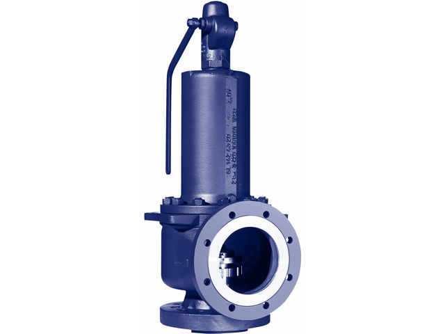
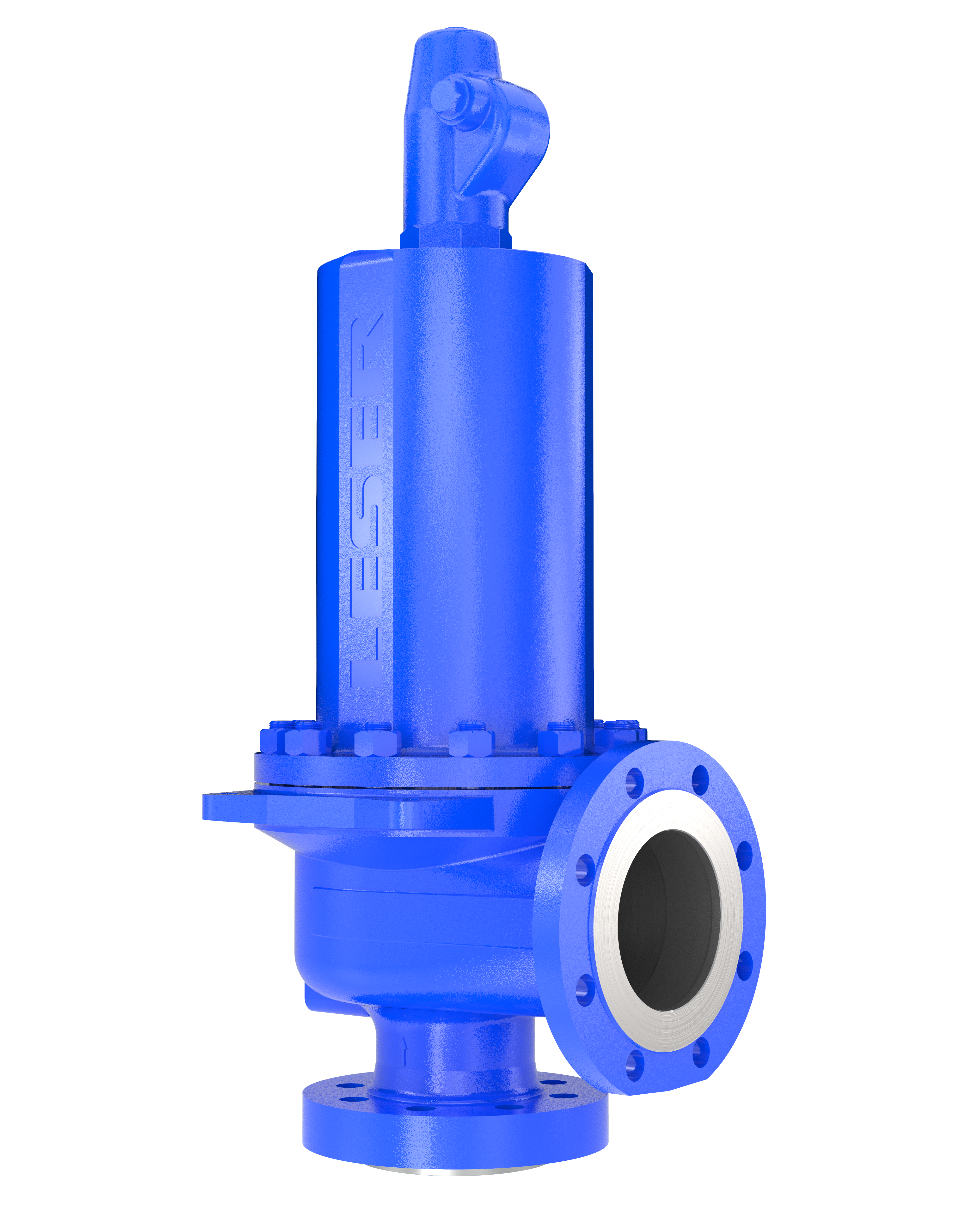
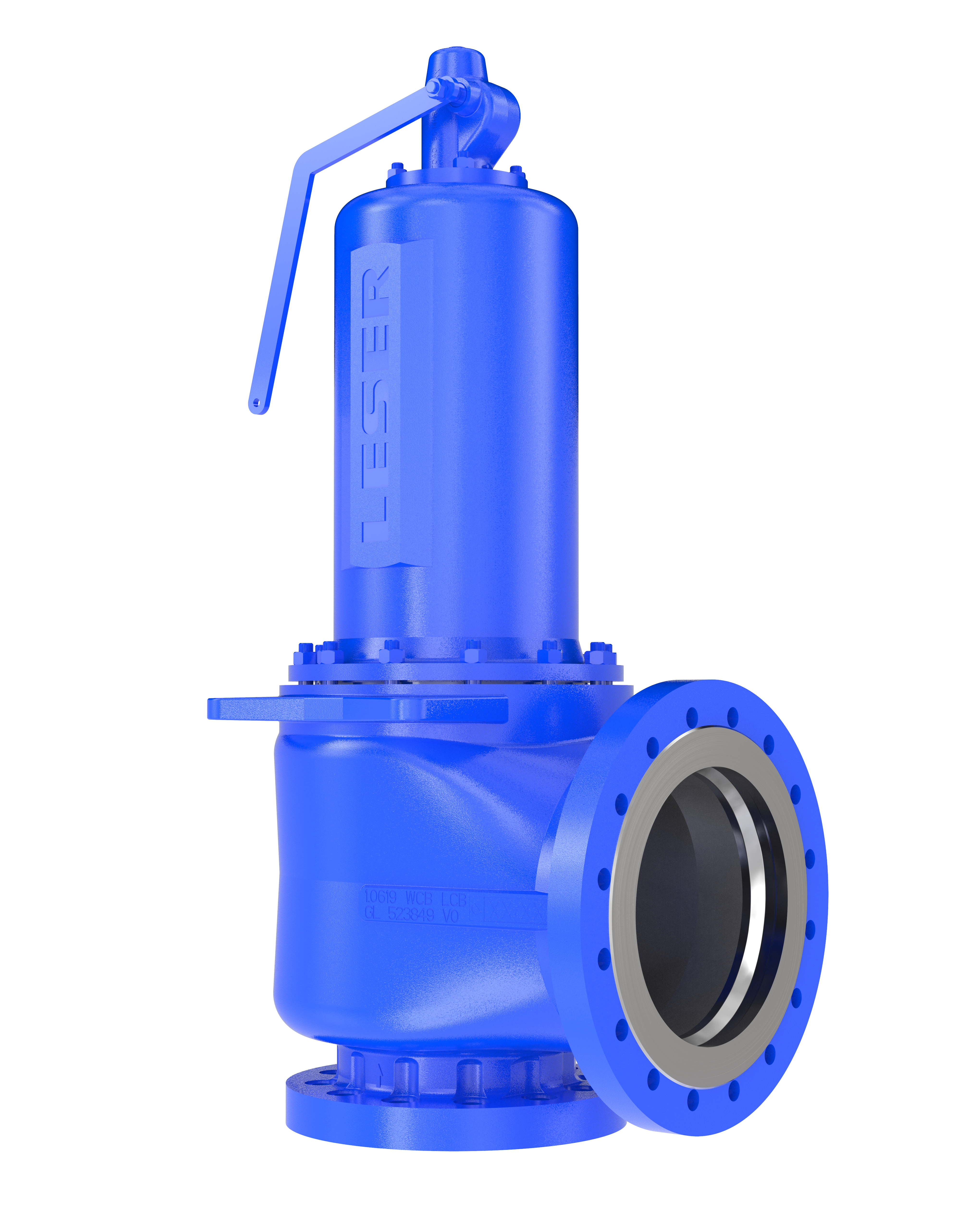
Type FL 441 Standard Pressure Series for Steam, Gas or Liquid Service l Full Nozzle, Full Lift Safety Valve l Flanged connections meeting API l l l lrequirements. Size: 25mm (Inlet) to 200mm (Inlet) Pressure Range: 0.15 bar g to 40.0 bar g (max.) (32.0 bar g max. for steam service) IBR approved (C=38) CCoE approved
Type FL 441 High Pressure Series for Steam, Gas or Liquid Service l Full Nozzle, Full Lift Safety Valve l Flanged connections l Size: 25mm (Inlet) to 100mm(Inlet)
Type FL 539 Series for Gas or Liquid Service l l l l lModified Nozzle Safety Relief Valve Screwed connections Compact design with light weight construction Size: 15mm (Inlet) Pressure Range: 0.5 bar g to 150 bar g
Type FL 549 Series Safety Relief Valve for Gas, Liquid or Jacket Heating Steam Service. Also for Thermal Relief Application l l l l l lModified Nozzle Safety Relief Valve Screwed as well as flanged connections Size: 15mm (Inlet) to 40mm (Inlet) Pressure Range: 0.5 bar g to 250 bar g Special construction possible for further higher Pressure CCoE approved
Method of Model NumberingFor Valve Type FL 441 SP SeriesAPI TUV H 74 ORIFICE LETTER ACC. TO API 526 D, E F G H J K, L M, N, P Q R T FLOW DIA "do" ACC. TO TUV 18 23 29 37 46 60 74 92 98 125 165 C C C6 S6 MATERIAL TYPE C6 - CS, ASTM A 216 WCB (SS 316 TRIM) SL - SS, ASTM A 351 CF 3 (SS 316 L TRIM) S5 - SS, ASTM A 351 CF 8 (SS 316 TRIM) S6 - SS, ASTM A 351 CF 8M (SS 316 TRIM) CH - CS, ASTM A 216 WCB (HASTELLOY C TRIM) SH - SS, ASTM A 351 CF 8M (HASTELLOY C TRIM) 6L - SS, ASTM A 351 CF 3M (SS 316 L TRIM) HS - ASTM A 217 GR. WC6 (SS 316 TRIM) LS - ASTM A 352 GR. LCB (SS 316 TRIM) AY - ALLOY - 20 (ALLOY - 20 TRIM) HY - HASTELLOY - "C" (HASTELLOY - "C" TRIM) SP - SPECIAL C8 - CS, ASTM A 216 WCB (SS 316 L TRIM) 00 - 1 4 22 AA CONNECTION RATING FOR INLET & OUTLET ABC012345ANSI 150 # ANSI 300 # ANSI 600 # OTHER, TO SPECIFY PN 10 PN 16 PN 25 PN 40 PN 64 4 2 X3
NOTEPrefix B is used in the 1st block along with orifice letter/flow dia for IBR (Indian Boiler Regulations) approved valves. Other special material also available. Please check specific quotation for model number
PROCEDURE FOR VALVE SIZING & SELECTIONFirst refer to Type FL 441, Standard Pressure Series. If the range is insufficient, refer to Type FL 441, High Presure Series. .. Valves manufactured by FAINGER LESER based on DIN design are type tested & approved by the International Agency, TUV (the German Type Test approving Authority) and the local statutory bodies like the CCoE (Chief Controller of Explosives), the IBR (Indian Boiler Regulations Act, 1950) etc. Sizing calculations are according to ASME Sec. VIII Div. 1 / API RP 520 or DIN 3320 / TRD 421, AD-Merkblatt 2000 - A2, ISO 4126, IBR 1950, where applicable. For IBR Valves of FAINGER LESER, the assigned value of constant is: C=38. Relieving capacity of the selected Valve would meet the customer required capacity. Flange rating and center to face dimensions are according to API 526 / DIN 3320. Valves with special connections and different center to face dimensions can also be provided on request. FAINGER LESER Valves are tested for seat leakage according to API 527.
Standard Materials for Valve Type FL 441 Standard Materials (Standard Pressure Series)STANDARD MATERIAL (Also Refer to Method of Model Numbering for Details) C61 A 216 Gr. WCB AISI 316 AISI 316 A 216 Gr. WCB AISI 316 A 216 Gr. WCB AISI 316 AISI 316 CS CD. PLATED AISI 316 AISI 316 A 216 Gr. WCB CS CD. PLATED/ ALLOY STEEL A 193 Gr. B7 A 194 Gr. 2H SS SS C.A.F./Non Asb. SS C.A.F./Non Asb. LEAD MS CS SS AISI 316 AISI 316 SS CS CS S54/S64 A 351 CF 8/8M AISI 316 AISI 316 A 351 CF 8/8M AISI 316 A 351 CF 8/8M AISI 316 AISI 316 AISI 316 AISI 316 AISI 316 A 351 CF 8/8M SS/ ALLOY STEEL A 193 B8/B8M A 194 Gr. 8/8M SS SS C.A.F ./Non Asb. SS C.A.F ./Non Asb. LEAD MS CS SS AISI 316 AISI 316 SS AISI 316 SS SPECIAL-1 A 217 Gr. WC6 AISI 316 AISI 316 A 216 Gr. WCB AISI 316 A 217 Gr. WC6 AISI 316 AISI 316 CS CD. PLATED AISI 316 AISI 316 A 216 Gr. WCB ALLOY STEEL A 193 Gr. B7 A 194 Gr. 2H SS SS C.A.F./Non Asb. SS C.A.F./Non Asb. LEAD MS CS SS AISI 316 AISI 316 SS C.S. C.S. SPECIAL-2 A 352 Gr. AISI 316 AISI 316 A 351 Gr. AISI 316 A 352 Gr. AISI 316 AISI 316 AISI 316 AISI 316 AISI 316 A 351 Gr. SS LCB SPECIAL-3 A 351 Gr. CF Hastelloy-C Hastelloy-C A 351 Gr. CF AISI 316 A 351 Gr. CF AISI 316 AISI 316 AISI 316 AISI 316 AISI 316 A 351 Gr. CF SS 8/8M
1. Flange ratings and center to face dimensions are according to API RP 526 as applicable for Full Nozzle Safety Valves of inlet size 1" (25mm) and above. 2. For revised sizes due to higher pressure & Temp., refer to page # 7/06. 3. For smaller sizes, refer to FL 539 & FL 549 series.
A BSP/NPT control thread is fitted into the bonnet to monitor the efficiency of the bellows. A discharge pipe can be attached to the threaded drain, in the event that provisions have to be made for a safe discharge of fluids in special cases e.g. aggressive or toxic fluids. The design height of the safety valve is altered if the stainless steel bellows are installed. NOTE
2. Safety Valves with Heating JacketSafety Valve can be fitted with a heating jacket for special applications. Areas of application are systems to be protected from media, which are viscous, sticky or have tendency to crystallize out of solution. In case of flanged Safety Valves without stainless steel bellows, only the bodies are fitted with a heating jacket. The heating connections for these Safety Valves shall be NPT female or ANSI 150 # RF.
Safety Valves with stainless steel bellows For Safety Valves with stainless steel bellows, the bonnet spacer required to house the bellows is fitted with an additional heating jacket. Both heating jackets are joined by a threaded pipe bend.
3. Safety Valves with Cooling Spacer for higher temperature (above 400 oC)To protect the sliding parts and the spring against inadmissible influence of temperature an additional equipment will be necessary for all flanged spring loaded valves if the fluid temperature is 400 oC (752 oF) and higher. If the temperature is higher than 450 oC (842 oF) stainless steel bellows should be provided as far as they are not fitted already by reason of the back pressure ratio.
In order to allow the adjustment of each Safety Valve in a plant provided with several Safety Valves or to carry out a pressure test above the allowable operating pressure a test gag is required. The test gag is fitted in the lever cover and exerts force on top of the spindle. After testing the test gag shall be removed.
5. Safety Valves with Lift StopperThat Safety Valves are only available in standardized nominal diameters, the valve could in a given application be oversized. It is therefore recommended to reduce the lift by means of a lift stopper, thus reducing the coefficient of discharge in addition. Lift stoppers must allow a lift of at least 1 mm.
Instructions for the Treatment and Installation of Pressure Relief Valves.1. General NotesPressure Relief Valves are highly quality instruments which should be handled with great care. To ensure the correct performance of a pressure relief valve all parts are made with exact precision. Only this precision ensures the correct functioning of the pressure relief valves. Careless handling of the finished valve in workshops, stores, during transportation or installation could cause leakage or possibly permanent damage (also refer to API Report Guide for inspection of refinery equipment, Chapt. XVI Pressure Relieving Devices" Para 1603082 and 1603083). The sealing surfaces have been ground and lapped with high precision to ensure the required tightness. Even though the surfaces are extremely hard, the seal can still be damaged. By all means, one must take care to prevent impurities from entering the valve during transportation, installation and operation. When installing pressure relief valves with threaded connections, use only metal seal washers. Seal materials such as hemp or PTFE tape should not be used as this type of material can break off and enter the valve causing it to leak. If valves with open bonnets and/or levers are to be painted after despatch from the factory, care must be taken to protect the sliding parts. Otherwise the correct operation of the pressure relief valve may be affected.
According to rules a drain hole of sufficient size must be incorporated at the lowest point of pipe work. In all cases the discharge pipe must first slope in a downwards direction and fitted with a suitable size drain hole before any bends are connected (refer to sketch). Exception: In special cases, for instance on board of ships an optional drain hole may be recommended in the valve body as it may be that pipe work drainage cannot be guaranteed at a lower point than the valve. The standard drain hole which will then be supplied by the factory is 1/4" BSP . But, by all means, the discharge pipe must be drained too. In extreme cases this hole can be drilled outside of our factory provided that special care is taken to ensure that no damage is done to the sealing surfaces. All drainage pipes that have been connected must be free of restriction and the ends easily seen. Care must be taken when discharging any drainage to prevent injury to personnel. For example on steam connect a suitable steam trap. Note! When valves are supplied with a drain hole that is not going to be used the plastic plug fitted in the hole must be removed and replaced by a metal plug. 3.3 Mounting Brackets For pressure relief valves with mounting brackets a fastening possibility for the brackets should be provided to withstand the forces of reaction when valve blows off. The bracket holes can be drilled on request. 3.4 Insulation In case any insulation of the pressure relief valve is provided, the bonnet must be kept free to avoid unacceptable heating up of the spring. 3.5 Inlet Pipe The inlet pipe for pressure relief valves should be as short as possible and should be so arranged, that when the valve is in its fully open position the pressure drop must not exceed 3% of set pressure, the edging at the inlet pipe should be rounded off or at least be chamfered. If the calculation results in a higher than 3% pressure drop of set pressure then the inlet pipe size must be enlarged. 3.6 Discharge Pipes/Back Pressure The discharge piping on vapours and gases should be installed in an ascending direction, on liquids in an inclined direction.
2. Transport ProtectionThe inlet and outlet of the pressure relief safety valves are protected during transportation with plastic caps. These caps should only be removed just before installing the valve. The lifting lever of spring loaded pressure relief valves is secured with a wire to the bonnet. This wire should be removed only after installation. For testing the set pressure or tightness of the pressure relief valve remove also this wire and take care that the lever is not engaged with the spindle cap.
3. Installation/Assembly3.1 General Notes Spring loaded pressure relief valves should be installed with the bonnet VERTICALLY UPWARDS. Furthermore, pressure relief valves should be mounted in such a way that no inadmissible static, dynamic or thermal loads can be transmitted to the valve due to up and downstream pipe work. If necessary, expansion possibilities should be provided. Stresses by incorrect mounting should be avoided. 3.2 Draining of Condensate To prevent dirt and all kinds of impurities from the pressure relief valve the drainage of discharge pipe and pressure relief valve must be done via discharge pipe. Therefore, FAINGER LESER pressure relief valves are not normally provided with drain holes.
Instructions for the Treatment and Installation of Pressure Relief Valves.It is recommended and in Germany required by Rules to lift manually the valve lifting lever from time to time in order to prevent accumulation of deposits that will affect valve operation. For steam generators, the following requirements are established in the German Technical Rules for Steam Boilers TRD 601, edition 6.83, Section 6. "Testing of pressure relief valves is required for plants operating with demineralized water and for hot water generators at intervals of at least 6 months, with the exception of power plants. For other steam generators, the test interval should not exceed 4 weeks". It is important to ensure that the lifting lever does not engage the spindle cap after the lift operation. The lever must be deflected towards the center line of the bonnet until the lifting fork is disengaged. For pressure relief valves with open bonnet, a drain groove is provided in the guide flange. Whilst blowing, condensate escaping through the clearance between guide disc and spindle is drained through this groove. According to DIN specification 4754, Oct. 74 Edition "Explanations", Para 4.4 pressure relief valves represent the last step in the line of protection for the vessel, and they should be able to prevent excess pressure when all other automatic or pilot operated checking instruments have failed. To guarantee this function pressure relief valves require, like all other technical equipment, regular service. How often a valve must be checked, depends on the actual operating conditions, so that no general indications can be given. Usually pressure relief valves operating in a corrosive atmosphere or on laden fluids require service more often than valves operating clean conditions. This also applies if the pressure relief valve operates frequently causing a higher wear out to the seat and disc. Special consideration is required if conditions such as vibration (to be avoided, if possible) pressure pulsation and/or a too small difference between working and set pressure cannot be avoided.
The discharge pipework of all pressure relief valves should be so arranged that the back pressure, which is built up during blow off, does not exceed a max. 15% of set pressure. In case of higher back pressure, pressure relief valves with pressure compensating metal bellows (balanced type) shall be used. In case the back pressure is >0.15 times set pressure the capacity of the pressure relief valves must be recalculated. 3.7 Pressure Relief Valves with bellows Pressure relief valves with elastomer bellows (TRD 721) as well as metal bellows have a vent hole in the bonnet. When fitting pressure relief valve with a vent hole care must be taken to prevent moisture from entering the bonnet. However, fluid escaping from the vent hole indicates that the bellows have failed. Repair is required. When pressure relief valves with bellows are used with toxic or inflammable fluids, care must be taken to fit a suitable vent pipe to provide safe venting. For this purpose, the vent can be threaded 1/4" BSP female on request.
4. Mode of Operation/MaintenanceThe working pressure of the plant should be at least 5% below the blow down pressure of the valve to enable a correct reseat. When a slight leakage occurs, due to deposits between the sealing surfaces, surfaces can be cleaned by operating the lifting lever causing the valve to blow off. The valve should be closed by sudden release of the lever. If this procedure does not stop the leakage, the valve seals are probably damaged. Repairs should be carried out at our workshop or by a qualified person.
Dismantling and Assembly InstructionsFor Valve Type FL 441, FL 459 & FL 549 Series1. Loosen the existing lead seal. 2. Press the lever (43) towards the middle until it reaches the stop so that the lifting fork(44) no longer holds the spindle cap (46). 3. Loosen and remove the lever cover (41). 4. Loosen the spindle cap (46) from the spindle (12), remove the securing ring (91) and the pin (74). 5. Loosen the lock nut (19) of the adjusting screw (18). 6. Turn the adjusting screw (18) anticlockwise to remove the all spring tension. 7. Remove the hex. nuts (56) from the flange of the bonnet (9). 8. Lift off the bonnet (9). 9. Remove the upper spring plate (16). 10. Lift of the spring (54) and remove lower spring plate (16) and split rings (14). 11. Remove spindle (12) with guide (8) and disc (7). 12. Carefully clean seat (5) and disc (7), and if required body internals. 13. Refit spindle (12) with guide (8) and disc (7). 14. Fit the split rings (14) into spindle groove and retain with the securing ring (59); slip on lower spring plate (16) to locate on split rings (14). 15. Replace spring (54).
16. Slip on the upper spring plate (16) onto the spindle (12). 17. Align adjusting screw (18), and bonnet (9), over the spindle (12) and refit. 18. Fit and tighten the hex. nuts (56). 19. Load the spring (54) to obtain the required set pressure. Clockwise rotation of adjusting screw (18) increases pressure. Anticlockwise rotation of adjusting screw (18) reduces pressure. 20. Tighten the lock nut (19) onto the adjusting screw (18). 21. Refit and secure spindle cap (46) by pin (74) and securing (91). 22. Screw-on the lever cover (41). 23. Pull the lever (43) towards the middle so that the lifting fork (44) is pushed under the spindle cap (46). 24. Test spindle will lift correctly by pulling lever. These instructions are applicable for Relief Valves, Safety Valves and Safety Relief Valves.
Spring Replacement1. Remove lead seal. 2. Remove pin (74). 3. Pull lever (43) from lever cover (41). 4. Unscrew and remove lever cover (41). 5. Remove Pin (74). 6. Remove spindle cap (46) from spindle (12). 7. Slacken lock nut (19) of adjusting screw (18). 8. Turn adjusting screw (18) anticlockwise to remove all spring tension. 9. Unscrew bonnet (9), but first loosen discharge pipe. 10. Remove upper spring plate (17). 11. Lift off the spring (54). 12. Withdraw assembly of spindle (12), lower spring plate (16) and disc (7). 13. Carefully clean seat (1) and disc (7), and if required body internals. 14. Refit spindle (12) with lower spring plate (16) and disc (7). 15. Replace spring (54). 16. Slip on upper spring plate (17) to the spindle (12). 17. Align adjusting screw (18) and bonnet (9) over spindle (12) and refit. 18. Load the spring (54) to obtain the required set pressure. Draw attention to the admissible pressure range of the spring ! Clockwise rotation of adjusting screw (18) increases pressure. Anticlockwise rotation of adjusting screw (18) reduces pressure. 19. Tighten locknut (19). 20. Refit spindle cap (46) on the spindle (12). 21. Drive in pin (74). 22. Screw on lever cover (41). 23. Refit lever (43). 24. Drive in pin (74). 25. Seal the valve.
Method of Model NumberingFor Valve Type FL 441 HP SeriesAPI TUV *H *74 ORIFICE LETTER ACC. TO API 526 D, E F G H J K, L M, N, P C C C6 S6 MATERIAL TYPE C6 - CS, ASTM A 216 WCB (SS 316 TRIM) S5 - SS, ASTM A 351 CF 8 (SS 316 TRIM) S6 - SS, ASTM A 351 CF 8M (SS 316 TRIM) 4L - SS, ASTM A 351 CF 3 (SS 316 L TRIM) 6L - SS, ASTM A 351 CF 3M (SS 316 L TRIM) HS - ASTM A 217 GR. WC6 (SS 316 TRIM) 00 - OTHER, TO SPECIFY 1 4 52 CA 4 2 X3
NOTE1) Prefix B is used in the 1st block along with orifice letter/flow dia for IBR (Indian Boiler Regulations) approved valves. 2) For Valve Type FL 441, High Pressure Series, Prefix " * " is added in the 1st block.
PROCEDURE FOR VALVE SIZING & SELECTIONValves manufactured by FAINGER LESER based on DIN design are type tested & approved by the International Agency, TUV (the German Type Test approving Authority) and the local statutory bodies like the CCoE (Chief Controller of Explosives), the IBR (Indian Boiler Regulations Act, 1950) etc. Sizing calculations are according to ASME Sec. VIII Div. 1 / API RP 520 or DIN 3320 / TRD 421, AD-Merkblatt 2000 - A2, ISO 4126, IBR 1950, where applicable. For IBR Valves of FAINGER LESER, the assigned value of constant is: C=38. Relieving capacity of the selected Valve would meet the customer required capacity. Flange rating and center to face dimensions are according to API 526 / DIN 3320. Valves with special connections and different center to face dimensions can also be provided on request. FAINGER LESER Valves are tested for seat leakage according to API 527.
Method of Model NumberingFor Valve Type FL 459 Series09 FLOW DIA 09 / C S6 4 S S CONNECTION RATING FOR INLET & OUTLET S - SCREWED 0 - OTHER, TO SPECIFY 4
PROCEDURE FOR VALVE SIZING & SELECTIONValves manufactured by FAINGER LESER are based on DIN design. Relieving capacity of the selected valve would meet the customer required capacity. Sizing calculations are according to DIN 3320 / TRD 421, AD-Merkblatt 2000-A, ISO 4126 or ASME Sec. VIII Div. 1/ API RP 520, where applicable. These Valves are approved by IBR. FAINGER LESER Valves are tested for seat leakage according to API 527.
Method of Model NumberingFor Valve Type FL 539 Series10 FLOW DIA 10 12.5 / C S6 4 S S CONNECTION RATING FOR INLET & OUTLET S - SCREWED 0 - OTHER, TO SPECIFY 4
PROCEDURE FOR VALVE SIZING & SELECTIONValves manufactured by FAINGER LESER are based on DIN design. Relieving capacity of the selected valve would meet the customer required capacity. Sizing calculations are according to DIN 3320 / TRD 421, AD-Merkblatt 2000-A2, ISO 4126 or ASME Sec. VIII Div. 1/ API RP 520, where applicable. FAINGER LESER Valves are tested for seat leakage according to API 527.
51*= Basic valve assembly fitted with 2* and 4*Item 1 7 9 12 16 17 18 19 27 50 54 57 59 60 61 Part Name Inlet Body Disc Compl. Bonnet Spindle Lower Spring Plate Upper Spring Plate Adjusting Screw Lock Nut Guide Name Plate Spring Pin Securing Ring Gasket Ball
Method of Model NumberingFor Valve Type FL 549 Series19 / C S6 MATERIAL TYPE C6 - CS, ASTM A 216 WCB (SS 316 TRIM) S5 - SS, ASTM A 351 CF 8 (SS 316 TRIM) S6 - SS, ASTM A 351 CF 8M (SS 316 TRIM) 5L - SS, ASTM A 351 CF 3 (SS 316 L TRIM) 6L - SS, ASTM A 351CF 3M (SS 316 L TRIM) CH - CS, ASTM A 216 WCB (HASTELLOY C TRIM) SM - SS, ASTM A 351 CF 8M (MONEL TRIM) HS - ASTM A 217 GR. WC6 (SS 316 TRIM) LS - ASTM A 352 GR. LCB (SS 316 TRIM) AY - ALLOY - 20 (ALLOY - 20 TRIM) HY - HASTELLOY - "C" (HASTELLOY- "C" TRIM) SP - SPECIAL 00 - 4 22 CONNECTION RATING FOR INLET & OUTLET ABCDE F 0S 1234567ANSI 150 # ANSI 300 # ANSI 600 # ANSI 900 # ANSI 1500 # ANSI 2500 # OTHER, TO SPECIFY SCREWED PN 10 PN 16 PN 25 PN 40 PN 64 PN 100 PN 160 4 X3
PROCEDURE FOR VALVE SIZING & SELECTIONValves manufactured by FAINGER LESER are based on DIN design. Relieving capacity of the selected valve would meet the customer required capacity. Sizing calculations are according to DIN 3320 / TRD 421, AD-Merkblatt 2000 - A2, ISO 4126 or ASME Sec. VIII Div. 1 / API RP 520, where applicable. These valves are approved by the CCoE (Chief Controller of Explosives), Nagpur. FAINGER LESER Valves are tested for seat leakage according to API 527.
Assembly of a Spring Loaded Safety Valve1*= Basic valve assembly fitted with 2*and 4*Item 75 Part Name Inlet Body Outlet Chamber Disc Compl. Spindle Guide Bonnet Spindle Split Ring Spring Plate Adjusting Screw Lock Nut Name Plate Spring Pin Securing Ring Gasket Ball
Safety Valve can be fitted with a heating jacket for special applications. Areas of application are systems to be protected from media, which are viscous, sticky or have tendency to crystallize out of solution. Outlet Chamber, item 2, is fitted with heating jacket. The heating connections of these Safety Valves shall be 3/8 NPT female
2. Safety Valves with Test GagIn order to allow the adjustment of each Safety Valve in a plant provided with several Safety Valves or to carry out a pressure test above the allowable operating pressure a test gag is required. The test gag is fitted in the lever cover and exerts force on top of the spindle. After testing the test gag shall be removed.
3. Safety Valves with Lift StopperThat Safety Valves are only available in standardized nominal diameters, the valve could in a given application be oversized. It is therefore recommended to reduce the lift by means of a lift stopper, thus reducing the coefficient of discharge in addition.
Symbols and Units Symbol A C Kb Kd Kdr Kv k M n Po Pb Pc Qm qm q"m R To Tc m n x Z Description Flow area of a safety valve (not curtain area) Function of the isentropic exponent Theoretical capacity correction factor for subcritical flow Coefficient of discharge* Certified derated coefficient of discharge (Kd x 0.9)* Viscosity correction factor Isentropic exponent Molar Mass Number of tests Relieving pressure Back pressure Critical pressure Mass flow rate Theoretical specific discharge capacity Specific discharge capacity determined by tests Universal gas constant Relieving temperature Critical temperature Dynamic viscosity Specific volume at actual relieving pressure and temperature Dryness fraction of wet steam at the valve inlet at actual relieving pressure and temperature** Compressibility factor at actual relieving pressure and temperature. * Kd and Kdr are expressed as 0.xxx. ** x is expressed as 0.xx. C = 3.948 k 2 (k + 1) / (k 1) k+1 Unit mm kg/kmol bar (abs.) bar (abs.) bar (abs.) kg/h kg/(h.mm) kg/(h.mm) K K Pa.s m/kg
The equations are used to calculate the required discharge area for a Safety Valve. The selected Safety Valve shall have an effective (flow) area, in accordance with the corresponding orifice letter, equal to or larger than that of the required area. Orifice Letter D E F G H J K L M N P Q R T NOTE * Please refer to page 7/06 also for any revision in size due to different pressure & temperature. Effective area in mm 0.110 71.0 0.196 126.5 0.307 198.1 0.503 324.5 0.785 506.5 1.287 830.3 1.838 1185.8 2.853 1840.6 3.600 2322.6 4.340 2800.0 6.380 4116.1 11.050 7129.0 16.000 10322.6 26.000 16774.2 Standard size * (inlet & outlet) inches 1x2 1x2 1 x 2 1 x 3 1 x 3 2x3 3x4 3x4 4x6 4x6 4x6 6x8 6 x 10 8 x 10
Sizing of Safety ValvesAcc. to ASME Sec. VIII, Div. 1/ API RP-520Value of Constant C based on cp/cv (k) Constant C 316 318 320 322 324 327 329 331 333 335 337 339 341 Constant C 343 345 347 349 351 352 354 356 358 359 361 363 364 Constant C 366 368 369 371 372 374 376 377 379 380 387 400 412
Back Pressure correction factor, Kb The back pressure correction factor Kb is used in the equations for calculating the effective discharge area for gases and vapours. The correction factor Kb is not required for Safety Valves with balanced bellows so far as the coefficient of discharge is not reduced for reason of the pressure ratio Pao/Po. Kb is determined as follows: Kb=1.0 for Pao 2 ------- --------Po k+1
D. Sizing Calculations as per Fire ExposureThere are various ways in which a pressure vessel can be subjected to heat in such a manner as to result in an unacceptably high pressure increase. One cause of such subjection to heat is an external fire. As the course of development of heat caused by external fire may vary considerably, depending on the cause of the fire, it is necessary to standardise these causes under the term standard fire. The amount of heat resulting from such a standard fire can be calculated using the formula specified in API RP-520 & 521. First of all, the wetted surface of the vessel is required to be determined. On the basis of this value, the total heat absorption, Q, can then be calculated using the formula from the above stated API standard. The mass flow W, which is to be discharged by the Safety Valve is then calculated from the total heat absorption, Q, and the heat of evaporation, L. On the basis of the determined mass flow, W, sizing of Safety Valve can then be established using standard formula as per ASME Sec.VIII, Div. 1/API RP-520.
In the formula for determining the total heat absorption, the thickness of the refractory insulation is represented by the environment factor, F. where: Formula Used, Q = Total heat absorption, Btu/h Q = 21000 x F x A 3 0.82 Q W = -------L = Environment factor for the insulation thickness = 1.0 for Bare Vessel = 0.3 for vessel with 25mm insulating thickness = 0.15 for vessel with 50mm insulating thickness = 0.075 for vessel with 100 mm insulating thickness = 0.03 for Earth covered vessel above ground = 0.0 for underground storage vessel A3 = Total wetted surface of vessel, ft W = Mass flow to be discharged by Safety Valve, lb/h L = Heat of evaporation, Btu/lb F
Valve Sizes / Flange Rating w.r.t. Set Pressure & Temperature (acc. to API 526)Set Pressure & Flange Rating for Temp. up to Standard Size inches 100 F (37.8 C) Set press. kg/cm2(g)1 D, E 1X2 1X2 1X2 1.5 X 2 1.5 X 2 1.5 X 2 1.5 X 3 1.5 X 3 1.5 X 3 1.5 X 3 1.5 X 3 1.5 X 3 AXA BXA CXA AXA BXA CXA AXA BXA CXA DXB AXA BXA 20.04 52.04 104.07 20.04 52.04 104.07 20.04 52.04 104.07 156.02 20.04 20.04
7where, A = Calculated throat/flow area, mm = p d /4; d = Calculated throat/flow dia, mm E = Required Relieving Capacity, kg/h C = IBR constant = 38 for FAINGER LESER make Safety Valves P = Set Pressure, bar abs. F = Superheat correction factor (F=1 for saturated steam)
For all steam service Safety Valves covered under IBR, the sizing calculations are based on IBR formula (IBR-1950, Regulation No. 293) as under. E x 100 A = --------------- x F CxP
Ts is degree of superheat, C NOTE Using the above formula, the smallest flow Area A shall be calculated to discharge the required mass flow. The flow area/dia selected shall be equal to or larger than the required one. Based on the selected flow area/dia, the inlet & outlet size of the Safety Valve shall be chosen to match with the size as indicated in API 526 or as per customer requirement.
Client : M/s.Sl.No./TAG No. Qty. (Nos.) Size, In X Out, mm Connections Conn. Std. & Rating M.O.C. Body Bonnet Trim Nozzle Disc Spring Bellow Material Cap (lever) Type Sizing Code Set Pressure kg/cm2 g Working Pressure Design Pressure Back Pr. Kg/cm2 g Overpressure % Fluid (Service) Fluid State Req. Rel Capacity Discharge Temp.oC Mol. Wt. / Sp.gr. Viscosity at flow temp. Cp/CV, if Gas/Vap Comp. Factor (Vap) Cal. Orifice Area, in2 Sel. Orifice Area, in2 Orifice Letter Act. Rel. Capacity Model No. Valve Type Inspection by
Fainger Leser Valves (P .) Ltd.136/137, Sanjay Bldg. No. 3, Mittal Estate, Marol, Andheri (E), Mumbai - 400 059 India. Tel : 91-22-2850 1692, 4277, 3617, 9747, 9751 l Fax : 91-22-2850 4470, 2851 0918 E-mail: info@faingerleser.com l Website: www.faingerleser.com7/08 FAINGER LESER 2011
FAINGER LESER Valves have the APPROVAL by most of the Consulting Engineering companies and Third Party Inspection agencies viz. Engineering Consultants l Aker Solutions l l l l l l l l l l l l l l l l l l l l l B. Mehtalia Consultants Pvt. Ltd. Chemtex Engineering of India Ltd. Dalal Mott MacDonald Pvt. Ltd. Development Consultants Ltd. DMCC-Monsanto Fichtner Consultants Hindustan Dorr-Oliver Ltd. Jacobs Engg. (I) Private Ltd. Knexir Consultants Pvt. Ltd. Linde Process Technologies Lurgi India Ltd. MECON Ltd. M.N. Dastur & Co. Ltd. Project & Development India Ltd. SNC Lavalin Engg. India Pvt. Ltd. Shroff & Associates TCE Consulting Engineers Ltd. Technip India Ltd. Tecnimont ICB Ltd. Toyo Engineering India Ltd. UHDE India Pvt. Ltd.
FAINGER LESER"s state-of-the-art, micro processor based in-house flow performance test facility disposes off air as the test medium which is used to test Valves for critical application and on customer"s specific request. The test facility comprises of two large air compressors for generating air pressure up to 100 bar. The high pressure air up to 100 bar is stored in the series of high pressure bullets outside the building in order to provide a continuous supply of air for the flow performance test of Safety Valves. Inside the test building, there are 10 more bullets to store the pressure up to 50 bar. The pressure is controlled between the outside and inside bullets through high precision Controllers and Control Valves. The pressure transmitters, flow transmitters etc. are mounted on the test bullets and the signal from the tapping across the orifice plate is used to measure the differential pressure. The electronic lift indicator records the actual Valve lift. DAS (Data Acquisition System) software provides graphic printout of the observed readings/result. Flow performance test is carried out for a period of 30 seconds depending on the limitation of the test facility, (by creating the simulated site conditions) and following parameters are measured: Popping Pressure Reseating Pressure Flow Lift The behavioral pattern can be further analyzed/viewed by zooming the graph at various points. The measured flow can be compared with the theoretical flow to ascertain the coefficient of discharge used in the sizing of Safety Valves. For all special cases where the flow is to be restricted to certain quantity, a lift stopper can be used and the performance test can be conducted to ensure the customer"s required flow through the Valve. The Flow Performance tests can be offered at a very reasonable extra cost.Date : 10/11/2002 Time : 16:37:06
The microprocessor operated flow characteristic testing facility is used where required to ensure valve operating performance & relieving capacity with air as the test medium.
DATE OF TEST TIME OF TEST TEST No. CLIENT P . O. No. VALVE SERIAL No. VALVE TAG No. VALVE TYPE VALVE SIZE ORIFICE LETTER ORIFICE AREA OF VALVE FLOW/THROAT DIA. INTENDED SERVICE OPERATING TEMP OPERATING PRESSURE SET PRESSURE ACCUMULATION TEST LINE SIZE TEST MEDIUM ORIFICE BORE BAROMETRIC PRESSURE BAROMETRIC PRESSURE
POPPING PRESSURE RESEATING PRESSURE BLOWDOWN VALVE LIFT FOR GIVEN ACCUMULATION P1, STATIC PRESSURE AT METER P1A, STATIC PRESSURE AT METER T1, UPSTREAM TEMP . T1A,UPSTREAM TEMP . T2, RELIEVING TEMP . T2A, RELIEVING TEMP . COMPRESSIBILITY FACTOR Z= 0.997 FLOW MEASURING PRESSURE MEASURED FLOW, V a d h 0.798* t = = =
THEORETICAL FLOW, Vt C * Aa * P * M Where, T * Z1 C = COEFF. BASED ON cp/cv Aa = VALVE DISCHARGE AREA, (ORIFICE AREA OF VALVE) P = FLOW MEASURING PRESSURE =SET PR. * (1 + ACCUM / 100) T = T2A, RELIEVING (DRUM) TEMP . Z1 = COMPRESSIBILITY FACTOR M = MOLECULAR WEIGHT KD = COEFF. OF DISCHARGE, V/Vt
...a not so brief history of LESEREstablished in the year 1818, LESER is the number one supplier of Safety Valves in Europe and strengthens this position each year. Headquartered in Germany, with a stateof-the-art factory and more than 290 employees LESER is supplying high quality Safety Valves all over the world.
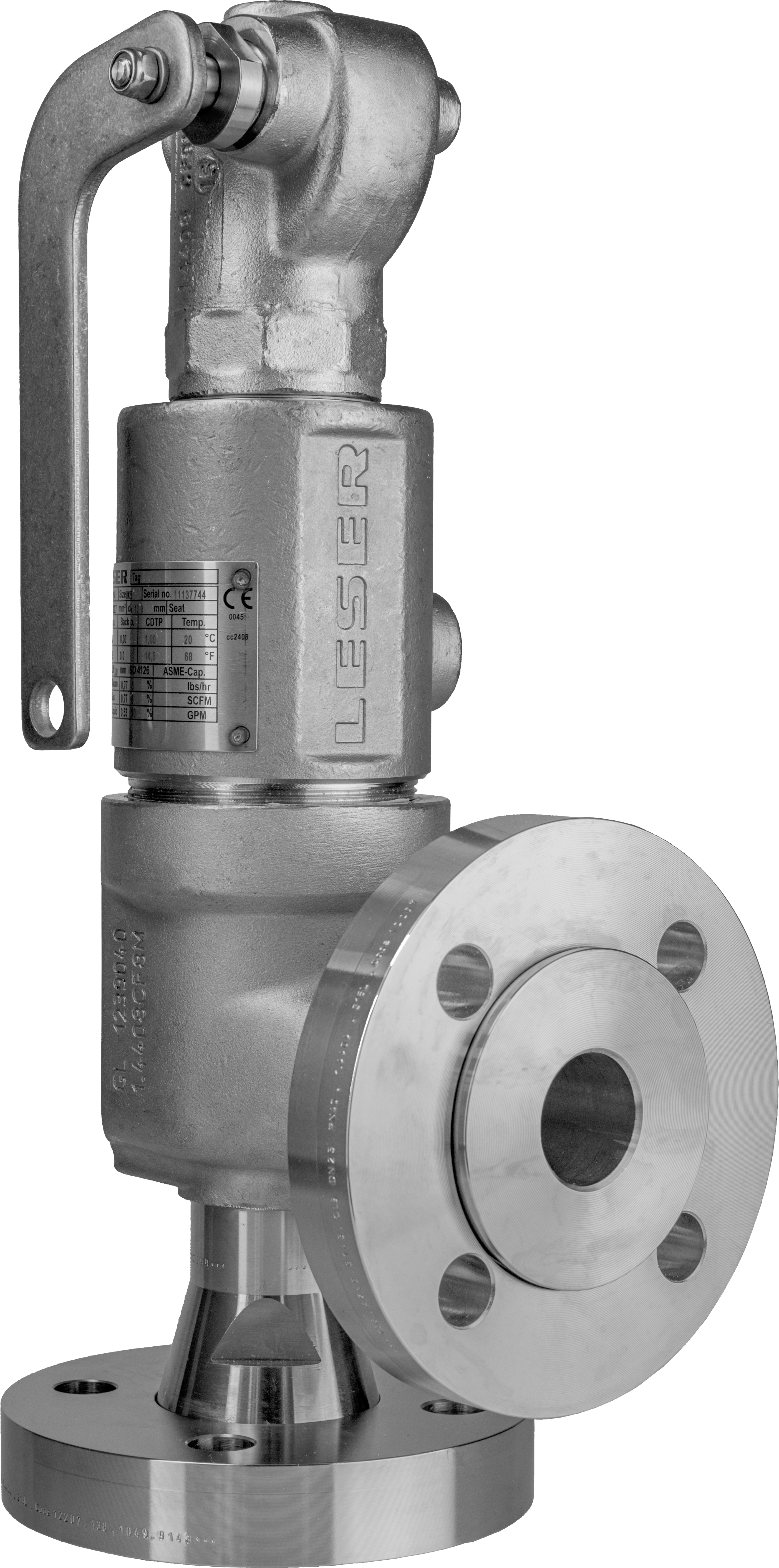
API SeriesSeries 526Applications Oil and gas Refineries Chemical Industry Petrochemical Industry Product Features Valve sizes 1" through 8", Orifice D through T Materials: WCB, CF8M, WC6, LCB, specials Design according to API 526 Standard metal sealing, stellited, or O-ring disc for superior tightness Optional stainless steel bellows Single trim for steam, gas and liquid
Compact performanceSeries 459 - Series 437Applications Thermal relief Air / Gas compressors and pumps Technical gases and CO2 plants LPG / LNG terminals, carriers etc. Chemical equipment and piping Cryogenic systems and oxygen applications Product Features Valve sizes from " through 1" Materials: carbon steel, stainless steel, specials Threaded or flanged connections Set pressure range up to 11600 psig Standard metal sealing, stellited, or O-ring disc for superior tightness Optional stainless steel bellows Single trim for steam, gas and liquid
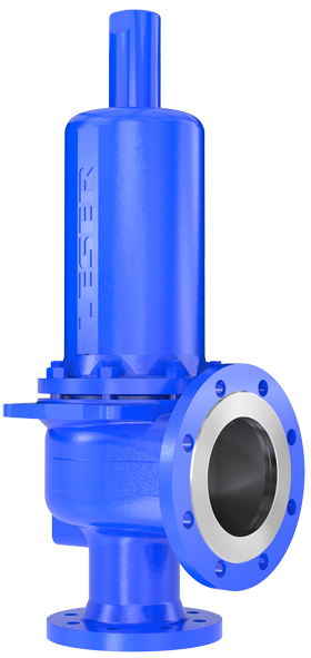
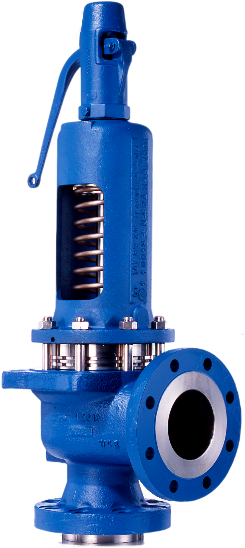
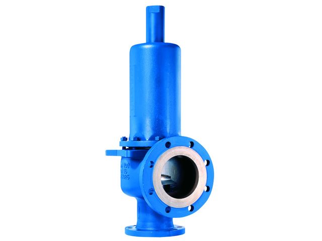
High performanceSeries 441Applications Heat exchanger Chemical equipment and piping General steam installations Pressure vessels and piping systems containing gas, air, liquid or steam Air / gas compressors & pumps Product Features Valve sizes from 1" through 16" Materials: WCB/carbon steel or CF8M/stainless steel Standard metal sealing, stellited, or O-ring disc for superior tightness Optional stainless steel bellows High capacity compared to the API requirements Single trim for steam, gas and liquid
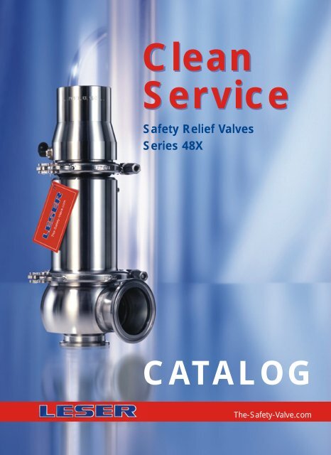
10Product Features Valve sizes 1" through 4" Materials: 316L stainless steel, specials No bacteria traps or contamination Minimum dead leg design and flushmounting capability Gap and crevice free design of internals Optional pneumatic lifting device and proximity switch for plant automation. Wetted-part surfaces acc. to ASME BPE 2002 Standard elastomer bellows for protection of the hard to clean parts. Single trim for steam, gas and liquid
Product Features Valve sizes 1" through 4" Body: WCB, PTFE-lined Isostatic lining in virgin PTFE Smooth PTFE surfaces, no adherence Nozzle: PTFE/glass sintered Single trim for gas and liquid
Best AvailabilitySeries 310 Series 311 Change over ValveApplications Continuously functioning plant Bitumen refineries Oilfields Ethylene plants Non-drainable systems Natural gas caverns Storage tanks Product Features Valve sizes 1" through 16" Body: WCB, CF8M Compact design Full flow area on change-over Standard stuffing box or optional stainless steel bellows Low pressure losses on discharge flow (3% criterion)


 8613371530291