
nozzle reaction safety valve supplier
As soon as mankind was able to boil water to create steam, the necessity of the safety device became evident. As long as 2000 years ago, the Chinese were using cauldrons with hinged lids to allow (relatively) safer production of steam. At the beginning of the 14th century, chemists used conical plugs and later, compressed springs to act as safety devices on pressurised vessels.
Early in the 19th century, boiler explosions on ships and locomotives frequently resulted from faulty safety devices, which led to the development of the first safety relief valves.
In 1848, Charles Retchie invented the accumulation chamber, which increases the compression surface within the safety valve allowing it to open rapidly within a narrow overpressure margin.
Today, most steam users are compelled by local health and safety regulations to ensure that their plant and processes incorporate safety devices and precautions, which ensure that dangerous conditions are prevented.
The principle type of device used to prevent overpressure in plant is the safety or safety relief valve. The safety valve operates by releasing a volume of fluid from within the plant when a predetermined maximum pressure is reached, thereby reducing the excess pressure in a safe manner. As the safety valve may be the only remaining device to prevent catastrophic failure under overpressure conditions, it is important that any such device is capable of operating at all times and under all possible conditions.
Safety valves should be installed wherever the maximum allowable working pressure (MAWP) of a system or pressure-containing vessel is likely to be exceeded. In steam systems, safety valves are typically used for boiler overpressure protection and other applications such as downstream of pressure reducing controls. Although their primary role is for safety, safety valves are also used in process operations to prevent product damage due to excess pressure. Pressure excess can be generated in a number of different situations, including:
The terms ‘safety valve’ and ‘safety relief valve’ are generic terms to describe many varieties of pressure relief devices that are designed to prevent excessive internal fluid pressure build-up. A wide range of different valves is available for many different applications and performance criteria.
In most national standards, specific definitions are given for the terms associated with safety and safety relief valves. There are several notable differences between the terminology used in the USA and Europe. One of the most important differences is that a valve referred to as a ‘safety valve’ in Europe is referred to as a ‘safety relief valve’ or ‘pressure relief valve’ in the USA. In addition, the term ‘safety valve’ in the USA generally refers specifically to the full-lift type of safety valve used in Europe.
Pressure relief valve- A spring-loaded pressure relief valve which is designed to open to relieve excess pressure and to reclose and prevent the further flow of fluid after normal conditions have been restored. It is characterised by a rapid-opening ‘pop’ action or by opening in a manner generally proportional to the increase in pressure over the opening pressure. It may be used for either compressible or incompressible fluids, depending on design, adjustment, or application.
Safety valves are primarily used with compressible gases and in particular for steam and air services. However, they can also be used for process type applications where they may be needed to protect the plant or to prevent spoilage of the product being processed.
Relief valve - A pressure relief device actuated by inlet static pressure having a gradual lift generally proportional to the increase in pressure over opening pressure.
Relief valves are commonly used in liquid systems, especially for lower capacities and thermal expansion duty. They can also be used on pumped systems as pressure overspill devices.
Safety relief valve - A pressure relief valve characterised by rapid opening or pop action, or by opening in proportion to the increase in pressure over the opening pressure, depending on the application, and which may be used either for liquid or compressible fluid.
In general, the safety relief valve will perform as a safety valve when used in a compressible gas system, but it will open in proportion to the overpressure when used in liquid systems, as would a relief valve.
Safety valve- A valve which automatically, without the assistance of any energy other than that of the fluid concerned, discharges a quantity of the fluid so as to prevent a predetermined safe pressure being exceeded, and which is designed to re-close and prevent further flow of fluid after normal pressure conditions of service have been restored.

In addition to the small installation space of the above-mentioned compressors, they should be completely covered by an acoustic enclosure to reduce noise emissions. In order to reduce the size of the very cost-intensive sound enclosure, AERZEN requires special valves that are adapted to the available small installation space. Compressors are discontinuous machines for pressure generation.
In order to ensure that occurring pulsations do not impair the function of the safety valve, the set pressure of the valve is adjusted accordingly and an appropriate distance to the pressure line is ensured by design.
The LESER solutionAs a renowned manufacturer of safety valves, it is advantageous to be able to react flexibly to the above-mentioned concerns, primarily to the small installation space, with its portfolio. Being able to change the installation position of safety valves is a clear advantage for the compressor designer. They are much more variable in their design and construction options and can also respond more flexibly to special customer specifications. If the progressive modularization of compressors requires more compact designs, safety valves in different mounting positions, for example, can be an answer to the problem, unlike the classic upright position. In addition, the spindle guide plays a special role here. The friction at the guiding points must be reduced as much as possible so that the spindle runs smoothly. Otherwise, a safety valve can only be installed vertically.
Why LESER safety valves?For a global acting OEM like AERZEN, a specialist like LESER, who has not only the knowledge but also the necessary approvals, is an important component for success. LESER offers a global approval concept that allows safety valves to be used regardless of location. When ordering safety valves, only the applicable regulations must be specified in order to ensure appropriate labeling and material selection. In addition, LESER has tested and approved further installation positions in addition to the conventional installation situation, standing on the inlet pipeline. For example, some types of valves may be installed with a horizontal stem or even upside down, e.g. Types 526 and 441. For horizontal installation, care must be taken to align the outlet. Liquids, e.g. in the form of condensate, should be able to drain off downwards to avoid back pressures and even corrosion. When installed upside down, the inverted weight forces are corrected by correction factors. LESER offers not only safety valves with basic documentation and accessories but also other special documentation and options. From the “Fugitive Emission Test” with helium up to 3.2 ship class castings and from back pressures up to more than 200 bar-g to high pressure heating jackets for up to 30 bar-g, LESER sales engineers develop solutions for customer specific applications as described above for AERZEN.

The new TFT Working Fire nozzle delivers revolutionary performance when you need maximum flows for a “working fire.” For everyday use, it is a 150 gpm @ 75 psi Fixed GPM Nozzle, but when you need even more GPM, the nozzle’s exclusive pressure relief system dramatically limits nozzle reaction.
The exclusive TFT pressure relief feature maximizes GPM when you over pump the nozzle. The pressure relief feature keeps reaction force manageable as GPM increases versus a nozzle without a pressure relief feature that builds up massive nozzle pressure and reaction force.
At low flows, just like every other fixed GPM nozzle, it is clear from the stream quality that optimum flow has not yet been reached. When you achieve the 150gpm rate, the nozzle flows great, and there is about 65lbs of nozzle reaction force. However when you need a lot more GPM, that is where the Working Fire excels. By integrating pressure relief, a 33% increase in flow rates only yields a 33% increase in reaction force. Compare that to a traditional fixed nozzle, which increases 78%. With the Working Fire nozzle, TFT is able to deliver high GPM (200 gpm) with about 30lbs less reaction force than other nozzles!
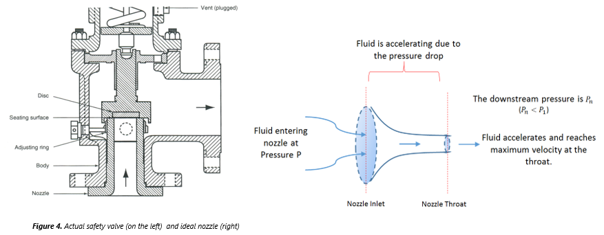
Many electronic, pneumatic and hydraulic systems exist today to control fluid system variables, such as pressure, temperature and flow. Each of these systems requires a power source of some type, such as electricity or compressed air in order to operate. A pressure Relief Valve must be capable of operating at all times, especially during a period of power failure when system controls are nonfunctional. The sole source of power for the pressure Relief Valve, therefore, is the process fluid.
Once a condition occurs that causes the pressure in a system or vessel to increase to a dangerous level, the pressure Relief Valve may be the only device remaining to prevent a catastrophic failure. Since reliability is directly related to the complexity of the device, it is important that the design of the pressure Relief Valve be as simple as possible.
The pressure Relief Valve must open at a predetermined set pressure, flow a rated capacity at a specified overpressure, and close when the system pressure has returned to a safe level. Pressure Relief Valves must be designed with materials compatible with many process fluids from simple air and water to the most corrosive media. They must also be designed to operate in a consistently smooth and stable manner on a variety of fluids and fluid phases.
The basic spring loaded pressure Relief Valve has been developed to meet the need for a simple, reliable, system actuated device to provide overpressure protection.
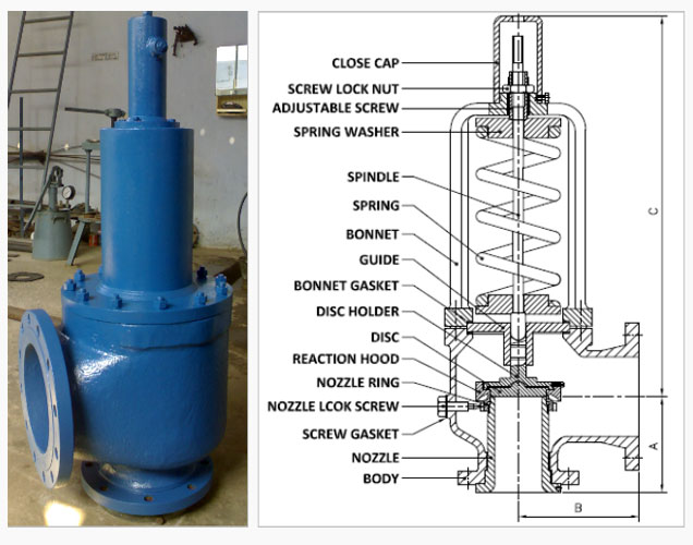
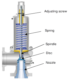
The Valve consists of a Valve inlet or nozzle mounted on the pressurized system, a disc held against the nozzle to prevent flow under normal system operating conditions, a spring to hold the disc closed, and a body/Bonnet to contain the operating elements. The spring load is adjustable to vary the pressure at which the Valve will open.
When a pressure Relief Valve begins to lift, the spring force increases. Thus system pressure must increase if lift is to continue. For this reason pressure Relief Valves are allowed an overpressure allowance to reach full lift. This allowable overpressure is generally 10% for Valves on unfired systems. This margin is relatively small and some means must be provided to assist in the lift effort.
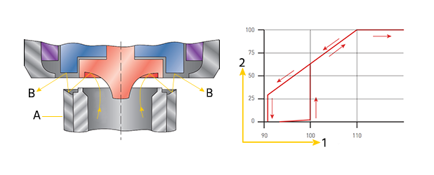
Most pressure Relief Valves, therefore, have a secondary control chamber or huddling chamber to enhance lift. As the disc begins to lift, fluid enters the control chamber exposing a larger area of the disc to system pressure.
This causes an incremental change in force which overcompensates for the increase in spring force and causes the Valve to open at a rapid rate. At the same time, the direction of the fluid flow is reversed and the momentum effect resulting from the change in flow direction further enhances lift. These effects combine to allow the Valve to achieve maximum lift and maximum flow within the allowable overpressure limits. Because of the larger disc area exposed to system pressure after the Valve achieves lift, the Valve will not close until system pressure has been reduced to some level below the set pressure. The design of the control chamber determines where the closing point will occur.
A safety Valve is a pressure Relief Valve actuated by inlet static pressure and characterized by rapid opening or pop action. (It is normally used for steam and air services.)
A low-lift safety Valve is a safety Valve in which the disc lifts automatically such that the actual discharge area is determined by the position of the disc.
A full-lift safety Valve is a safety Valve in which the disc lifts automatically such that the actual discharge area is not determined by the position of the disc.
A Relief Valve is a pressure relief device actuated by inlet static pressure having a gradual lift generally proportional to the increase in pressure over opening pressure. It may be provided with an enclosed spring housing suitable for closed discharge system application and is primarily used for liquid service.
A safety Relief Valve is a pressure Relief Valve characterized by rapid opening or pop action, or by opening in proportion to the increase in pressure over the opening pressure, depending on the application and may be used either for liquid or compressible fluid.
A conventional safety Relief Valve is a pressure Relief Valve which has its spring housing vented to the discharge side of the Valve. The operational characteristics (opening pressure, closing pressure, and relieving capacity) are directly affected by changes of the back pressure on the Valve.
A balanced safety Relief Valve is a pressure Relief Valve which incorporates means of minimizing the effect of back pressure on the operational characteristics (opening pressure, closing pressure, and relieving capacity).
A pilotoperated pressure Relief Valve is a pressure Relief Valve in which the major relieving device is combined with and is controlled by a self-actuated auxiliary pressure Relief Valve.
A poweractuated pressure Relief Valve is a pressure Relief Valve in which the major relieving device is combined with and controlled by a device requiring an external source of energy.
A temperature-actuated pressure Relief Valve is a pressure Relief Valve which may be actuated by external or internal temperature or by pressure on the inlet side.
A vacuum Relief Valve is a pressure relief device designed to admit fluid to prevent an excessive internal vacuum; it is designed to reclose and prevent further flow of fluid after normal conditions have been restored.
Many Codes and Standards are published throughout the world which address the design and application of pressure Relief Valves. The most widely used and recognized of these is the ASME Boiler and Pressure Vessel Code, commonly called the ASME Code.
is the calculated mass flow from an orifice having a cross sectional area equal to the flow area of the safety Valve without regard to flow losses of the Valve.
the pressure at which a Valve is set on a test rig using a test fluid at ambient temperature. This test pressure includes corrections for service conditions e.g. backpressure or high temperatures.
is the value of increasing static inlet pressure of a pressure Relief Valve at which there is a measurable lift, or at which the discharge becomes continuous as determined by seeing, feeling or hearing.
Because cleanliness is essential to the satisfactory operation and tightness of a safety Valve, precautions should be taken during storage to keep out all foreign materials. Inlet and outlet protectors should remain in place until the Valve is ready to be installed in the system. Take care to keep the Valve inlet absolutely clean. It is recommended that the Valve be stored indoors in the original shipping container away from dirt and other forms of contamination.
Safety Valves must be handled carefully and never subjected to shocks. Rough handling may alter the pressure setting, deform Valve parts and adversely affect seat tightness and Valve performance.
When it is necessary to use a hoist, the chain or sling should be placed around the Valve body and Bonnet in a manner that will insure that the Valve is in a vertical position to facilitate installation.
Many Valves are damaged when first placed in service because of failure to clean the connection properly when installed. Before installation, flange faces or threaded connections on both the Valve inlet and the vessel and/or line on which the Valve is mounted must be thoroughly cleaned of all dirt and foreign material.
Because foreign materials that pass into and through safety Valves can damage the Valve, the systems on which the Valves are tested and finally installed must also be inspected and cleaned. New systems in particular are prone to contain foreign objects that inadvertently get trapped during construction and will destroy the seating surface when the Valve opens. The system should be thoroughly cleaned before the safety Valve is installed.
The gaskets used must be dimensionally correct for the specific flanges. The inside diameters must fully clear the safety Valve inlet and outlet openings so that the gasket does not restrict flow.
For flanged Valves, draw down all connection studs or bolts evenly to avoid possible distortion of the Valve body. For threaded Valves, do not apply a wrench to the Valve body. Use the hex flats provided on the inlet bushing.
Safety Valves are intended to open and close within a narrow pressure range. Valve installations require accurate design both as to inlet and discharge piping. Refer to International, National and Industry Standards for guidelines.
The Valve should be mounted vertically in an upright position either directly on a nozzle from the pressure vessel or on a short connection fitting that provides a direct, unobstructed flow between the vessel and the Valve. Installing a safety Valve in other than this recommended position will adversely affect its operation.
Discharge piping should be simple and direct. A "broken" connection near the Valve outlet is preferred wherever possible. All discharge piping should be run as direct as is practicable to the point of final release for disposal. The Valve must discharge to a safe disposal area. Discharge piping must be drained properly to prevent the accumulation of liquids on the downstream side of the safety Valve.
The weight of the discharge piping should be carried by a separate support and be properly braced to withstand reactive thrust forces when the Valve relieves. The Valve should also be supported to withstand any swaying or system vibrations.
If the Valve is discharging into a pressurized system be sure the Valve is a "balanced" design. Pressure on the discharge of an "unbalanced" design will adversely affect the Valve performance and set pressure.
The Bonnets of balanced bellows safety Valves must always be vented to ensure proper functioning of the Valve and to provide a telltale in the event of a bellows failure. Do not plug these open vents. When the fluid is flammable, toxic or corrosive, the Bonnet vent should be piped to a safe location.
It is important to remember that a pressure Relief Valve is a safety device employed to protect pressure vessels or systems from catastrophic failure. With this in mind, the application of pressure Relief Valves should be assigned only to fully trained personnel and be in strict compliance with rules provided by the governing codes and standards.

Compressor Safety Valve of HFA42Y Series is a conventional full nozzle reaction type relief valve designed for low and medium set pressure of gas and liquid applications. Its set pressure range is <10.0 MPa, maximal working temperature <300 DegreeC, suitable for most LP line service. The material selection can be carbon steel or stainless steel, and for stainless steel, the valve is able to handle with corrosive medium for both gas and liquid states.
The surface of both disc and nozzle seat is deposited with hard alloy of Stellite, and the excellent surface treatment by precision machining and lapping ensure the tightness and stable performance during the operation.
Set pressure (open pressure), and this Compressor Safety Valve, shall be adjusted according to the max and min set pressure requirement, or comply with the requirements on custome"s request. Before leaving the factory, the set pressure shall be adjusted to the min open pressure, or comply with the requirements on customer"s request.
PACKING AND DELIVERYThe valves will be shipped individually packaged and identified with protective covering and coating for all climatic conditions to prevent mechanical damage or corrosion of components. The valves are to be shipped in an upright position.
The nozzle on the end of a fire hose is one of the most important pieces of equipment that a firefighter has at their disposal when combating a hostile fire. It"s the business end of what we do.
Understanding the nozzle involves more than knowing if a push or a pull opens the bale and if a left or right twist delivers a straight stream. Here are five nozzle questions whose answers you may not know or have forgotten. Either way, knowing your nozzle gives you an edge over your enemy in a fire attack.
Conventional fog nozzles have a fixed or selectable gpm setting. These settings correspond to a particular discharge orifice, or tip size. In order for a conventional nozzle with a fixed opening to operate at the correct nozzle pressure of 100 psi, the proper gpm flow must be supplied. For example, a selectable gallonage nozzle with settings of 30, 60, 95 and 125 gpm will only deliver those flows of 100 psi of nozzle pressure.
There are two possible results when the conventional nozzle is not supplied with the rated or selected flow. First, inadequate flow provides a weak, ineffective stream that fails to reach the seat of the fire. Second, too much water flow creates excessive nozzle pressure making the hose line more difficult to handle and potentially jeopardizing the safety of the nozzle crew.
With an automatic nozzle, the discharge orifice continually adjusts depending on the flow to the nozzle. This sets the flow being supplied to the proper nozzle pressure and correct velocity for maximum extinguishing capability.
The automatic nozzle uses a principle very similar to that of a pumper relief valve. A highly dependable spring, connected to the baffle that forms the discharge orifice, is balanced against the water pressure in the nozzle.
The pressure-control spring senses any increase or decrease in pressure within the nozzle. It then moves the baffle in or out to maintain a particular tip size necessary to keep the nozzle pressure at 100 psi. In effect, the nozzle is constantly changing tip size to match the water being supplied at that moment.
Automatic nozzles greatly simplify pump operation. Since automatic nozzles are designed to operate at 100 psi nozzle pressure, this becomes the minimum starting point for any operation.
The basic formula for calculating pump discharge pressure is PDP = NP + TPL — PDP is the pump discharge pressure, NP is the nozzle pressure and TPL is the total pressure loss (that"s hose line friction loss plus apparatus friction loss plus elevation pressure).
With an automatic, the nozzle pressure will remain constant and the formula can be rewritten as: PDP = 100 + TPL. So, for a 200-foot pre-connected 1 3/4-inch hose, what pump pressure will be required to flow 150 gpm? Friction loss in 1 3/4-inch hose for 150 gpm is about 28 psi per 100 feet of hose.
The advantage of using an automatic nozzle is that any flow can be delivered by the pump operator and still be controlled by the nozzle operator. Variable flow, constant nozzle pressure, and nozzleman flow control are three essential elements to successful fire streams and fire attack.
If the eductor manufacturer"s recommendations for inlet pressure, maximum hose length and size are followed, the automatic nozzle will adjust itself automatically to the rating of the eductor. With any eductor system, the nozzle valve must be fully open to prevent excessive back pressure on the eductor, which will prevent foam concentrate pickup.
Certain guidelines, however, must be followed. Foam-making is simply the addition of a proper amount of foam concentrate to water. This solution of foam concentrate and water is then mixed with air (aeration) either at the nozzle with aspirating attachments or as the stream pulls air along with it in a non-aspirating application.
Reducing nozzle pressure does account for some reduction in nozzle reaction. But how much reduction in pressure is required to get a significant reduction in reaction? And while reduced reaction may be a positive aspect, what are the negative aspects of choosing a low-pressure nozzle delivery system?
Those advocating for reducing the fog nozzle pressure typically would reduce the required nozzle pressure downward from 100 psi to 75 psi. If the flow is kept constant, the reaction reduction from a 25 percent cut in nozzle pressure is 13 percent. It works out this way: a 200 gpm stream at 100 psi has 101 pounds of reaction; cutting the nozzle pressure to 75 psi reduces the reaction to 88 pounds.
Nozzle pressure is directly related to the velocity of the stream. For the given example, instead of a stream speeding through the fire"s super-heated gases at 80 mph, it goes through at 60 mph. Which one goes farther? Which splashes more when it hits? Which bores through the wood char to get to deep-seated heat?
Farris’s pressure relief valves are designed to automatically protect your equipment against excessive overpressure. The Series 2600 pressure relief valves are designed to function equally well on air, gases, steam, or liquid service.
The pressure relief valve design incorporates several features which allow this valve to take a maximum amount of piping strain without hampering the functional characteristics of the valve or contributing to serious leakage.
The superior strength built into the body of the Farris pressure relief valve to resist these discharge piping strains materially reduces the deflection and distortion in the valve and reduces the leakage encountered, when at times, discharge piping strains become excessive.
The valve is engineered for exceptional tightness because of positive alignment, a high strength disc design, the elimination of thermal distortion and
It is a valve that is designed to detect and prevent changes in pressure which could lead to damage and failure in a number of applications. If the desired pressure is exceeded, the valve releases the excess pressure.


 8613371530291