
ari safety valve manual brands

ARI-SAFE Safety valve Full lift safety valve / Standard safety valve ARI-SAFE Full lift safety valve D/G Standard safety valve F • Type-test approved acc. to DIN EN ISO 4126 / AD2000-A2 • TÜV · SV · . . -663 · D/G Figure 901-912 • TÜV · SV · . . -663 · F Figure 901/911 • Further approvals: see inside ARI-SAFE Standard safety valve for the heating technology • Type-test approved acc. to TRD 721 • TÜV · SV · . . -688 · D/G/H Figure 903 • TÜV · SV · . . -688 · D Figure 904 ARI-SAFE-P Standard safety valve D/G/F • Type-test approved acc. to DIN EN ISO 4126 / AD2000-A2 • TÜV · SV · . . -811 · D/G Figure 921-924 • TÜV · SV · . . -811 · F Figure 921/923 ARI-SAFE-TC Full lift safety valve D/G Standard safety valve F • Type-test approved acc. to DIN EN ISO 4126 / AD2000-A2 • TÜV · SV · . . -995 · D/G Figure 941-943 • TÜV · SV · . . -995 · F Figure 941/943 ARI-SAFE-TC Standard safety valve for the heating technology • Type-test approved acc. to TRD 721 • TÜV · SV · . . -997 · D/G/H Figure 945 • TÜV · SV · . . -997 · D Figure 946 ARI-SAFE-TCP Standard safety valve D/G/F • Type-test approved acc. to DIN EN ISO 4126 / AD2000-A2 • TÜV · SV · . . -1041 · D/G Figure 961-963 • TÜV · SV · . . -1041 · F Figure 961/963 ARI-SAFE-TCS Standard safety valve D/G/F • Type-test approved acc. to DIN EN ISO 4126 / AD2000-A2 • TÜV · SV · . . -1041 · D/G Figure 951-953 • TÜV · SV · . . -1041 · F Figure 951/953 FOR HORIZONTAL APPLICATION Edition 11/12 - Data subject to alteration Features: • Direct loaded with spring • Wear resistant seat/disc • Precision disc alignment and guide • Possible with soft seal disc • Possible with EPDM bellow 953 • Possible with stainless steel bellow Page 28 • ARI-SAFE-TC/TCP/TCS: All common thread types Data sheet 900001 englisch (english)
Fig. 901 / 902 / 911 / 912 ARI-SAFE - Full lift safety valve D/G, Standard safety valve F Figure Nominal pressure Nominal diameter Temperature range Flange holes/thickness tolerances DIN 2533/2533 DIN 28607/28605 DIN 2545/2543 DIN 2545/2543 Type-test approval Full lift safety valve: TÜV · SV · . . -663 · D/G (Fig. 901/902/911/912) Standard safety valve: TÜV · SV · . . -663 · F (Fig. 901/911) Set gauge pressure refer to „Capacity“. Requirement Acc. to EN ISO 4126-1, VdTÜV-leaflet 100, AD2000-A2, TRD 421, material selection observe TRB 801 No. 45!! Construction Safety valve, spring loaded,...
Fig. 901 / 902 / 911 / 912 Dimensions and weights DN1/DN2 (mm) 20/32 18 d0 (mm) 254 A0 (mm2) 85 l (mm) 95 l1 (mm) 270 H (mm) 310 H (Bellow design) (mm) 150 X (mm) G 1/4“ Drainhole with plug 1) (inch) 8,5 Weight (kg) 9,5 Weight (Bellow design) (kg) Standard-flange dimensions refer to page 34. 1) Spring ranges: Standard design (barg) DN20 DN25 - 50 DN65 DN80 Spring ranges: Bellow design (barg) DN20 DN25 DN32 DN40 Design with bellow as standard valve (only Fig. 901/911) Description Body Seat Studs Spindle guide Hexagon nut Bonnet, closed 12 Disc unit 14 Spindle * 17 Adjusting screw 28 Cap,...
Capacity Fig. 901 / 911 Capacity water incl. 10% overpressure Gauge press. ← max. set pressure stainless steel version Certified coefficient of discharge Kdr (Values for D/G variable: DN20-100 < 3,5 bar, DN125-150 < 4,0 bar) Kdr D/G Edition 11/12 - Data subject to alteration
ARI-SAFE - Heating-safety valve Figure Nominal pressure Nominal diameter Temperature range Flange holes/thickness tolerances DIN 2533/2533 Type-test approval spring loaded: TÜV · SV · . . -688 · D/G/H Set gauge pressure refer to „Capacity“. Requirement Acc. to TRD 721 Part 6, material selection observe TRD! (EN-JL1040 max. 10 bar; >10 bar 25.903 EN-JS1049 or 35.903 1.0619+N) Application Acc. to DIN EN 12828 Heating systems in buildings Constructions Standard safety valve, spring loaded, direct loaded metal seat with EPDM insert, EPDM-bellow, closed spring bonnet with control hole, open...
Dimensions and weights DN1/DN2 (mm) 20/32 18 d0 (mm) 254 A0 (mm2) 85 l (mm) 95 l1 (mm) 270 H (mm) 150 X (mm) G 1/4“ Drainhole with plug (optional) (inch) 8,5 Weight (kg) Standard-flange dimensions refer to page 34. Parts Pos. Description 1 Body 2 Seat 3 Studs 4 Spindle guide 8 Hexagon nut 11 Bonnet, closed 12 Disc unit 14 Spindle * 17 Adjusting screw 29 Cap, open 37 Spring * 41 Lever, open 43 Bellow * Spare parts Information / restriction of technical rules need to be observed! ARI-Valves of EN-JL1040 are not allowed to be operated in systems acc. to TRD 110. A production allowance acc. to...
Capacity Fig. 903 Capacity water Water 20°C (kg/h) ^ Sizing: 1 l/h = 1 kW Sizing safety valves for the volume flow of water expansion (DIN 4751 p2 - item 8.1) Edition 11/12 - Data subject to alteration
ARI-SAFE - Low pressure steam - safety valve Figure Nominal pressure Nominal diameter Temperature range Flange holes/thickness tolerances DIN 2533/2533 Type-test approval Low pressure steam - safety valve: TÜV · SV · . . -688 · D Set gauge pressure refer to „Capacity“. Requirement Acc. to TRD 721 Part 5 Application For low pressure steamgenerators up to 1 bar, DIN 4750 and DIN EN 12828 Heating systems in buildings Construction Standard safety valve, spring loaded, direct loaded, EPDM-bellow, closed bonnet with control hole, open lifting device, stainless steel seat and spindle Sizing refer...

Valves Online Limited is a company registered in England. Registration number: 04994458. Registered office: Unit L3 Yelverton Business Park, Crapstone, Yelverton, Devon, United Kingdom, PL20 7PY.
We specialize in thermal heat transfer fluid (hot oil) valves, known in the ARI-Armaturen family as the FABA product line. These are commonly found anywhere heat transfer is required whether for the manufacture of engineered wood, chemicals, automobiles, coatings, fibers and non-woven textiles, asphalt, industrial cooking, and a host of other industries. Other ARI-Armaturen products are found in similar applications and industries, and we can assist you with these as well.

Direct Loaded Safety Valves for blowing off excess pressure of steam, vapor, gases, and liquid from pressure vessels, steam boiler, hot water boiler and piping systems. ARI-SAFE safety valves are available in full-stroke and normal versions.
Our safety valves are available with metal or soft seated plugs, with precise centering and guiding. Materials include cast iron, cast steel, and stainless steel. Call us for further options!

The ARI-REYCO line from ARI Armaturen features a range of direct spring acting safety relief valves for gas, liquid, and steam service. As a distributor for ARI-Armaturen, Cross company offers a variety of options to keep your operation safe and our team of experts have worked with customers in a wide range of process applications across multiple industries.
With such a variety of options available, finding the right solution is important. We can work with your team to determine the best product for your operation. Learn more about ARI-REYCO series safety relief valves below and Start a conversation with a Cross expert today!
*ARI-REYCO brand valves (and/or valve parts) are fully interchangeable with, and replaceable for, Lonergan valves (and/or valve parts). Londergan is a trademark of Pentair Valves and Controls. ARI-Reyco is not licensed to use the Lonergan trademark.

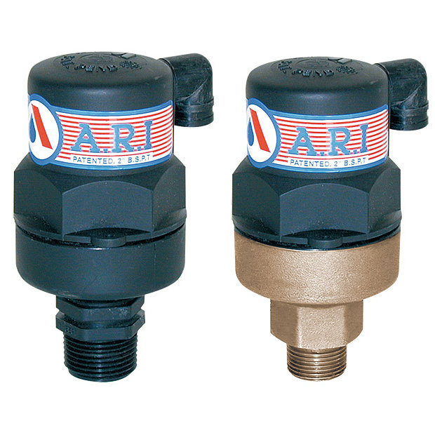
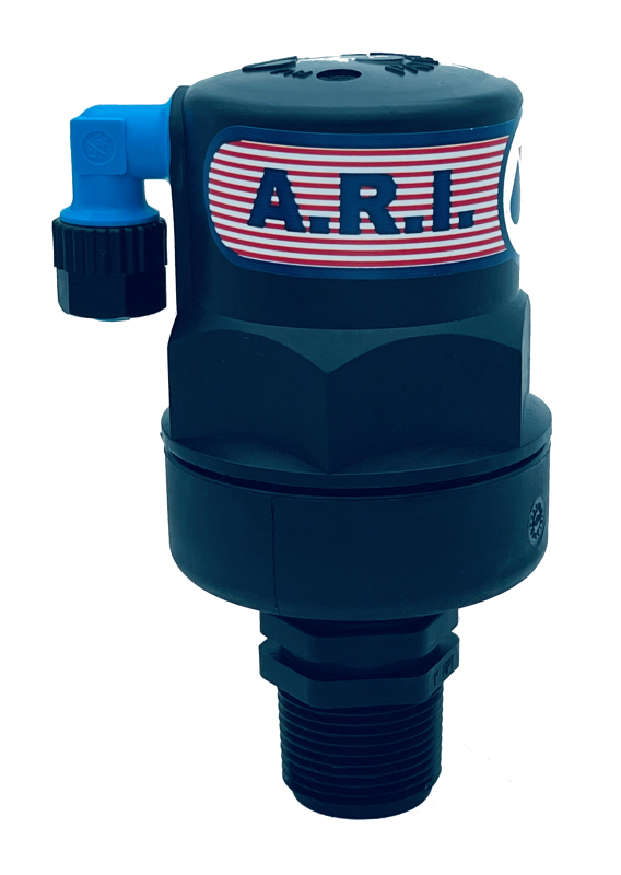
The valves are suitable for installation in waterworks systems for infrastructure applications and potable water distribution systems in high-rise buildings.
The A.R.I. W-40 Series is line of metal, seat-seal actuated hydraulic control valves which features a unique globe body with floating actuator and an elliptic shaped seat-seal.
The D-060 SB is a complete product package that combines the reliable and efficient properties of the D-060 Combination Air Valve with the added feature of a sub-surface valve.
The NR-010 check valve is compatible for installation in horizontal pumps or boosters for gardening and agriculture, to prevent the return flow of water to its source.
The A.R.I. Hydraulically Controlled Check Valve (HCCV) is a multipurpose damping device for pump discharge control. The valve functions as a one-directional Flow Control Valve.

ARI can look back on a tradition of more than seventy years as a partner for control, isolation, safety and steam trapping of liquid and gaseous media.

Originally known as J.E. Lonergan Valve Company of Philadelphia, Lonergan Valves has undergone a series of owners, but the original Lonergan safety relief valve SRV and pressure relief valve PRV have maintained their integrity. Ownership has gone from Pentair to Reyco, from Reyco to Tyco
The original product line included Navy valves, pressure gauges, steam whistles, oiling devices, water level gauges SRV’s and PRV’s, is now just safety relief valves SRV, and pressure relief valves PRV.
Original J.E. Lonergan Valve Company series model numbers: ABS, ABB, ACA, AAA, FBF, FBT, FBA, D, DB, DO, GIF, GBF, L14, JL14, L40, JL40, L41, DH, EIF, BBJ, LCT-14, LCT-40, DS, R, BBJ, BIA, BCA, BAS, YBJ, YIA, H, HK, HU, TBB, HCA, HSS, VAK, have now taken on new part numbers, but designs remain the same. There are also a series of interim numerical codes that have now been replaced. 11-H-200, 12-H-200, 13-H-200, 14-H-200, 23-H-200, 34-H-200, 41-H-200, 42-H-200, 44-H-200, 41-W-200, LCT-20, LCT-11, 11-W-200, 15-W, ARV, HDF, FSS, T, TR, TL, TLG, HRV, HRN, HRX, HTC, T-DP, 13-W, and 43-W. For Datasheets for these models, accurate detailed information is available in the form of pdf or an electronic data manual that contains individual technical data sheets to support the selection of valve.
When replacing a Lonergan Valve it is important to obtain inlet and outlet sizes, end connections, set pressure, coding requirements (for capacity of steam Lbs./hr, an air of gas cfm, or liquid, GPM values). Inlet and outlet flange class options are Class 150, 300, 600, 900, 1500, 2500, and 4500. If Ring Type Joint (RTJ) is required, please specify. Buttweld end or socket weld end connections must include bore schedules when generating an RFQ or order. They are available as standard, 40, 60, XH, 80, 100, 120, 140, 160, or XXH.
The Lonergan valve will also be embossed with a body material code. This can be represented as ASTM A126 Cast Iron, B62 Bronze, A105 Carbon Steel, ASTM A182, Grade F11, Grade F316 / F316L, Grade F22, Alloy 20, or Monel. The standard spring material is Chrome Vanadium
Safety relief valves, SRV, and pressure relief valves PRV, are manufactured in conformance to Section VIII of the ASME Boiler and Pressure Vessel Code for air, steam, and liquid service. Capacities certified by the National Board of Boiler and Pressure Vessel Inspectors. NACE Code valve certification included.
Please include Size and Model Number, or: Size, Valve Type, Body and Trim material, Pressure Class, end connections, and any special code requirements. Include set pressure, service media, and temperature, and required capacity, if any.
Lonergan Valve replacement parts are available for virtually every component of a valve assembly. Valve body, valve bonnet, replacement gasket kit, spring, nozzles, guides, discs, and spring steps, if identified by model number and size are normally stocked.

Curtiss-Wright"s selection of Pressure Relief Valves comes from its outstanding product brands Farris and Target Rock. We endeavor to support the whole life cycle of a facility and continuously provide custom products and technologies. Boasting a reputation for producing high quality, durable products, our collection of Pressure Relief Valves is guaranteed to provide effective and reliable pressure relief.
While some basic components and activations in relieving pressure may differ between the specific types of relief valves, each aims to be 100% effective in keeping your equipment running safely. Our current range includes numerous valve types, from flanged to spring-loaded, threaded to wireless, pilot operated, and much more.
A pressure relief valve is a type of safety valve designed to control the pressure in a vessel. It protects the system and keeps the people operating the device safely in an overpressure event or equipment failure.
A pressure relief valve is designed to withstand a maximum allowable working pressure (MAWP). Once an overpressure event occurs in the system, the pressure relief valve detects pressure beyond its design"s specified capability. The pressure relief valve would then discharge the pressurized fluid or gas to flow from an auxiliary passage out of the system.
Below is an example of one of our pilot operated pressure relief valves in action; the cutaway demonstrates when high pressure is released from the system.
Air pressure relief valves can be applied to a variety of environments and equipment. Pressure relief valves are a safety valve used to keep equipment and the operators safe too. They"re instrumental in applications where proper pressure levels are vital for correct and safe operation. Such as oil and gas, power generation like central heating systems, and multi-phase applications in refining and chemical processing.
At Curtiss-Wright, we provide a range of different pressure relief valves based on two primary operations – spring-loaded and pilot operated. Spring-loaded valves can either be conventional spring-loaded or balanced spring-loaded.
Spring-loaded valves are programmed to open and close via a spring mechanism. They open when the pressure reaches an unacceptable level to release the material inside the vessel. It closes automatically when the pressure is released, and it returns to an average operating level. Spring-loaded safety valves rely on the closing force applied by a spring onto the main seating area. They can also be controlled in numerous ways, such as a remote, control panel, and computer program.
Pilot-operated relief valves operate by combining the primary relieving device (main valve) with self-actuated auxiliary pressure relief valves, also known as the pilot control. This pilot control dictates the opening and closing of the main valve and responds to system pressure. System pressure is fed from the inlet into and through the pilot control and ultimately into the main valve"s dome. In normal operating conditions, system pressure will prevent the main valve from opening.
The valves allow media to flow from an auxiliary passage and out of the system once absolute pressure is reached, whether it is a maximum or minimum level.
When the pressure is below the maximum amount, the pressure differential is slightly positive on the piston"s dome size, which keeps the main valve in the closed position. When system pressure rises and reaches the set point, the pilot will cut off flow to the dome, causing depressurization in the piston"s dome side. The pressure differential has reversed, and the piston will rise, opening the main valve, relieving pressure.
When the process pressure decreases to a specific pressure, the pilot closes, the dome is repressurized, and the main valve closes. The main difference between spring-loaded PRVs and pilot-operated is that a pilot-operated safety valve uses pressure to keep the valve closed.
Pilot-operated relief valves are controlled by hand and are typically opened often through a wheel or similar component. The user opens the valve when the gauge signifies that the system pressure is at an unsafe level; once the valve has opened and the pressure has been released, the operator can shut it by hand again.
Increasing pressure helps to maintain the pilot"s seal. Once the setpoint has been reached, the valve opens. This reduces leakage and fugitive emissions.
At set pressure the valve snaps to full lift. This can be quite violent on large pipes with significant pressure. The pressure has to drop below the set pressure in order for the piston to reseat.
At Curtiss-Wright we also provide solutions for pressure relief valve monitoring. Historically, pressure relief valves have been difficult or impossible to monitor. Our SmartPRV features a 2600 Series pressure relief valve accessorized with a wireless position monitor that alerts plant operators during an overpressure event, including the time and duration.
There are many causes of overpressure, but the most common ones are typically blocked discharge in the system, gas blowby, and fire. Even proper inspection and maintenance will not eliminate the occurrence of leakages. An air pressure relief valve is the only way to ensure a safe environment for the device, its surroundings, and operators.
A PRV and PSV are interchangeable, but there is a difference between the two valves. A pressure release valve gradually opens when experiencing pressure, whereas a pressure safety valve opens suddenly when the pressure hits a certain level of over pressurization. Safety valves can be used manually and are typically used for a permanent shutdown. Air pressure relief valves are used for operational requirements, and they gently release the pressure before it hits the maximum high-pressure point and circulates it back into the system.
Pressure relief valves should be subject to an annual test, one per year. The operator is responsible for carrying out the test, which should be done using an air compressor. It’s imperative to ensure pressure relief valves maintain their effectiveness over time and are checked for signs of corrosion and loss of functionality. Air pressure relief valves should also be checked before their installation, after each fire event, and regularly as decided by the operators.
Direct-acting solenoid valves have a direct connection with the opening and closing armature, whereas pilot-operated valves use of the process fluid to assist in piloting the operation of the valve.
A control valve works by varying the rate of fluid passing through the valve itself. As the valve stem moves, it alters the size of the passage and increases, decreases or holds steady the flow. The opening and closing of the valve is altered whenever the controlled process parameter does not reach the set point.
Control valves are usually at floor level or easily accessible via platforms. They are also located on the same equipment or pipeline as the measurement and downstream or flow measurements.
An industrial relief valve is designed to control or limit surges of pressure in a system, most often in fluid or compressed air system valves. It does so as a form of protection for the system and defending against instrument or equipment failure. They are usually present in clean water industries.
A PRV is often referred to as a pressure relief valve, which is also known as a PSV or pressure safety valve. They are used interchangeably throughout the industry depending on company standards.
INSPECTION & MAINTENANCE BULLETIN ARI 1108 & HP1108 Safety Relief Valve These instructions are applicable to the following models: ARI 1108 ARI HP1108 Only facilities with AAR Activity Code C5 are certified to recondition, repair, retest and qualify tank car safety relief valves. Personnel performing inspection and test must be certified Level I per AAR Manual of Standards and Recommended Practices, M-1002, Appendix T, 1.4.3.
New Valves for Replacement of Existing Equipment New valves are tested, sealed and packaged at the time of manufacture. A new valve can be applied provided it is still in its original packaging and tested within 6 months of the installation date. A valve with a test date older than 6 months must have the O-rings replaced and retested.
The inside of the top stem guide should be free of paint, debris, nicks, burrs or other discontinuities. Visually inspect the inside of the guide and the mating area on the upper stem. Any sign of significant wear should be reported to ARI Engineering for review and disposition. Valve Stem Remove all scale, residue and other foreign material from the stem with a wire brush.
Valve Body The area around the valve seat must be free of debris, corrosion and foreign objects. Cleaning can be accomplished with a light brush off blast using glass bead media. The seating surface must be free of nicks, burrs and gouges. The area should be cleaned and lightly polished with 400 grit emery cloth. Any discontinuity that would prevent the valve from sealing is grounds for replacement.
The ARI 1108 safety relief valve is designed to operate at 75 psig. The start-to-discharge pressure (STD) must be 75 psig +/- 3 psig and vapor-tight at 60 psig minimum. The ARI HP1108 safety relief valve is designed to operate in a range from 225 psig to 330 psig. The start-to-discharge pressures (STD) are as follows:...
The undertaking of repair or replacement by the Purchaser, or its agents, without the expressed written consent of American Railcar Industries, Inc. (ARI) shall void ARI’ s warranty and relieve ARI of all responsibility. Under no circumstances shall ARI be liable for any direct, incidental, consequential or other damages of any kind in connection with the installation, operation, maintenance, repair, inspection or other use of any product purchased from it.


 8613371530291