
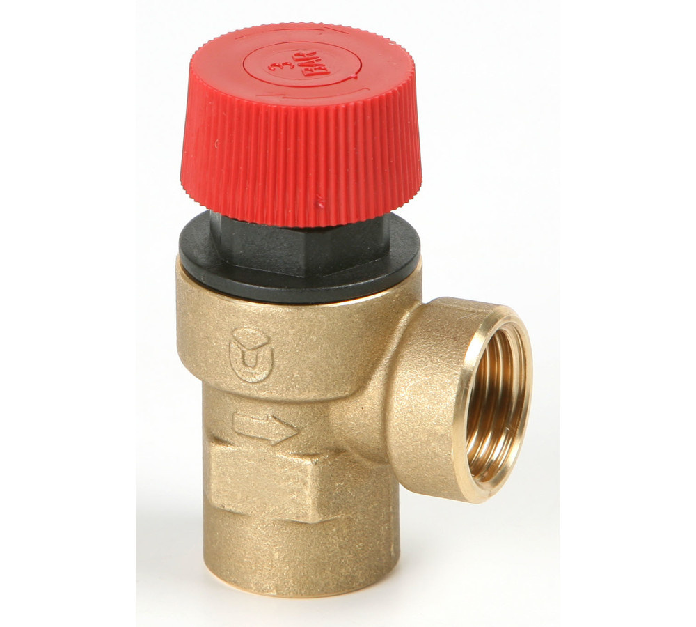
3 bar safety valve free sample
A safety valve must always be sized and able to vent any source of steam so that the pressure within the protected apparatus cannot exceed the maximum allowable accumulated pressure (MAAP). This not only means that the valve has to be positioned correctly, but that it is also correctly set. The safety valve must then also be sized correctly, enabling it to pass the required amount of steam at the required pressure under all possible fault conditions.
Once the type of safety valve has been established, along with its set pressure and its position in the system, it is necessary to calculate the required discharge capacity of the valve. Once this is known, the required orifice area and nominal size can be determined using the manufacturer’s specifications.
In order to establish the maximum capacity required, the potential flow through all the relevant branches, upstream of the valve, need to be considered.
In applications where there is more than one possible flow path, the sizing of the safety valve becomes more complicated, as there may be a number of alternative methods of determining its size. Where more than one potential flow path exists, the following alternatives should be considered:
This choice is determined by the risk of two or more devices failing simultaneously. If there is the slightest chance that this may occur, the valve must be sized to allow the combined flows of the failed devices to be discharged. However, where the risk is negligible, cost advantages may dictate that the valve should only be sized on the highest fault flow. The choice of method ultimately lies with the company responsible for insuring the plant.
For example, consider the pressure vessel and automatic pump-trap (APT) system as shown in Figure 9.4.1. The unlikely situation is that both the APT and pressure reducing valve (PRV ‘A’) could fail simultaneously. The discharge capacity of safety valve ‘A’ would either be the fault load of the largest PRV, or alternatively, the combined fault load of both the APT and PRV ‘A’.
This document recommends that where multiple flow paths exist, any relevant safety valve should, at all times, be sized on the possibility that relevant upstream pressure control valves may fail simultaneously.
The supply pressure of this system (Figure 9.4.2) is limited by an upstream safety valve with a set pressure of 11.6 bar g. The fault flow through the PRV can be determined using the steam mass flow equation (Equation 3.21.2):
Once the fault load has been determined, it is usually sufficient to size the safety valve using the manufacturer’s capacity charts. A typical example of a capacity chart is shown in Figure 9.4.3. By knowing the required set pressure and discharge capacity, it is possible to select a suitable nominal size. In this example, the set pressure is 4 bar g and the fault flow is 953 kg/h. A DN32/50 safety valve is required with a capacity of 1 284 kg/h.
Coefficients of discharge are specific to any particular safety valve range and will be approved by the manufacturer. If the valve is independently approved, it is given a ‘certified coefficient of discharge’.
This figure is often derated by further multiplying it by a safety factor 0.9, to give a derated coefficient of discharge. Derated coefficient of discharge is termed Kdr= Kd x 0.9
Critical and sub-critical flow - the flow of gas or vapour through an orifice, such as the flow area of a safety valve, increases as the downstream pressure is decreased. This holds true until the critical pressure is reached, and critical flow is achieved. At this point, any further decrease in the downstream pressure will not result in any further increase in flow.
A relationship (called the critical pressure ratio) exists between the critical pressure and the actual relieving pressure, and, for gases flowing through safety valves, is shown by Equation 9.4.2.
For steam, although ‘k’ is an isentropic coefficient, it is not actually the ratio of cp : c. As an approximation for saturated steam, ‘k’ can be taken as 1.135, and superheated steam, as 1.3. As a guide, for saturated steam, critical pressure is taken as 58% of accumulated inlet pressure in absolute terms.
Overpressure - Before sizing, the design overpressure of the valve must be established. It is not permitted to calculate the capacity of the valve at a lower overpressure than that at which the coefficient of discharge was established. It is however, permitted to use a higher overpressure (see Table 9.2.1, Module 9.2, for typical overpressure values). For DIN type full lift (Vollhub) valves, the design lift must be achieved at 5% overpressure, but for sizing purposes, an overpressure value of 10% may be used.
For liquid applications, the overpressure is 10% according to AD-Merkblatt A2, DIN 3320, TRD 421 and ASME, but for non-certified ASME valves, it is quite common for a figure of 25% to be used.
Backpressure - The sizing calculations in the AD-Merkblatt A2, DIN 3320 and TRD 421 standards account for backpressure in the outflow function,(Ψ), which includes a backpressure correction.
Two-phase flow - When sizing safety valves for boiling liquids (e.g. hot water) consideration must be given to vaporisation (flashing) during discharge. It is assumed that the medium is in liquid state when the safety valve is closed and that, when the safety valve opens, part of the liquid vaporises due to the drop in pressure through the safety valve. The resulting flow is referred to as two-phase flow.
The required flow area has to be calculated for the liquid and vapour components of the discharged fluid. The sum of these two areas is then used to select the appropriate orifice size from the chosen valve range. (see Example 9.4.3)
In order to ensure that the maximum allowable accumulation pressure of any system or apparatus protected by a safety valve is never exceeded, careful consideration of the safety valve’s position in the system has to be made. As there is such a wide range of applications, there is no absolute rule as to where the valve should be positioned and therefore, every application needs to be treated separately.
A common steam application for a safety valve is to protect process equipment supplied from a pressure reducing station. Two possible arrangements are shown in Figure 9.3.3.
The safety valve can be fitted within the pressure reducing station itself, that is, before the downstream stop valve, as in Figure 9.3.3 (a), or further downstream, nearer the apparatus as in Figure 9.3.3 (b). Fitting the safety valve before the downstream stop valve has the following advantages:
• The safety valve can be tested in-line by shutting down the downstream stop valve without the chance of downstream apparatus being over pressurised, should the safety valve fail under test.
• When setting the PRV under no-load conditions, the operation of the safety valve can be observed, as this condition is most likely to cause ‘simmer’. If this should occur, the PRV pressure can be adjusted to below the safety valve reseat pressure.
Indeed, a separate safety valve may have to be fitted on the inlet to each downstream piece of apparatus, when the PRV supplies several such pieces of apparatus.
• If supplying one piece of apparatus, which has a MAWP pressure less than the PRV supply pressure, the apparatus must be fitted with a safety valve, preferably close-coupled to its steam inlet connection.
• If a PRV is supplying more than one apparatus and the MAWP of any item is less than the PRV supply pressure, either the PRV station must be fitted with a safety valve set at the lowest possible MAWP of the connected apparatus, or each item of affected apparatus must be fitted with a safety valve.
• The safety valve must be located so that the pressure cannot accumulate in the apparatus viaanother route, for example, from a separate steam line or a bypass line.
It could be argued that every installation deserves special consideration when it comes to safety, but the following applications and situations are a little unusual and worth considering:
• Fire - Any pressure vessel should be protected from overpressure in the event of fire. Although a safety valve mounted for operational protection may also offer protection under fire conditions,such cases require special consideration, which is beyond the scope of this text.
• Exothermic applications - These must be fitted with a safety valve close-coupled to the apparatus steam inlet or the body direct. No alternative applies.
• Safety valves used as warning devices - Sometimes, safety valves are fitted to systems as warning devices. They are not required to relieve fault loads but to warn of pressures increasing above normal working pressures for operational reasons only. In these instances, safety valves are set at the warning pressure and only need to be of minimum size. If there is any danger of systems fitted with such a safety valve exceeding their maximum allowable working pressure, they must be protected by additional safety valves in the usual way.
In order to illustrate the importance of the positioning of a safety valve, consider an automatic pump trap (see Block 14) used to remove condensate from a heating vessel. The automatic pump trap (APT), incorporates a mechanical type pump, which uses the motive force of steam to pump the condensate through the return system. The position of the safety valve will depend on the MAWP of the APT and its required motive inlet pressure.
This arrangement is suitable if the pump-trap motive pressure is less than 1.6 bar g (safety valve set pressure of 2 bar g less 0.3 bar blowdown and a 0.1 bar shut-off margin). Since the MAWP of both the APT and the vessel are greater than the safety valve set pressure, a single safety valve would provide suitable protection for the system.
However, if the pump-trap motive pressure had to be greater than 1.6 bar g, the APT supply would have to be taken from the high pressure side of the PRV, and reduced to a more appropriate pressure, but still less than the 4.5 bar g MAWP of the APT. The arrangement shown in Figure 9.3.5 would be suitable in this situation.
Here, two separate PRV stations are used each with its own safety valve. If the APT internals failed and steam at 4 bar g passed through the APT and into the vessel, safety valve ‘A’ would relieve this pressure and protect the vessel. Safety valve ‘B’ would not lift as the pressure in the APT is still acceptable and below its set pressure.
It should be noted that safety valve ‘A’ is positioned on the downstream side of the temperature control valve; this is done for both safety and operational reasons:
Operation - There is less chance of safety valve ‘A’ simmering during operation in this position,as the pressure is typically lower after the control valve than before it.
Also, note that if the MAWP of the pump-trap were greater than the pressure upstream of PRV ‘A’, it would be permissible to omit safety valve ‘B’ from the system, but safety valve ‘A’ must be sized to take into account the total fault flow through PRV ‘B’ as well as through PRV ‘A’.
A pharmaceutical factory has twelve jacketed pans on the same production floor, all rated with the same MAWP. Where would the safety valve be positioned?
One solution would be to install a safety valve on the inlet to each pan (Figure 9.3.6). In this instance, each safety valve would have to be sized to pass the entire load, in case the PRV failed open whilst the other eleven pans were shut down.
If additional apparatus with a lower MAWP than the pans (for example, a shell and tube heat exchanger) were to be included in the system, it would be necessary to fit an additional safety valve. This safety valve would be set to an appropriate lower set pressure and sized to pass the fault flow through the temperature control valve (see Figure 9.3.8).
The primary purpose of a safety valve is to protect life, property and the environment. Safety valves are designed to open and release excess pressure from vessels or equipment and then close again.
The function of safety valves differs depending on the load or main type of the valve. The main types of safety valves are spring-loaded, weight-loaded and controlled safety valves.
Regardless of the type or load, safety valves are set to a specific set pressure at which the medium is discharged in a controlled manner, thus preventing overpressure of the equipment. In dependence of several parameters such as the contained medium, the set pressure is individual for each safety application.

Safety valves and pressure relief valves are crucial for one main reason: safety. This means safety for the plant and equipment as well as safety for plant personnel and the surrounding environment.
Safety valves and pressure relief valves protect vessels, piping systems, and equipment from overpressure, which, if unchecked, can not only damage a system but potentially cause an explosion. Because these valves play such an important role, it’s absolutely essential that the right valve is used every time.
The valve size must correspond to the size of the inlet and discharge piping. The National Board specifies that the both the inlet piping and the discharge piping connected to the valve must be at least as large as the inlet/discharge opening on the valve itself.
The connection types are also important. For example, is the connection male or female? Flanged? All of these factors help determine which valve to use.
The set pressure of the valve must not exceed the maximum allowable working pressure (MAWP) of the boiler or other vessel. What this means is that the valve must open at or below the MAWP of the equipment. In turn, the MAWP of the equipment should be at least 10% greater than the highest expected operating pressure under normal circumstances.
Temperature affects the volume and viscosity of the gas or liquid flowing through the system. Temperature also helps determine the ideal material of construction for the valve. For example, steel valves can handle higher operating temperatures than valves made of either bronze or iron. Both the operating and the relieving temperature must be taken into account.
Back pressure, which may be constant or variable, is pressure on the outlet side of the pressure relief valve as a result of the pressure in the discharge system. It can affect the set pressure of the upstream valve and cause it to pop open repeatedly, which can damage the valve.
For installations with variable back pressure, valves should be selected so that the back pressure doesn’t exceed 10% of the valve set pressure. For installations with high levels of constant back pressure, a bellows-sealed valve or pilot-operated valve may be required.
Different types of service (steam, air, gas, etc.) require different valves. In addition, the valve material of construction needs to be appropriate for the service. For example, valves made of stainless steel are preferable for corrosive media.
Safety valves and relief valves must be able to relieve pressure at a certain capacity. The required capacity is determined by several factors including the geometry of the valve, the temperature of the media, and the relief discharge area.
These are just the basic factors that must be considered when selecting and sizing safety valves and relief valves. You must also consider the physical dimensions of the equipment and the plant, as well as other factors related to the environment in which the valve will operate.

Two hands safety valve, which allows a safety use of two hands pneumatic controls (for example two push-button 3/2 N.C. to a certain distance) excluding false signals ...
... -start valve with Series MX2 air treatment units without the need for additional connection interfaces. The soft-start valve is positioned upstream of the safety valves, ...
The S50 Safety Shut Off valve is mainly used to avoid any damage to components as well as to avoid too high or too low pressure in the gas train. This could cause high financial losses and/or injured ...
The S100 Safety Shut Off valve is mainly used to avoid any damage to components as well as to avoid too high or too low pressure in the gas train. This could cause high financial losses and/or injured ...
The main purpose of the safety relief valve SL 5 is to relieve small pressure increases and quantities in the controlled system to prevent the safety shut-off valve from ...
Material: Body- CF8M; Valve Seat- CF8M Métal Seat, PTFE Soft Seat available Orifice Size: fc"(15mm), 3/4M(20mm), l"(25mm), l1/4,’(32mm)I ltë”(40mm), ...
PVS type slam shut valves are pilot-operated relief valves in which the opening and the closing of the main plug is controlled by a pilot device which is very ...
130 Series Safety valves are also available as Relief valves. Relief valves, identified by the letter R after the type number, are devices with an operational function, ...
Cryogenic Safety Valves Type 06011 is made with stainless steel. It is provided as a safety device for protection against thermal expansion in pipework and parts of facilities. ...


 8613371530291