
adjustable safety valve free sample
Standard W60 Adapter:The ‘standard’ adaptor is used on all models of short and long stroke W60 Series valves. Machined from SS 316L bar with a thick cross-section, the adaptor adds strength to the valve body and provides alignment for the stem. The outer perimeter seals to the valve body with an o-ring that is located forward to the product zone to minimize crevices. The product stem passes through the adaptor and is sealed to the adaptor with an o-ring. A Teflon® bearing guides the stem and takes up the mechanical loading imparted by hydraulic forces. This increases the service life of the stem seal. Adaptors are made in 1"-6" (25mm -152mm) sizes.
W80 Adapter: This adaptor is used to convert a ‘standard’ W60 series valve to a W80. The outer perimeter seals to the valve body with an o-ring that is located forward to the product zone to minimize crevices. The product stem passes through the adaptor and is sealed in the upper part and the lower part of the adaptor with o-rings. The space between the o-rings is flushed with a suitable liquid or steam. The Teflon® bearing is located in the flushed chamber. Adaptors are made in 1"-6" (25mm - 152mm) sizes. For vacuum-rated, extended shelf-life (ESL) applications, the W80A adaptor adds steam trace to the adapter-to-valve body connection.
Wiping Stem Seal Adapter: For high-risk and hard to clean product applications, the wiping stem seal fills the gap between the product zone and the traditional o-ring stem seal. The adaptor is a two-piece design to allow easy inspection or replacement of the wiping stem seal. The outer perimeter seals to the valve body with an o-ring that is located forward to the product zone to minimize crevices. A Teflon® bearing is used to guide and support the valve stem.

This direct-acting adjustable relief valve limits pressure at port 1 (on bottom of valve), by relieving to port 2 (on side of valve) when the relief pressure is reached. This valve is typically installed to limit pressure on the outlet of a pump or to limit pressure going to a hydraulic cylinder or motor. This relief pressure is preset at 1800 PSI when shipped. The valve has a minimum pressure of 400 PSI and a maximum pressure of 3000 PSI.

This pilot-operated adjustable pressure relief valve limits the pressure at port 1 (on bottom of valve) by relieving pressure at port 2 (on side of valve) when relief pressure is reached. This valve is typically installed to limit pressure on the outlet of a pump or to limit pressure going to a hydraulic cylinder or motor. This relief pressure is preset at 1800 PSI when shipped. The valve has a minimum pressure of 400 PSI and a maximum pressure of 3000 PSI.
Besides the P/T value of the sleeve the limitations of the valve bodies also have to be considered. Please refer to the EN 12516-1 resp. ASME B16.34 in order to choose a proper pressure rating (PN/class). The shown values refer to austenitic stainless steel 1.4408 (A351 Gr. CF8M).

Hydraulic and pneumatic systems must regulate air or liquid pressure according to a constant pressure threshold. If the pressure exceeds the set level, it can damage equipment and create a safety hazard for workers. Pressure relief valves regulate pressure levels to prevent these dangers.
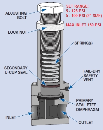
Pressure relief valves (PRVs), or back pressure regulators, reduce system pressure when it exceeds a maximum threshold. PRVs can also reduce pressure peaks that could damage equipment elsewhere in the facility. The main components of a pressure relief valve are:
When the pressure in the hose or pipe exceeds the pressure limit, will push against the diaphragm, compress the spring and open the valve. The valve opens and closes to maintain the specified pressure level. When the pressure dips below the accepted threshold, the valve closes. With adjustable PRVs, operators can adjust the spring mechanism to collapse under a higher or lower amount of pressure.
Enhances safety: PRVs were invented as a result of boilers exploding when they were not properly monitored. Thus, they are an easy and effective way to keep your system safe.
Increases efficiency: Relief valves automatically reclose when the pressure lowers to the set level, preventing excess loss of expensive gases from the system.
Materials: Most valves are made of plastic, brass, aluminum, or stainless steel. Weigh each material’s compatibility, advantages, and disadvantages relative to your system’s needs.
Operating temperature: Make sure the valve you choose can handle the expected operating temperature of your application, as the temperature can affect flow capacity and the responsiveness of the spring mechanism.
Air Logic designs and manufactures industrial pneumatic and vacuum control equipment, including preset and adjustable relief valves for medical and other applications. Our adjustable relief valves can be equipped with straight or barbed fittings. Single barbed models work best with exhaust ports that do not need a barb.
We also offer preset options, which we produce by presetting an adjustable valve at the desired pressure level. We test the valve for effectiveness before shipping it to you. Our ISO 9001:2015 certification ensures high-quality, reliable products with every delivery.

Relief valves open the input port to the exhaust port when a specific pressure differential (ie. setpoint) is achieved. A diaphragm provides area for pressure supplied from the input port to act against the spring force. When the force of the input pressure exceeds the spring force, the valve opens. The valve stays open until the input pressure drops below the setpoint.

In order to ensure that the maximum allowable accumulation pressure of any system or apparatus protected by a safety valve is never exceeded, careful consideration of the safety valve’s position in the system has to be made. As there is such a wide range of applications, there is no absolute rule as to where the valve should be positioned and therefore, every application needs to be treated separately.
A common steam application for a safety valve is to protect process equipment supplied from a pressure reducing station. Two possible arrangements are shown in Figure 9.3.3.
The safety valve can be fitted within the pressure reducing station itself, that is, before the downstream stop valve, as in Figure 9.3.3 (a), or further downstream, nearer the apparatus as in Figure 9.3.3 (b). Fitting the safety valve before the downstream stop valve has the following advantages:
• The safety valve can be tested in-line by shutting down the downstream stop valve without the chance of downstream apparatus being over pressurised, should the safety valve fail under test.
• When setting the PRV under no-load conditions, the operation of the safety valve can be observed, as this condition is most likely to cause ‘simmer’. If this should occur, the PRV pressure can be adjusted to below the safety valve reseat pressure.
Indeed, a separate safety valve may have to be fitted on the inlet to each downstream piece of apparatus, when the PRV supplies several such pieces of apparatus.
• If supplying one piece of apparatus, which has a MAWP pressure less than the PRV supply pressure, the apparatus must be fitted with a safety valve, preferably close-coupled to its steam inlet connection.
• If a PRV is supplying more than one apparatus and the MAWP of any item is less than the PRV supply pressure, either the PRV station must be fitted with a safety valve set at the lowest possible MAWP of the connected apparatus, or each item of affected apparatus must be fitted with a safety valve.
• The safety valve must be located so that the pressure cannot accumulate in the apparatus viaanother route, for example, from a separate steam line or a bypass line.
It could be argued that every installation deserves special consideration when it comes to safety, but the following applications and situations are a little unusual and worth considering:
• Fire - Any pressure vessel should be protected from overpressure in the event of fire. Although a safety valve mounted for operational protection may also offer protection under fire conditions,such cases require special consideration, which is beyond the scope of this text.
• Exothermic applications - These must be fitted with a safety valve close-coupled to the apparatus steam inlet or the body direct. No alternative applies.
• Safety valves used as warning devices - Sometimes, safety valves are fitted to systems as warning devices. They are not required to relieve fault loads but to warn of pressures increasing above normal working pressures for operational reasons only. In these instances, safety valves are set at the warning pressure and only need to be of minimum size. If there is any danger of systems fitted with such a safety valve exceeding their maximum allowable working pressure, they must be protected by additional safety valves in the usual way.
In order to illustrate the importance of the positioning of a safety valve, consider an automatic pump trap (see Block 14) used to remove condensate from a heating vessel. The automatic pump trap (APT), incorporates a mechanical type pump, which uses the motive force of steam to pump the condensate through the return system. The position of the safety valve will depend on the MAWP of the APT and its required motive inlet pressure.
This arrangement is suitable if the pump-trap motive pressure is less than 1.6 bar g (safety valve set pressure of 2 bar g less 0.3 bar blowdown and a 0.1 bar shut-off margin). Since the MAWP of both the APT and the vessel are greater than the safety valve set pressure, a single safety valve would provide suitable protection for the system.
Here, two separate PRV stations are used each with its own safety valve. If the APT internals failed and steam at 4 bar g passed through the APT and into the vessel, safety valve ‘A’ would relieve this pressure and protect the vessel. Safety valve ‘B’ would not lift as the pressure in the APT is still acceptable and below its set pressure.
It should be noted that safety valve ‘A’ is positioned on the downstream side of the temperature control valve; this is done for both safety and operational reasons:
Operation - There is less chance of safety valve ‘A’ simmering during operation in this position,as the pressure is typically lower after the control valve than before it.
Also, note that if the MAWP of the pump-trap were greater than the pressure upstream of PRV ‘A’, it would be permissible to omit safety valve ‘B’ from the system, but safety valve ‘A’ must be sized to take into account the total fault flow through PRV ‘B’ as well as through PRV ‘A’.
A pharmaceutical factory has twelve jacketed pans on the same production floor, all rated with the same MAWP. Where would the safety valve be positioned?
One solution would be to install a safety valve on the inlet to each pan (Figure 9.3.6). In this instance, each safety valve would have to be sized to pass the entire load, in case the PRV failed open whilst the other eleven pans were shut down.
If additional apparatus with a lower MAWP than the pans (for example, a shell and tube heat exchanger) were to be included in the system, it would be necessary to fit an additional safety valve. This safety valve would be set to an appropriate lower set pressure and sized to pass the fault flow through the temperature control valve (see Figure 9.3.8).

Safety valves and pressure relief valves are crucial for one main reason: safety. This means safety for the plant and equipment as well as safety for plant personnel and the surrounding environment.
Safety valves and pressure relief valves protect vessels, piping systems, and equipment from overpressure, which, if unchecked, can not only damage a system but potentially cause an explosion. Because these valves play such an important role, it’s absolutely essential that the right valve is used every time.
The valve size must correspond to the size of the inlet and discharge piping. The National Board specifies that the both the inlet piping and the discharge piping connected to the valve must be at least as large as the inlet/discharge opening on the valve itself.
The connection types are also important. For example, is the connection male or female? Flanged? All of these factors help determine which valve to use.
The set pressure of the valve must not exceed the maximum allowable working pressure (MAWP) of the boiler or other vessel. What this means is that the valve must open at or below the MAWP of the equipment. In turn, the MAWP of the equipment should be at least 10% greater than the highest expected operating pressure under normal circumstances.
Temperature affects the volume and viscosity of the gas or liquid flowing through the system. Temperature also helps determine the ideal material of construction for the valve. For example, steel valves can handle higher operating temperatures than valves made of either bronze or iron. Both the operating and the relieving temperature must be taken into account.
Back pressure, which may be constant or variable, is pressure on the outlet side of the pressure relief valve as a result of the pressure in the discharge system. It can affect the set pressure of the upstream valve and cause it to pop open repeatedly, which can damage the valve.
For installations with variable back pressure, valves should be selected so that the back pressure doesn’t exceed 10% of the valve set pressure. For installations with high levels of constant back pressure, a bellows-sealed valve or pilot-operated valve may be required.
Different types of service (steam, air, gas, etc.) require different valves. In addition, the valve material of construction needs to be appropriate for the service. For example, valves made of stainless steel are preferable for corrosive media.
Safety valves and relief valves must be able to relieve pressure at a certain capacity. The required capacity is determined by several factors including the geometry of the valve, the temperature of the media, and the relief discharge area.
These are just the basic factors that must be considered when selecting and sizing safety valves and relief valves. You must also consider the physical dimensions of the equipment and the plant, as well as other factors related to the environment in which the valve will operate.

Safety is of the utmost importance when dealing with pressure relief valves. The valve is designed to limit system pressure, and it is critical that they remain in working order to prevent an explosion. Explosions have caused far too much damage in companies over the years, and though pressurized tanks and vessels are equipped with pressure relief vales to enhance safety, they can fail and result in disaster.
That’s also why knowing the correct way to test the valves is important. Ongoing maintenance and periodic testing of pressurized tanks and vessels and their pressure relief valves keeps them in working order and keep employees and their work environments safe. Pressure relief valves must be in good condition in order to automatically lower tank and vessel pressure; working valves open slowly when the pressure gets high enough to exceed the pressure threshold and then closes slowly until the unit reaches the low, safe threshold. To ensure the pressure relief valve is in good working condition, employees must follow best practices for testing them including:
If you consider testing pressure relief valves a maintenance task, you’ll be more likely to carry out regular testing and ensure the safety of your organization and the longevity of your
It’s important to note, however, that the American Society of Mechanical Engineers (ASME) and National Board Inspection Code (NBIC), as well as state and local jurisdictions, may set requirements for testing frequency. Companies are responsible for checking with these organizations to become familiar with the testing requirements. Consider the following NBIC recommendations on the frequency for testing relief valves:
High-temperature hot water boilers (greater than 160 psi and/or 250 degrees Fahrenheit) – pressure test annually to verify nameplate set pressure. For safety reasons, removal and testing on a test bench is recommended
When testing the pressure relief valve, raise and lower the test lever several times. The lever will come away from the brass stem and allow hot water to come out of the end of the drainpipe. The water should flow through the pipe, and then you should turn down the pressure to stop the leak, replace the lever, and then increase the pressure.
One of the most common problems you can address with regular testing is the buildup of mineral salt, rust, and corrosion. When buildup occurs, the valve will become non-operational; the result can be an explosion. Regular testing helps you discover these issues sooner so you can combat them and keep your boiler and valve functioning properly. If no water flows through the pipe, or if there is a trickle instead of a rush of water, look for debris that is preventing the valve from seating properly. You may be able to operate the test lever a few times to correct the issue. You will need to replace the valve if this test fails.
When testing relief valves, keep in mind that they have two basic functions. First, they will pop off when the pressure exceeds its safety threshold. The valve will pop off and open to exhaust the excess pressure until the tank’s pressure decreases to reach the set minimum pressure. After this blowdown process occurs, the valve should reset and automatically close. One important testing safety measure is to use a pressure indicator with a full-scale range higher than the pop-off pressure.
Thus, you need to be aware of the pop-off pressure point of whatever tank or vessel you test. You always should remain within the pressure limits of the test stand and ensure the test stand is assembled properly and proof pressure tested. Then, take steps to ensure the escaping pressure from the valve is directed away from the operator and that everyone involved in the test uses safety shields and wears safety eye protection.
After discharge – Because pressure relief valves are designed to open automatically to relieve pressure in your system and then close, they may be able to open and close multiple times during normal operation and testing. However, when a valve opens, debris may get into the valve seat and prevent the valve from closing properly. After discharge, check the valve for leakage. If the leakage exceeds the original settings, you need to repair the valve.
According to local jurisdictional requirements – Regulations are in place for various locations and industries that stipulate how long valves may operate before needing to be repair or replaced. State inspectors may require valves to be disassembled, inspected, repaired, and tested every five years, for instance. If you have smaller valves and applications, you can test the valve by lifting the test lever. However, you should do this approximately once a year. It’s important to note that ASME UG136A Section 3 requires valves to have a minimum of 75% operating pressure versus the set pressure of the valve for hand lifting to be performed for these types of tests.
Depending on their service and application– The service and application of a valve affect its lifespan. Valves used for clean service like steam typically last at least 20 years if they are not operated too close to the set point and are part of a preventive maintenance program. Conversely, valves used for services such as acid service, those that are operated too close to the set point, and those exposed to dirt or debris need to be replaced more often.
Pressure relief valves serve a critical role in protecting organizations and employees from explosions. Knowing how and when to test and repair or replace them is essential.


 8613371530291