
air receiver safety valve free sample

An OSHA COMPRESSED AIR SAFETY SHUT-OFF VALVES should be placed immediately after the air control shut off valve and before the hose on a compressor, and after each discharge port that a hose is connected to.
Before starting the compressor the air control valve should be closed completely. When the compressor unloads, open the air shut off control valve very slowly. Full port ball valves tend to work better than gate or butterfly type valves.
The air shut off control valve must be fully open for the OSHA COMPRESSED AIR SAFETY SHUT-OFF VALVES to work. Some portable air compressor manufacturers recommend start-up with the air control valve slightly open. In this case you may have to close the valve and reopen it slowly to the full open position, or wait for the safety shut-off valve to reset itself.
If the OSHA COMPRESSED AIR SAFETY SHUT-OFF VALVES fails to operate despite meeting all condi-tions, check the hose line for obstructions or a hose mender restricting normal air flow.
• Turn on air supply slowly (to avoid tripping OSHA safety valve). Prior to fully reaching operation conditions, the OSHA COMPRESSED AIR SAFETY SHUT-OFF VALVES should suddenly activate and stop air flow.
• If the OSHA COMPRESSED AIR SAFETY SHUT-OFF VALVE is not activated the unit should be disconnected and the lower flow range OSHA COMPRESSED AIR SAFETY SHUT-OFF VALVES should be used. This means you need to use a different valve with a lower scfm range.
• At temperatures below 40°F ensure that OSHA COMPRESSED AIR SAFETY SHUT-OFF VALVES are not subject to icy conditions which may prevent proper functioning.

Some browsers have a " Do Not Track" feature that lets you tell websites that you do not want to have your online activities tracked. These features are not yet uniform. Although we do not at this time honor “ Do Not Track” signals from a web site browser, we offer you a choice about whether to accept cookies from our website, and you may refuse, or later delete, cookies. Please refer to your browser’s Help instructions to learn more about cookies and other technologies and how to manage their use. If you elect to refuse or delete cookies, you will need to repeat this process each time you use a different computer or change browsers. If you choose to decline cookies, some of your online functionality may be impaired.
In addition, we may disclose information collected from and about you as follows: (1) you expressly request or authorize us to do so ; (2) we believe the information is needed to comply with the law (for example, to comply with a search warrant, subpoena or court order), respond to a government request, enforce an agreement we have with you, or to protect our rights, property or safety, or the rights, property or safety of our employees or others ; (3) the information is provided to our agents, third parties or service providers who perform functions on our behalf ; (4) to address emergencies or acts of God ; (5) in anticipation of and in the course of an actual or potential sale, reorganization, consolidation, merger, or amalgamation of all or part of our business or operations in which case your information may be provided to the purchaser or resulting entity ; or (6) to address disputes, claims, or to persons holding a legal or beneficial interest.
Under California Civil Code Section 1789.3, California users of the Services are entitled to the following specific consumer rights notice: The Complaint Assistance Unit of the Division of Consumer Services of the California Department of Consumer Affairs may be contacted in writing at 1625 North Market Blvd., Suite N 112, Sacramento CA 95834, or by telephone at (916) 445-1254 or (800) 952-5210.

A safety valve must always be sized and able to vent any source of steam so that the pressure within the protected apparatus cannot exceed the maximum allowable accumulated pressure (MAAP). This not only means that the valve has to be positioned correctly, but that it is also correctly set. The safety valve must then also be sized correctly, enabling it to pass the required amount of steam at the required pressure under all possible fault conditions.
Once the type of safety valve has been established, along with its set pressure and its position in the system, it is necessary to calculate the required discharge capacity of the valve. Once this is known, the required orifice area and nominal size can be determined using the manufacturer’s specifications.
In order to establish the maximum capacity required, the potential flow through all the relevant branches, upstream of the valve, need to be considered.
In applications where there is more than one possible flow path, the sizing of the safety valve becomes more complicated, as there may be a number of alternative methods of determining its size. Where more than one potential flow path exists, the following alternatives should be considered:
This choice is determined by the risk of two or more devices failing simultaneously. If there is the slightest chance that this may occur, the valve must be sized to allow the combined flows of the failed devices to be discharged. However, where the risk is negligible, cost advantages may dictate that the valve should only be sized on the highest fault flow. The choice of method ultimately lies with the company responsible for insuring the plant.
For example, consider the pressure vessel and automatic pump-trap (APT) system as shown in Figure 9.4.1. The unlikely situation is that both the APT and pressure reducing valve (PRV ‘A’) could fail simultaneously. The discharge capacity of safety valve ‘A’ would either be the fault load of the largest PRV, or alternatively, the combined fault load of both the APT and PRV ‘A’.
This document recommends that where multiple flow paths exist, any relevant safety valve should, at all times, be sized on the possibility that relevant upstream pressure control valves may fail simultaneously.
The supply pressure of this system (Figure 9.4.2) is limited by an upstream safety valve with a set pressure of 11.6 bar g. The fault flow through the PRV can be determined using the steam mass flow equation (Equation 3.21.2):
Once the fault load has been determined, it is usually sufficient to size the safety valve using the manufacturer’s capacity charts. A typical example of a capacity chart is shown in Figure 9.4.3. By knowing the required set pressure and discharge capacity, it is possible to select a suitable nominal size. In this example, the set pressure is 4 bar g and the fault flow is 953 kg/h. A DN32/50 safety valve is required with a capacity of 1 284 kg/h.
Coefficients of discharge are specific to any particular safety valve range and will be approved by the manufacturer. If the valve is independently approved, it is given a ‘certified coefficient of discharge’.
This figure is often derated by further multiplying it by a safety factor 0.9, to give a derated coefficient of discharge. Derated coefficient of discharge is termed Kdr= Kd x 0.9
Critical and sub-critical flow - the flow of gas or vapour through an orifice, such as the flow area of a safety valve, increases as the downstream pressure is decreased. This holds true until the critical pressure is reached, and critical flow is achieved. At this point, any further decrease in the downstream pressure will not result in any further increase in flow.
A relationship (called the critical pressure ratio) exists between the critical pressure and the actual relieving pressure, and, for gases flowing through safety valves, is shown by Equation 9.4.2.
Overpressure - Before sizing, the design overpressure of the valve must be established. It is not permitted to calculate the capacity of the valve at a lower overpressure than that at which the coefficient of discharge was established. It is however, permitted to use a higher overpressure (see Table 9.2.1, Module 9.2, for typical overpressure values). For DIN type full lift (Vollhub) valves, the design lift must be achieved at 5% overpressure, but for sizing purposes, an overpressure value of 10% may be used.
For liquid applications, the overpressure is 10% according to AD-Merkblatt A2, DIN 3320, TRD 421 and ASME, but for non-certified ASME valves, it is quite common for a figure of 25% to be used.
Two-phase flow - When sizing safety valves for boiling liquids (e.g. hot water) consideration must be given to vaporisation (flashing) during discharge. It is assumed that the medium is in liquid state when the safety valve is closed and that, when the safety valve opens, part of the liquid vaporises due to the drop in pressure through the safety valve. The resulting flow is referred to as two-phase flow.
The required flow area has to be calculated for the liquid and vapour components of the discharged fluid. The sum of these two areas is then used to select the appropriate orifice size from the chosen valve range. (see Example 9.4.3)
Pressure relief valve is related to Microchek.com. We offer competitive pricing and reliability because we are the manufacture. Parts are molded and assembled in the U.S. The Microchek system incorporates this cartridge and a wide selection of end pieces to accommodate most connection requirements. The Microchek valve is a cartridge check valve incorporating an innovative guided poppet design. Relief valves are used to hold a fluid circuit or reservoir at a positive or negative pressure. We can select valves that fall into a specific cracking pressure range if needed. The Microchek valve has a low pressure drop and can be specified with a wide variety of cracking pressures.
The Microchek valve is a cartridge check valve incorporating an innovative guided poppet design. Relief valves are used to hold a fluid circuit or reservoir at a positive or negative pressure. We want the opportunity to help you solve your flow control applications and we can build special configurations.

You may not worry often, if at all, about whether or not your air compressor is running safely. And you really don’t have to, because compressor manufacturers do. From the pressure rating on the air storage tank to emergency stop buttons, air compressors are designed with safety in mind.
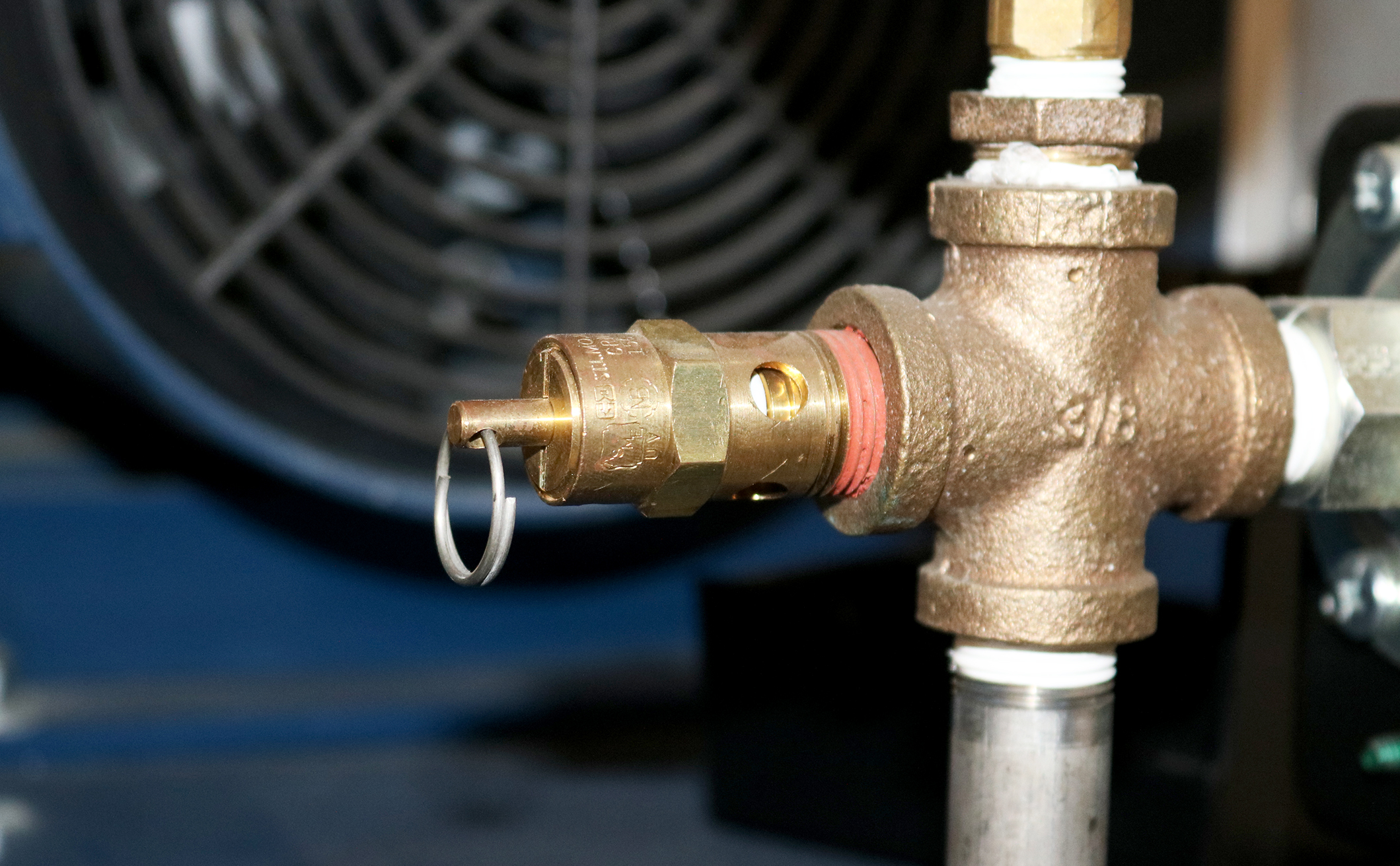
But that doesn’t mean you should never think about your compressor’s safety features. In most cases, they need to be inspected regularly to make sure they’re working properly. One key safety feature that should be inspected regularly is the air pressure relief valve (PRV), sometimes called a safety relief valve.
The pressure relief valve is a safety valve that protects the compressor component that it’s attached to from being exposed to a pressure above its rated maximum operating pressure. This rating, called the maximum working pressure (MWP), is the pressure that the vessel has been certified to continuously operate at safely.
So when a compressor is running at or below its maximum working pressure—in other words, when it’s running “normally”—the relief valve doesn’t do anything.
However, when the air pressure inside a compressor exceeds its MWP, the pressure relief valve will activate to “blow off” the excessive pressure within the compressor. Without a relief valve, the storage tank could rupture from the excessive pressure, damaging the compressor itself, possibly other property near it, and even causing injuries (or worse) to anyone standing nearby.
Before we can talk about how the air pressure relief valve works, we first need to look at how air pressure inside a compressor is managed when everything is running normally.
Under normal circumstances, the air pressure in a compressor is controlled by a pressure switch in an electro/mechanical control system or, in the case of an electronic controller, a pressure transducer and controller settings. When the cut-out set pressure for the pressure switch is reached, the compressor will stop compressing air (unload) until the cut-in set pressure is reached, at which time it will start compressing air again (load). If the pressure switch fails, the compressor would not be able to start compressing air again, or potentially worse, not be able to stop. Most compressors also have a high-pressure safety switch that should stop the compressor if the pressure exceeds the unload set point.
A pressure relief valve is a straightforward safety backup to the pressure switch and high-pressure switch, or the controller set points, should any of these components fail with the compressor running. The safety relief valve is set above the high-pressure safety switch and generally at or below the vessel’s maximum operating pressure. Inside the valve is a spring, and the pressure created by the spring’s tension keeps the valve closed under normal operating conditions. However, as the air pressure increases in pressure vessels (like the storage tank), it eventually exceeds the rated pressure of the relief valve, causing the relief valve to open and the excess pressure to be “blown off” to the atmosphere.
If the pressure relief valve fails open, air will continually vent to the atmosphere, preventing the air stream from becoming fully pressurized. The compressor should be shut down and the relief valve replaced before the compressor is restarted. The open relief valve will likely cause a loss of production and possible danger to personnel as a result of the flow of high-pressure air with flying debris and an unsafe sound level.
A pressure relief valve failing closed presents a potentially more dangerous situation. As noted earlier, the relief valve exists to allow excessive pressure to be “blown off” so that the air pressure inside the compressor’s pressure vessels don’t exceed their rated specifications. If the valve fails closed, this pressure venting can’t happen. Unless compressed air demand matches the compressed air supply, the pressure inside the compressor will continue to build. Eventually, the pressure increase would cause the storage tank to rupture, damaging the compressor and possibly causing additional damage and injury to property and people nearby.
If the relief valve is opening because the air pressure in the compressor has exceeded the valve’s pressure set point, that means the valve is working and doing what it was designed to do. But because this indicates the MWP of the compressor has been exceeded, the condition that’s causing excessive pressure should be diagnosed and corrected.
If the relief valve opening wasn’t caused by excessive pressure inside the compressor, then the valve is most likely “failing open”. Most likely, this is because the valve has become “soft” over time, i.e. the valve spring is providing less counterpressure, so it’s opening at a lower pressure than it should.
Whether the valve opened because of excessive pressure in the compressor or because the valve is failing, you should have your local air compressor distributor inspect your compressor before running it again for two reasons:
First, your distributor can determine whether the valve opened due to a failing relief valve or excessive compressors pressure and perform any needed maintenance or service to get your compressor running efficiently and safely again.
Second, regardless of why the pressure relief valve opened, replacing it may be recommended to ensure safe compressor operation, depending on the valve manufacturer. (Replacement is recommended for Sullair compressors.)
Important: Running the compressor after the relief valve has opened, regardless of the reason why it opened, can put both your property at risk of damage and people at risk of injury (or worse). While this may be obvious if the compressor is building up excess pressure, it also applies if the valve failed open. As noted above, even a valve that fails open poses some risk, and next time it could fail closed.
Given how critical a working air pressure relief valve is to the safe and efficient operation of your air compressor, you may wonder whether you need to do any regular inspecting or testing of the valve to make sure it is working. Because this can vary by manufacturer, you should consult your owner’s manual or contact your local air compressor distributor for frequency and type of inspection needed. For most Sullair compressors, inspection for damage or leakage is recommended, but testing is not recommended, as doing so may compromise the valve’s performance.
However, one thing you should do is schedule regular maintenance with your local air compressor distributor. As part of regular maintenance, a service technician can inspect the PRV and let you know it’s at an age or in a condition at which the manufacturer recommends replacement. Also, problems with the compressor’s performance, e.g. not reaching normal operating pressure, may help the service technician identify a failing relief valve after ruling out other possible causes.
When a pressure vessel like a receiver, sump tank or other storage vessel is purchased separately from the compressor, it may not be supplied with a pressure relief valve. To ensure its safe operation, you should add a PRV.
When selecting a PRV to add to the pressure vessel, you must choose a valve with a pressure set point set at or below the maximum working pressure of the vessel. You will find the MWP (and other useful information) on a tag welded to the pressure vessel. Also, flow capacity of the PRV must meet or exceed the total compressed air supplied to the vessel.
For example, if you have two compressors with capacities of 500 and 750 cfm (14.2 and 21.2 m³/min), and a pressure vessel with a maximum working pressure of 200 psi (13.8 bar), the minimum settings for a pressure relief valve would be 1250 cfm (35.4 m³/min) and a set point 200 psi (13.8 bar) or less.
Finally, when attaching the valve to the vessel, the porting must not be reduced to a size less than the size of the inlet port of the pressure relief valve.
Because the pressure relief valve is critical to the safe operation of your compressed air system, if you’re not sure how to select the correct PRV and properly and safely add it to the pressure vessel, contact your local air compressor distributor. They have the experience and expertise to ensure that the PRV is sized and installed correctly.
Safety valves and pressure relief valves are crucial for one main reason: safety. This means safety for the plant and equipment as well as safety for plant personnel and the surrounding environment.
Safety valves and pressure relief valves protect vessels, piping systems, and equipment from overpressure, which, if unchecked, can not only damage a system but potentially cause an explosion. Because these valves play such an important role, it’s absolutely essential that the right valve is used every time.
The valve size must correspond to the size of the inlet and discharge piping. The National Board specifies that the both the inlet piping and the discharge piping connected to the valve must be at least as large as the inlet/discharge opening on the valve itself.
The connection types are also important. For example, is the connection male or female? Flanged? All of these factors help determine which valve to use.
The set pressure of the valve must not exceed the maximum allowable working pressure (MAWP) of the boiler or other vessel. What this means is that the valve must open at or below the MAWP of the equipment. In turn, the MAWP of the equipment should be at least 10% greater than the highest expected operating pressure under normal circumstances.
Temperature affects the volume and viscosity of the gas or liquid flowing through the system. Temperature also helps determine the ideal material of construction for the valve. For example, steel valves can handle higher operating temperatures than valves made of either bronze or iron. Both the operating and the relieving temperature must be taken into account.
Back pressure, which may be constant or variable, is pressure on the outlet side of the pressure relief valve as a result of the pressure in the discharge system. It can affect the set pressure of the upstream valve and cause it to pop open repeatedly, which can damage the valve.
For installations with variable back pressure, valves should be selected so that the back pressure doesn’t exceed 10% of the valve set pressure. For installations with high levels of constant back pressure, a bellows-sealed valve or pilot-operated valve may be required.
Different types of service (steam, air, gas, etc.) require different valves. In addition, the valve material of construction needs to be appropriate for the service. For example, valves made of stainless steel are preferable for corrosive media.
Safety valves and relief valves must be able to relieve pressure at a certain capacity. The required capacity is determined by several factors including the geometry of the valve, the temperature of the media, and the relief discharge area.
These are just the basic factors that must be considered when selecting and sizing safety valves and relief valves. You must also consider the physical dimensions of the equipment and the plant, as well as other factors related to the environment in which the valve will operate.

Before youbuy compressed air receiver tank, take some time to learn about the device itself. Our guide to compressed air receiver tanks explains how they work, what they do, and how you can use them to maximize the efficiency of your compressed air system.
An air receiver tank (sometimes called an air compressor tank or compressed air storage tank) is what it sounds like: a tank that receives and stores compressed air after it exits theair compressor. This gives you a reserve of compressed air that you can draw on without running your air compressor.
An air receiver is a type ofpressure vessel; it holds compressed air under pressure for future use. The tanks come in a range of sizes and in both vertical and horizontal configurations.
An air receiver tank provides temporary storage for compressed air. It also helps your air compression system run more efficiently. The air receiver tank has three main functions in your compressed air system:
The primary role of an air receiver tank is to provide temporary storage for compressed air. Storing compressed air allows the system to average the peaks in compressed air demand over the course of a shift. You can think of your air receiver tank as a battery for your compressed air system, except it stores air instead of chemical energy. This air can be used to power short, high-demand events (up to 30 seconds) such as a quick burst of a sandblaster, dust collector pulse, or someone using a blowgun to dust themselves off. The air in the tank is available even when the compressor is not running. Storing compressed air reduces sudden demands on your air compressor, prolonging the life of your system. Using an air receiver tank may also allow you to use a smaller horsepower compressor for larger jobs.
The air receiver tank provides a steady stream of air to compressor controls, eliminating short-cycling and over-pressurization. Uneven compressed air utilization causes uneven demand on the air compressor, resulting in rapid cycling of the compressor controls as the compressor turns on and off to meet moment-by-moment demand. Each time the system turns on and off (or loads/unloads) is called a “cycle”; it is better for the compressor motor to keep these cycles as long as possible. Over time, frequent short cycling will lead to premature failure of switches and other compressor components. Rapid cycling can result in excessive wear of the motor contactor or even a direct motor short because of winding insulation. The air receiver tank eliminates short cycling and provides more consistent system pressure to controls.
As air is compressed under pressure, its temperature increases; this is a simple law of physics known as thePressure-Temperature Law. Depending on the type of air compressor you are using, the air discharged from the compressor may be as hot as 250 – 350°F. This is too hot for most air-operated equipment to use directly. Hotter air also contains more moisture, which will result in excess water vapor that will condense in control lines and tools if it is not removed. The condensed air must be cooled and dried before it is utilized. Aheat exchangeris used to remove excess heat caused by compression. The air receiver tank acts as a secondary heat exchanger; as air sits in the tank or slowly flows through it, it naturally cools over time. The air receiver tank supports the work of a primary heat exchanger; lowering the temperature of the air an additional 5 – 10°F is not uncommon.
As the air compressor cycles on and off, compressed air can be wasted. Every time arotary screw air compressorunloads, the sump tank (oil tank) is vented. Compressed air is released during the venting. Over time, this adds up to the loss of thousands of cubic feet of compressed air that could otherwise have been used to power processes in your facility. A properly sized air storage tank reduces frequent cycling and venting.
Compressed air storage also allows you to reduce the pressure at which your air compressor operates. Without a store of compressed air to draw on, the system will have to operate at higher pressures, so it is always ready to meet peak demands. In essence, you are asking your system to operate as if your facility is always running at maximum demand. This leads to increased energy use and wear and tear on the system. On average, for every 2 PSI that you increase the pressure of your system increases the energy demand by 1%. This can lead to hundreds or thousands of dollars added to your energy bills annually. As explained above, adding an air receiver tank to your compressed air system will even out these peaks in demand, allowing you to meet intermittent periods of high demand without increasing the overall pressure of your system.
The heat exchanger function of the air receiver tank helps to improve the efficiency of your air dryer. As air passes slowly through the receiver tank, it cools. Cooler air can’t hold as much moisture as warm air, so excess moisture condenses and falls out of the air as a liquid. The water drains out of a valve at the bottom of the tank. By removing some moisture in advance, the air receiver tank reduces the amount of work the air dryer needs to do. This improved efficiency translates to additional energy savings for your system.
When shopping for an air receiver tank, you may be asked whether you want “wet” or “dry” compressed air storage. The difference is in the location of the air storage tank in your compressed air system; there is no difference in tank construction or design.
“Wet” storage tanks are locatedbeforethe air drying system. Air flows through the tank in this configuration, entering through the bottom port from the compressor and exiting out the top to the dryer.
“Dry” storage tanks are locatedafterthe air dryers to store compressed air that has already been dried and filtered. It is not necessary to flow the compressed air through the tank for dry storage.
With wet air storage, the receiver tank is positioned in between the air compressor and the air dryer. Wet air enters the receiver tank from the air compressor through the lower port in the tank and exits through the upper port to enter the air drying system. A wet air receiver tank has several benefits.
As explained above, wet storage increases the efficiency of your air dryer by allowing excess water and lubricant to condense out of the air before it hits the dryer.
A wet air storage tank also prolongs the life of the pre-filter element, which is located in between the wet storage tank and the dryer. Since the air going through the filter is cleaner and dryer than it would be directly out of the air compressor, slugging of the filter with liquids is minimized, along with resulting pressure drop on the air dryer side of the system.
The compressor does not experience backpressure because the air does not go through filtration before entering the tank. This results in a steadier pressure signal to the compressor controller.
Without a dry air tank, air from the wet tank will have to go through the air dryer before it is used. During periods of high demand, the dryer is at risk of becoming over-capacitated as the system tries to pull air through at higher volumes than the dryer is rated for. If the dryer cannot keep up with the demand, drying efficiency is reduced, potentially leading to unwanted water in the air lines.
The ideal ratio of compressed air storage is1/3 wet to 2/3 dry capacity. For example, if you have a total of 1,200 gallons of compressed air storage, 800 gallons should be dry storage, and 400 gallons should be wet. Dry air is ready to use on-demand. The wet air tank increases the efficiency of the dryer and acts as a secondary reserve when dry air is exhausted. Dry air storage needs to be greater than wet storage to minimize the risk of over-capacitating the air dryer during periods of high demand.
An exception to this rule is for applications that have steady airflow without sharp peaks in demand. In this case, there is no need for a dry storage tank because air will simply flow through it without being stored up. This is often the case in robotic manufacturing facilities where airflow is consistent and predictable.
A good rule of thumb for most applications is to havethree to five gallons of air storage capacity per air compressor CFM output. So if your air compressor is rated for 100 CFM, you would want 300 to 500 gallons of compressed air storage. As explained above, 1/3 of the total storage capacity should be wet storage, and 2/3 should be dry storage.
While the standard rule works well for many applications, you will also want to consider other variables in determining your compressed air storage needs. Flow consistency has a large impact on storage requirements.
Facilities with very steady airflow, such as robotic facilities, typically don’t need as much stored air. That’s because they don’t have frequent high bursts of demand that rely on stored air. In this case, air storage can be reduced to 2 gallons per CFM of air compressor capacity. All storage should be wet storage in this case, as explained above.
Facilities with high variability in airflow and large peaks in demand may require larger volumes of stored air. This extra capacity will ensure that the system will be able to keep up with periods of high demand. Testing to determine CFM at peak demand will be needed to calculate air storage requirements.
The final consideration in determining compressed air storage requirements is the size of the pipework in the system. The pipes also store air for your compressed air system, and the larger the pipes, the more storage they provide. For systems with pipework of 2” or greater diameter, it may be worthwhile to consider that volume into the calculation.
Compressed air receiver tanks can be bulky, so many compressed air system owners would prefer to store them outside. Outdoor storage saves precious floor space in the facility.
It also helps to reduce strain on your HVAC system in warm weather. The compressed air storage tank radiates heat as hot air from the compressor cools within the tank, raising temperatures in the compressor room. Storing your tank outside avoids excess heat buildup in the compressor room and also helps the storage tank perform its secondary job as a heat exchanger more efficiently.
However, outdoor storage only works in milder, non-freezing climates. Make sure your climate is suitable for outdoor placement of your compressed air tank.
Outdoor storage of the air receiver tank is only appropriate for environments that stay above freezing year-round. In freezing temperatures, outdoor tanks can ice up and even rupture—a costly and potentially dangerous outcome. If your area experiences freezing temperatures during part of the year, it is safest to keep your tank indoors.
If you are storing your air receiver tank outdoors, be sure to conduct frequent inspections to monitor for corrosion. Any signs of corrosion should be addressed immediately to maintain the integrity of the tank.
The majority of air receiver tanks are bare steel on the inside with a primer coating on the outside to reduce corrosion. The exterior paint is commonly matched to the compressor equipment. A basic steel tank works well for most applications and is the least expensive option. However, they may be prone to corrosion if too much liquid is allowed to build up inside the tank.
Epoxy coatings are sprayed onto the interior as a liquid and then cured into a tough, anti-corrosive coating. Epoxies work by creating a moisture-proof barrier between the air and the base metal of the tank.
Both methods provide long-lasting protection for the interior of the tank, but they do add to the cost and lead time. Coated or galvanized tanks are better at maintaining air purity because they reduce the risk of particulates caused by corrosion entering the airstream. Applications needing higher purity air, or users concerned about the longevity of their air tanks, may want to consider one of these options.
Stainless steel air receiver tanks are primarily used for specialty applications where very high-purity air is required. They are the most expensive option, but they are highly durable and corrosion-resistant and maintain exceptional air purity. Hospitals, labs, electronics manufacturers, and other applications requiring high-purity air should consider a stainless steel tank.
Air receiver tank accessories are essential for tank safety and operation. While the tank itself is just a large sealed metal tube, all tanks must have at a minimum:
Automatic drain valves eliminate the need for daily manual draining of liquid inside the air receiver tank. Anelectric automatic drain valveis programmed to open at set intervals to let accumulated liquid drain out.
Zero air-loss condensate drainsalso provide automatic drainage of the tank. Instead of draining at set intervals, they use a float mechanism to control drainage. The drain will only open when needed, saving energy and reducing air loss from the tank.
The pressure gauge provides a visual indicator for the interior pressure of the air in the tank. You need the gauge to monitor pressures and ensure that the tank is not under stress from over-pressurization.
A pressure relief valve is required for all air receiver tanks per OSHA and ASME guidelines. The pressure relief valve opens automatically to release some air if pressures in the tank are too high. This safety mechanism is essential to minimize the risk of a dangerous rupture due to over-pressurization. The relief valve is typically set to 10% higher than the working pressure of the compressed air system but never more than the rated pressure of the tank’s ASME certification.
Vibration pads are not required for all applications, but they are recommended if the air compressor is mounted on top of the tank. Vibration pads absorb vibrations from the compressor motor and reduce fatigue on the tank.
Many buyers wonder if ASME certification is important for air receiver tanks—and the answer is yes. All air receiver tanks used in industrial applications must be certified by ASME for safety and performance.
The American Society of Mechanical Engineers, or ASME, is an organization that sets engineering codes and manufacturing standards for a variety of machines, parts, and system components. ASME acts as an independent quality assurance organization to ensure the safety and quality of manufactured items. An ASME certification stamp means that the manufacturer has met all safety and engineering standards for their product.
ASME has developed a set of codes and standards for pressure vessels, including air receiver tanks. The ASMEBoiler and Pressure Vessel Certification Programsets rules governing the design, fabrication, assembly, and inspection of pressure vessel components during construction. These rules include engineering standards for the thickness of the tank body, welds and joints, connections, and other components of the tank. Tank manufacturers must conform to all of the rules to obtain ASME certification.
Some big box stores carry non-code air receiver tanks. While these may be cheaper, they have not undergone the rigorous manufacturing processes and quality testing needed to ensure that they are safe and reliable. Using a non-code air receiver tank could put your life and the lives of your coworkers at risk.
If you are not sure whether or not your air receiver tank meets code requirements, you should have it inspected. Your local Fire Marshall may provide this service. They will stop in and test your tank with ultrasonic metalthickness testing technology. If your air receiver tank does not pass the inspection, it should be decommissioned and replaced immediately.
All air receiver tanks must also be inspected periodically once they are installed. OSHA does not mandate a specific testing interval, but it is recommended that all air receiver tanks be inspected at least annually. Your insurance company or local governing board may have different requirements. OSHA requires that formal inspections be performed by an inspector holding a validNational Board Commissionand in accordance with the applicable chapters of the National Board Inspection Code. Manufacturers are required to keep records of formal inspections and make them available to OSHA representatives upon request.
In between formal board inspections, manufacturers should conduct frequent visual inspections of the air receiver tank to look for signs of corrosion, damage or weld failure. Check drains daily and pressure relief valves quarterly to make sure they are operating correctly. Contact your manufacturer or compressed air system installer immediately if you see any signs of problems with your air receiver tank.
Pressure vessels must be built to withstand high internal pressures over a long period of time. Over time, corrosion, stress, and fatigue can make tank failure more likely. The most common causes of air receiver failure are:
The high internal pressures within an air receiver tank make failure extremely hazardous. Cracking or weld failure can cause the tank to burst with explosive force, projecting large pieces of metal or fragments of shrapnel at high speed. Air receiver tank failure may result in extensive damage to the facility and nearby equipment and severe injury or death for nearby workers.
An appropriately-sized air receiver tank will improve the efficiency of your system—and can even reduce your operating costs for your compressed air system. Your air receiver tank reduces energy consumption and saves wear and tear on your system.
Your compressed air receiver tank is like a battery for your facility, providing an extra reservoir of compressed air you can draw on during periods of high demand. This lets you reduce the overall operating pressures for your system, resulting in lower energy costs. You may also be able to purchase a smaller air compressor with lower CFM capacity by relying on your air receiver tank for high-demand events.
As explained above, the air receiver tank reduces cycles counts for your air compressor by evening out peaks in compressed air demands. Lower cycle counts add up to lower energy use and less wear and tear on other system components, extending the life of your air compressor.
The air receiver tank functions as a pulsation dampening device, absorbing vibrations from the air compressor motor and pulsations in the air stream. This reduces fatigue on piping and other system components.
As the air cools in the air receiver tank, the excess liquid condenses and falls out of the air. This results in less work for the air dryer and less energy consumption.
Particulates can enter the airstream due to corrosion within the system, motor exhaust from the air compressor, or particulates in facility air. Many of these particulates will fall out of the air along with condensate within the air receiver tank. The excess dirt is then simply drained away with the liquids. As a result, the air entering the air dryer is both cleaner and drier than air directly from the air compressor.
Your air receiver tank is an essential component of your compressed air system. Having a properly sized air receiver tank ensures the safe and efficient operation of your system and provides a reservoir of extra power for use during periods of peak demand.
If you’re not sure how much air storage capacity you need, or if you have questions about maintaining your tank for safe operation, the experts at Fluid-Aire Dynamics can help. We will perform an assessment of your compressed air usage patterns and recommend an air receiver tank that will fit your needs. We can also help you inspect, repair, or upgrade your current storage system.

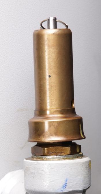
These high pressure safety valves combine extra sturdy construction, a patented* three-piece disc including seat seal of Teflon, and finely adjustable blow down control-resulting in long service life with superior seat tightness at operating pressure
Multi-stage compressor intercoolers and after coolers, Receivers Especially recommended for thermal expansion relief and/or full rated capacity discharge. When equipped with S/S springs, or all stainless steel assemblies, for low temperature-cryogenic- installations.

Air conditioning heat pump pressure bypass valves are important in any air conditioning system. These valves help regulate the amount of refrigerant sent through an AC system and help keep it running smoothly and efficiently. Without these valves, the system would be unable to operate properly, causing a wide range of problems from decreased efficiency to total system failure. Here we will provide a brief overview of how AC heat pump pressure bypass valves work, their advantages, and why they are so important for your AC system.
The most common type of pressure bypass valve is a fixed-orifice design. This type consists of two ports – one port allows the refrigerant to pass through while the other directs high-pressure liquid away from the compressor.
A pressure bypass valve is an important component of an air conditioning heat pump system. It helps to prevent excessive high-pressure buildup, thus ensuring that your system operates efficiently and safely. Pressure bypass valves are most commonly found in split systems, as they control the refrigerant flow.
The main purpose of a pressure bypass valve is to protect the air conditioning compressor from being damaged due to excessive pressure build-up. Allowing excess liquid refrigerant to bypass the compressor helps reduce the risk of damage caused by overpressurization. It also prevents the liquid refrigerant from entering other components within the system and causing further damage. The valve is typically installed at either end of a heat pump’s evaporator coil, with both ends connected via pipes or hoses.
A pressure bypass valve is a critical component of an air conditioning heat pump system. It is designed to control refrigerant flow in the system, allowing it to be safely regulated and maintained. The valve helps to maintain a safe level of pressure within the system and prevents damage from occurring due to excessively high-pressure levels.
The operation of a pressure bypass valve is relatively simple. When the system’s temperature increases, causing the refrigerant pressure to rise, it triggers the valve to open and allows some of that pressure to escape. This reduces the overall pressure to maintain a safe operating level, allowing optimal performance and efficiency. When temperatures drop again, and lower pressures are reached, the valve will close back up automatically until needed.
As homeowners look for ways to lower their energy bills and maintain their air conditioning systems, they should consider the advantages of an air conditioning heat pump pressure bypass valve. This device helps keep the system running smoothly and can reduce costly repairs due to its ability to regulate high-pressure conditions.
The pressure bypass valve is designed to open when system pressures become too high. This prevents damage by allowing refrigerant gas or liquid to flow into another location in a controlled manner. As the refrigerant flows through the valve, it equalizes temperatures between indoor and outdoor units, increasing efficiency while lowering operating costs.
Pressure bypass valves are essential to the air conditioning and heat pump system. They help regulate the pressure within the system, ensuring it works correctly and safely. However, like all mechanical components, pressure bypass valves can experience common issues that may require attention from a qualified HVAC technician.
The most common problem with pressure bypass valves is clogging or sticking due to debris buildup in the valve itself. This can cause airflow restriction, reducing efficiency and increasing energy costs for homeowners. In addition, if dirt or other contaminants enter the valve housing, it can cause an imbalance in pressure levels leading to potential leaks within the system. Other less frequent issues include malfunctioning solenoids or damaged O-rings, which will require replacement parts for repair.
Are you looking for an easy way to install a pressure bypass valve? Installing an air conditioning heat pump pressure bypass valve can be tricky, but understanding the process and having the right tools can make it easier. Keep reading to learn more about installation tips for pressure bypass valves that will help make your project successful.
When installing a pressure bypass valve, it is important to ensure you have all the necessary components before beginning. This includes any mounting hardware, such as screws or brackets, tubing and clamps, and the correct size O-rings. Additionally, you’ll need a wrench set, screwdriver set, wire cutters, adjustable pipe wrench, and tubing bender. Once you’ve gathered all of these items together, check your manufacturer’s instructions for specific installation and setup procedures details.
The air conditioning heat pump pressure bypass valve is an important part of any air conditioning system. As such, it is important to understand the benefits and considerations of having one installed in a residential or commercial space.
One of the major advantages of having a pressure bypass valve installed is that it helps keep the system running efficiently. By preventing over-pressurization, the valve ensures proper operation and prevents costly repairs or downtime due to malfunction. Additionally, it helps protect against water damage should there be a sudden change in pressure levels in the system, which can help reduce overall maintenance costs.
However, like any other system component, some considerations are associated with installing a pressure bypass valve. These include ensuring proper installation by qualified personnel to ensure safe operation and regularly inspecting and maintaining the device for optimal performance.


 8613371530291