
air receiver tank safety valve free sample
Before youbuy compressed air receiver tank, take some time to learn about the device itself. Our guide to compressed air receiver tanks explains how they work, what they do, and how you can use them to maximize the efficiency of your compressed air system.
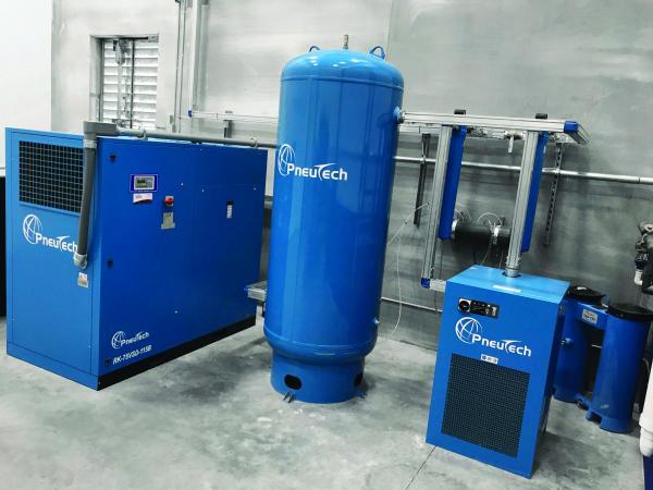
An air receiver tank (sometimes called an air compressor tank or compressed air storage tank) is what it sounds like: a tank that receives and stores compressed air after it exits theair compressor. This gives you a reserve of compressed air that you can draw on without running your air compressor.
An air receiver is a type ofpressure vessel; it holds compressed air under pressure for future use. The tanks come in a range of sizes and in both vertical and horizontal configurations.
An air receiver tank provides temporary storage for compressed air. It also helps your air compression system run more efficiently. The air receiver tank has three main functions in your compressed air system:
The primary role of an air receiver tank is to provide temporary storage for compressed air. Storing compressed air allows the system to average the peaks in compressed air demand over the course of a shift. You can think of your air receiver tank as a battery for your compressed air system, except it stores air instead of chemical energy. This air can be used to power short, high-demand events (up to 30 seconds) such as a quick burst of a sandblaster, dust collector pulse, or someone using a blowgun to dust themselves off. The air in the tank is available even when the compressor is not running. Storing compressed air reduces sudden demands on your air compressor, prolonging the life of your system. Using an air receiver tank may also allow you to use a smaller horsepower compressor for larger jobs.
The air receiver tank provides a steady stream of air to compressor controls, eliminating short-cycling and over-pressurization. Uneven compressed air utilization causes uneven demand on the air compressor, resulting in rapid cycling of the compressor controls as the compressor turns on and off to meet moment-by-moment demand. Each time the system turns on and off (or loads/unloads) is called a “cycle”; it is better for the compressor motor to keep these cycles as long as possible. Over time, frequent short cycling will lead to premature failure of switches and other compressor components. Rapid cycling can result in excessive wear of the motor contactor or even a direct motor short because of winding insulation. The air receiver tank eliminates short cycling and provides more consistent system pressure to controls.
As air is compressed under pressure, its temperature increases; this is a simple law of physics known as thePressure-Temperature Law. Depending on the type of air compressor you are using, the air discharged from the compressor may be as hot as 250 – 350°F. This is too hot for most air-operated equipment to use directly. Hotter air also contains more moisture, which will result in excess water vapor that will condense in control lines and tools if it is not removed. The condensed air must be cooled and dried before it is utilized. Aheat exchangeris used to remove excess heat caused by compression. The air receiver tank acts as a secondary heat exchanger; as air sits in the tank or slowly flows through it, it naturally cools over time. The air receiver tank supports the work of a primary heat exchanger; lowering the temperature of the air an additional 5 – 10°F is not uncommon.
As the air compressor cycles on and off, compressed air can be wasted. Every time arotary screw air compressorunloads, the sump tank (oil tank) is vented. Compressed air is released during the venting. Over time, this adds up to the loss of thousands of cubic feet of compressed air that could otherwise have been used to power processes in your facility. A properly sized air storage tank reduces frequent cycling and venting.
Compressed air storage also allows you to reduce the pressure at which your air compressor operates. Without a store of compressed air to draw on, the system will have to operate at higher pressures, so it is always ready to meet peak demands. In essence, you are asking your system to operate as if your facility is always running at maximum demand. This leads to increased energy use and wear and tear on the system. On average, for every 2 PSI that you increase the pressure of your system increases the energy demand by 1%. This can lead to hundreds or thousands of dollars added to your energy bills annually. As explained above, adding an air receiver tank to your compressed air system will even out these peaks in demand, allowing you to meet intermittent periods of high demand without increasing the overall pressure of your system.
The heat exchanger function of the air receiver tank helps to improve the efficiency of your air dryer. As air passes slowly through the receiver tank, it cools. Cooler air can’t hold as much moisture as warm air, so excess moisture condenses and falls out of the air as a liquid. The water drains out of a valve at the bottom of the tank. By removing some moisture in advance, the air receiver tank reduces the amount of work the air dryer needs to do. This improved efficiency translates to additional energy savings for your system.
When shopping for an air receiver tank, you may be asked whether you want “wet” or “dry” compressed air storage. The difference is in the location of the air storage tank in your compressed air system; there is no difference in tank construction or design.
“Wet” storage tanks are locatedbeforethe air drying system. Air flows through the tank in this configuration, entering through the bottom port from the compressor and exiting out the top to the dryer.
“Dry” storage tanks are locatedafterthe air dryers to store compressed air that has already been dried and filtered. It is not necessary to flow the compressed air through the tank for dry storage.
With wet air storage, the receiver tank is positioned in between the air compressor and the air dryer. Wet air enters the receiver tank from the air compressor through the lower port in the tank and exits through the upper port to enter the air drying system. A wet air receiver tank has several benefits.
As explained above, wet storage increases the efficiency of your air dryer by allowing excess water and lubricant to condense out of the air before it hits the dryer.
A wet air storage tank also prolongs the life of the pre-filter element, which is located in between the wet storage tank and the dryer. Since the air going through the filter is cleaner and dryer than it would be directly out of the air compressor, slugging of the filter with liquids is minimized, along with resulting pressure drop on the air dryer side of the system.
The compressor does not experience backpressure because the air does not go through filtration before entering the tank. This results in a steadier pressure signal to the compressor controller.
Without a dry air tank, air from the wet tank will have to go through the air dryer before it is used. During periods of high demand, the dryer is at risk of becoming over-capacitated as the system tries to pull air through at higher volumes than the dryer is rated for. If the dryer cannot keep up with the demand, drying efficiency is reduced, potentially leading to unwanted water in the air lines.
The ideal ratio of compressed air storage is1/3 wet to 2/3 dry capacity. For example, if you have a total of 1,200 gallons of compressed air storage, 800 gallons should be dry storage, and 400 gallons should be wet. Dry air is ready to use on-demand. The wet air tank increases the efficiency of the dryer and acts as a secondary reserve when dry air is exhausted. Dry air storage needs to be greater than wet storage to minimize the risk of over-capacitating the air dryer during periods of high demand.
An exception to this rule is for applications that have steady airflow without sharp peaks in demand. In this case, there is no need for a dry storage tank because air will simply flow through it without being stored up. This is often the case in robotic manufacturing facilities where airflow is consistent and predictable.
A good rule of thumb for most applications is to havethree to five gallons of air storage capacity per air compressor CFM output. So if your air compressor is rated for 100 CFM, you would want 300 to 500 gallons of compressed air storage. As explained above, 1/3 of the total storage capacity should be wet storage, and 2/3 should be dry storage.
While the standard rule works well for many applications, you will also want to consider other variables in determining your compressed air storage needs. Flow consistency has a large impact on storage requirements.
Facilities with very steady airflow, such as robotic facilities, typically don’t need as much stored air. That’s because they don’t have frequent high bursts of demand that rely on stored air. In this case, air storage can be reduced to 2 gallons per CFM of air compressor capacity. All storage should be wet storage in this case, as explained above.
Facilities with high variability in airflow and large peaks in demand may require larger volumes of stored air. This extra capacity will ensure that the system will be able to keep up with periods of high demand. Testing to determine CFM at peak demand will be needed to calculate air storage requirements.
The final consideration in determining compressed air storage requirements is the size of the pipework in the system. The pipes also store air for your compressed air system, and the larger the pipes, the more storage they provide. For systems with pipework of 2” or greater diameter, it may be worthwhile to consider that volume into the calculation.
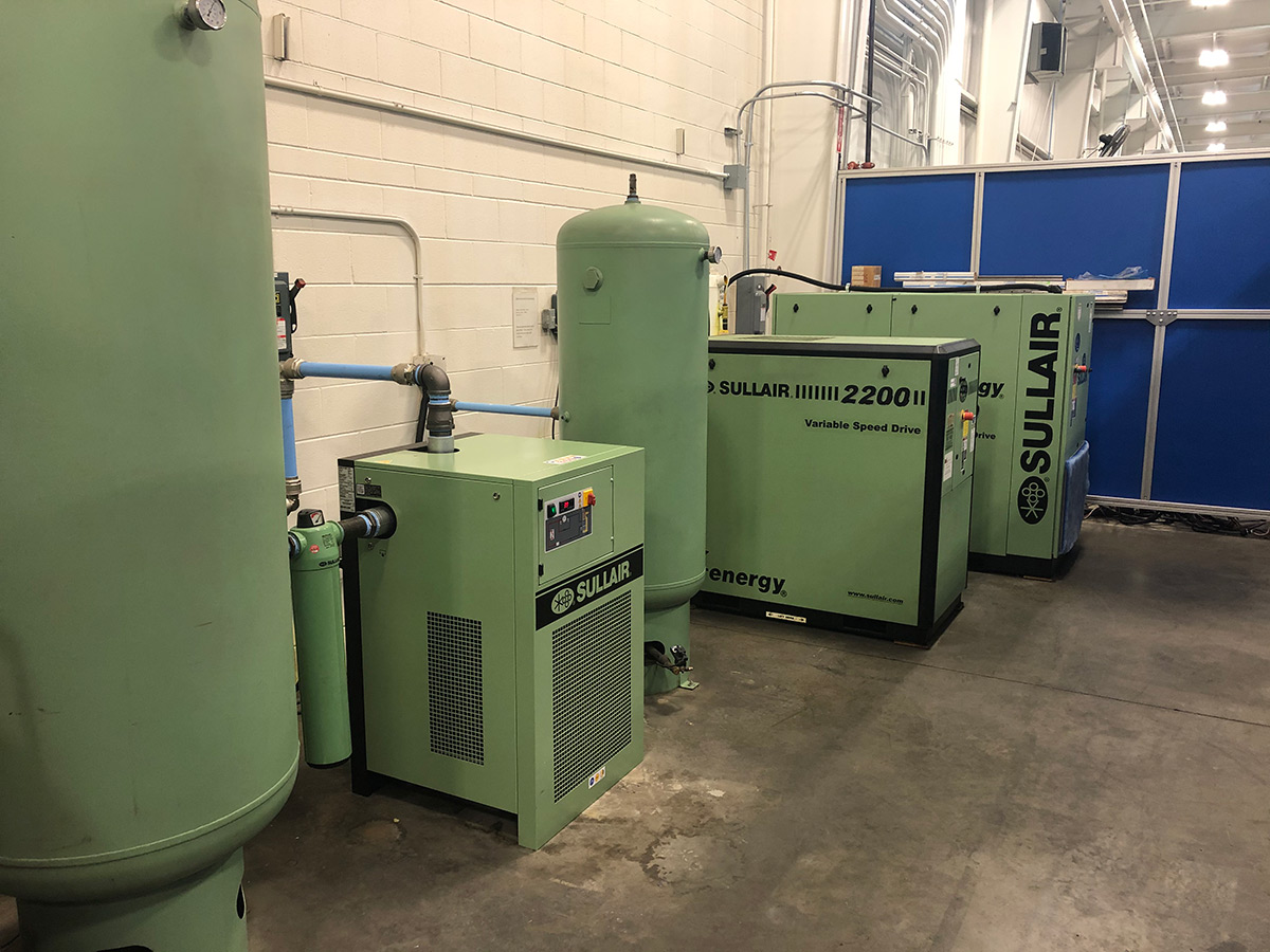
Compressed air receiver tanks can be bulky, so many compressed air system owners would prefer to store them outside. Outdoor storage saves precious floor space in the facility.
It also helps to reduce strain on your HVAC system in warm weather. The compressed air storage tank radiates heat as hot air from the compressor cools within the tank, raising temperatures in the compressor room. Storing your tank outside avoids excess heat buildup in the compressor room and also helps the storage tank perform its secondary job as a heat exchanger more efficiently.
However, outdoor storage only works in milder, non-freezing climates. Make sure your climate is suitable for outdoor placement of your compressed air tank.
Outdoor storage of the air receiver tank is only appropriate for environments that stay above freezing year-round. In freezing temperatures, outdoor tanks can ice up and even rupture—a costly and potentially dangerous outcome. If your area experiences freezing temperatures during part of the year, it is safest to keep your tank indoors.
If you are storing your air receiver tank outdoors, be sure to conduct frequent inspections to monitor for corrosion. Any signs of corrosion should be addressed immediately to maintain the integrity of the tank.
If your area is subject to cooler temperatures with occasional risk of icing, take special care of your tank in cooler weather. The tank will generate some heat on its own. However, if temperatures drop too far, the tank is still at risk of freezing. Insulating your tank and providing auxiliary heating during cold weather may be necessary to prevent damage.
The majority of air receiver tanks are bare steel on the inside with a primer coating on the outside to reduce corrosion. The exterior paint is commonly matched to the compressor equipment. A basic steel tank works well for most applications and is the least expensive option. However, they may be prone to corrosion if too much liquid is allowed to build up inside the tank.
Epoxy coatings are sprayed onto the interior as a liquid and then cured into a tough, anti-corrosive coating. Epoxies work by creating a moisture-proof barrier between the air and the base metal of the tank.
Galvanized tanks are treated with a protective zinc coating that halts the formation of rust. Zinc protects the base metal by reacting chemically with corrosive agents before they can reach the base.
Both methods provide long-lasting protection for the interior of the tank, but they do add to the cost and lead time. Coated or galvanized tanks are better at maintaining air purity because they reduce the risk of particulates caused by corrosion entering the airstream. Applications needing higher purity air, or users concerned about the longevity of their air tanks, may want to consider one of these options.
Stainless steel air receiver tanks are primarily used for specialty applications where very high-purity air is required. They are the most expensive option, but they are highly durable and corrosion-resistant and maintain exceptional air purity. Hospitals, labs, electronics manufacturers, and other applications requiring high-purity air should consider a stainless steel tank.
Air receiver tank accessories are essential for tank safety and operation. While the tank itself is just a large sealed metal tube, all tanks must have at a minimum:
Automatic drain valves eliminate the need for daily manual draining of liquid inside the air receiver tank. Anelectric automatic drain valveis programmed to open at set intervals to let accumulated liquid drain out.
Zero air-loss condensate drainsalso provide automatic drainage of the tank. Instead of draining at set intervals, they use a float mechanism to control drainage. The drain will only open when needed, saving energy and reducing air loss from the tank.
The pressure gauge provides a visual indicator for the interior pressure of the air in the tank. You need the gauge to monitor pressures and ensure that the tank is not under stress from over-pressurization.
A pressure relief valve is required for all air receiver tanks per OSHA and ASME guidelines. The pressure relief valve opens automatically to release some air if pressures in the tank are too high. This safety mechanism is essential to minimize the risk of a dangerous rupture due to over-pressurization. The relief valve is typically set to 10% higher than the working pressure of the compressed air system but never more than the rated pressure of the tank’s ASME certification.
Vibration pads are not required for all applications, but they are recommended if the air compressor is mounted on top of the tank. Vibration pads absorb vibrations from the compressor motor and reduce fatigue on the tank.
Many buyers wonder if ASME certification is important for air receiver tanks—and the answer is yes. All air receiver tanks used in industrial applications must be certified by ASME for safety and performance.
The American Society of Mechanical Engineers, or ASME, is an organization that sets engineering codes and manufacturing standards for a variety of machines, parts, and system components. ASME acts as an independent quality assurance organization to ensure the safety and quality of manufactured items. An ASME certification stamp means that the manufacturer has met all safety and engineering standards for their product.
ASME has developed a set of codes and standards for pressure vessels, including air receiver tanks. The ASMEBoiler and Pressure Vessel Certification Programsets rules governing the design, fabrication, assembly, and inspection of pressure vessel components during construction. These rules include engineering standards for the thickness of the tank body, welds and joints, connections, and other components of the tank. Tank manufacturers must conform to all of the rules to obtain ASME certification.
Some big box stores carry non-code air receiver tanks. While these may be cheaper, they have not undergone the rigorous manufacturing processes and quality testing needed to ensure that they are safe and reliable. Using a non-code air receiver tank could put your life and the lives of your coworkers at risk.
If you are not sure whether or not your air receiver tank meets code requirements, you should have it inspected. Your local Fire Marshall may provide this service. They will stop in and test your tank with ultrasonic metalthickness testing technology. If your air receiver tank does not pass the inspection, it should be decommissioned and replaced immediately.
All air receiver tanks must also be inspected periodically once they are installed. OSHA does not mandate a specific testing interval, but it is recommended that all air receiver tanks be inspected at least annually. Your insurance company or local governing board may have different requirements. OSHA requires that formal inspections be performed by an inspector holding a validNational Board Commissionand in accordance with the applicable chapters of the National Board Inspection Code. Manufacturers are required to keep records of formal inspections and make them available to OSHA representatives upon request.
In between formal board inspections, manufacturers should conduct frequent visual inspections of the air receiver tank to look for signs of corrosion, damage or weld failure. Check drains daily and pressure relief valves quarterly to make sure they are operating correctly. Contact your manufacturer or compressed air system installer immediately if you see any signs of problems with your air receiver tank.
Pressure vessels must be built to withstand high internal pressures over a long period of time. Over time, corrosion, stress, and fatigue can make tank failure more likely. The most common causes of air receiver failure are:
The high internal pressures within an air receiver tank make failure extremely hazardous. Cracking or weld failure can cause the tank to burst with explosive force, projecting large pieces of metal or fragments of shrapnel at high speed. Air receiver tank failure may result in extensive damage to the facility and nearby equipment and severe injury or death for nearby workers.
An appropriately-sized air receiver tank will improve the efficiency of your system—and can even reduce your operating costs for your compressed air system. Your air receiver tank reduces energy consumption and saves wear and tear on your system.
Your compressed air receiver tank is like a battery for your facility, providing an extra reservoir of compressed air you can draw on during periods of high demand. This lets you reduce the overall operating pressures for your system, resulting in lower energy costs. You may also be able to purchase a smaller air compressor with lower CFM capacity by relying on your air receiver tank for high-demand events.
As explained above, the air receiver tank reduces cycles counts for your air compressor by evening out peaks in compressed air demands. Lower cycle counts add up to lower energy use and less wear and tear on other system components, extending the life of your air compressor.
The air receiver tank functions as a pulsation dampening device, absorbing vibrations from the air compressor motor and pulsations in the air stream. This reduces fatigue on piping and other system components.
As the air cools in the air receiver tank, the excess liquid condenses and falls out of the air. This results in less work for the air dryer and less energy consumption.
Particulates can enter the airstream due to corrosion within the system, motor exhaust from the air compressor, or particulates in facility air. Many of these particulates will fall out of the air along with condensate within the air receiver tank. The excess dirt is then simply drained away with the liquids. As a result, the air entering the air dryer is both cleaner and drier than air directly from the air compressor.
Your air receiver tank is an essential component of your compressed air system. Having a properly sized air receiver tank ensures the safe and efficient operation of your system and provides a reservoir of extra power for use during periods of peak demand.
If you’re not sure how much air storage capacity you need, or if you have questions about maintaining your tank for safe operation, the experts at Fluid-Aire Dynamics can help. We will perform an assessment of your compressed air usage patterns and recommend an air receiver tank that will fit your needs. We can also help you inspect, repair, or upgrade your current storage system.

Your air receiver tank works hard to keep your compressed air system running at optimal efficiency. For best results and safe operation, it’s important to make sure you have adequate storage capacity for your application. You also need to take proper care of your tank once it is installed. In this article we provide advice for air receiver tank sizing, safety and storage.
A good rule of thumb for most applications is to havethree to five gallons of air storage capacity per air compressor cfm output. So if your air compressor is rated for 100 cfm, you would want 300 to 500 gallons of compressed air storage. As we’ll explain in more detail below, 1/3 of the total storage capacity should be wet storage and 2/3 should be dry storage.
While the standard rule works well for many applications, you will also want to consider other variables in determining your compressed air storage needs. Flow consistency has a large impact on storage requirements.
Facilities with very steady airflow, such as robotic facilities, typically don’t need as much stored air. That’s because they don’t have frequent high bursts of demand that rely on stored air. In this case, air storage can be reduced to two gallons per cfm of air compressor capacity. All storage should be wet storage in this case.
Facilities with high variability in airflow and large peaks in demand may require larger volumes of stored air. This extra capacity will ensure that the system will be able to keep up with periods of high demand. Testing to determine cfm at peak demand will be needed to calculate air storage requirements.
The final consideration in determining compressed air storage requirements is the size of the pipework in the system. The pipes also store air for your compressed air system, and the larger the pipes, the more storage they provide. For systems with pipework of two inches or greater diameter, it may be worthwhile to consider that volume in the calculation.
When shopping for an air receiver tank, you may be asked whether you want “wet” or “dry” compressed air storage. The difference is in the location of the air storage tank in your compressed air system; there is no difference in tank construction or design.
“Wet” storage tanks are located before the air drying system. Air flows through the tank in this configuration, entering through the bottom port from the air compressor and exiting out the top to the dryer.
“Dry” storage tanks are located after the air dryers to store compressed air that has already been dried and filtered. It is not necessary to flow the compressed air through the tank for dry storage.
Wet storage increases the efficiency of your air dryer and prolongs the life of the pre-filter element by allowing excess water and lubricant to condense out of the system before it hits the filter and dryer. This also reduces pressure drop on the air dryer side of the system and provides a steadier pressure signal to the compressor controller.
Dry compressed air is ready to use right out of the tank. This reduces the risk that the air dryer will become over-capacitated during high-demand events.
The ideal ratio of compressed air storage for most applications is 1/3 wet to 2/3 dry capacity. For example, if you have a total of 1,200 gallons of compressed air storage, 800 gallons should be dry storage and 400 gallons should be wet. Dry air is ready to use on demand. The wet air tank increases the efficiency of the dryer and acts as a secondary reserve when dry air is exhausted. Dry air storage needs to be greater than wet storage to minimize the risk of over-capacitating the air dryer during periods of high demand.
An exception to this rule is for applications that have steady airflow without sharp peaks in demand. In this case, there is no need for a dry storage tank because air will simply flow through it without being stored up. This is often the case in robotic manufacturing facilities where airflow is consistent and predictable.
The American Society of Mechanical Engineers (ASME) has developed a set of codes and standards for pressure vessels, including air receiver tanks. The ASME Boiler and Pressure Vessel Certification Program sets rules governing the design, fabrication, assembly and inspection of pressure vessel components during construction. These rules include engineering standards for the thickness of the tank body, welds and joints, connections and other components of the tank. Tank manufacturers must conform to all of the rules to obtain ASME certification.
All air receiver tanks used in industrial applications must be certified by ASME for safety and performance. Non-code air receiver tanks should never be used, especially for industrial applications.
Some big box stores carry non-code air receiver tanks. While these may be cheaper, they have not undergone the rigorous manufacturing processes and quality testing needed to ensure that they are safe and reliable. Using a non-code air receiver tank could put your life and the lives of your coworkers at risk.
Pressure vessels must be built to withstand high internal pressures over a long period of time. Over time, corrosion, stress and fatigue can make tank failure more likely. The most common causes of air receiver failure are:
The high internal pressures within an air receiver tank make failure extremely hazardous. Cracking or weld failure can cause the tank to burst with explosive force, projecting large pieces of metal or fragments of shrapnel at high speed. Air receiver tank failure may result in extensive damage to the facility and nearby equipment and severe injury or death for nearby workers.
A well-maintained air receiver tank can last for many years. To get the most out of your investment, it is important to follow all operating guidelines, perform regular maintenance and inspection, and protect the tank from climate extremes.
Follow all operating guidelines, perform regular maintenance and inspection, and protect the tank from climate extremes to get the most out of your air receiver tank.
For safe operation, it is essential to follow all safety guidelines listed in the owner’s manual for your air receiver tank. To improve tank safety, be sure to:
Periodically inspect the tank for corrosion, signs of weld seam stress, cracks, thinning of the vessel walls, and other defects. Any signs of corrosion should be addressed immediately to maintain the integrity of the tank.
If you are not sure whether or not your air receiver tank meets code requirements, you should have it inspected. Your local fire marshall may provide this service. They will stop in and test your tank with ultrasonic metal thickness testing technology. If your air receiver tank does not pass the inspection, it should be decommissioned and replaced immediately.
All air receiver tanks must also be inspected periodically once they are installed. OSHA does not mandate a specific testing interval, but it is recommended that all air receiver tanks be inspected at least annually. Your insurance company or local governing board may have different requirements. OSHA requires that formal inspections be performed by an inspector holding a valid National Board Commission and in accordance with the applicable chapters of the National Board Inspection Code. Manufacturers are required to keep records of formal inspections and make them available to OSHA representatives upon request.
The inspector will review the current operating certificate and perform an overall assessment of the air receiver, piping and other systems. This will include visually inspecting the vessel walls and all support and mounting bracket attachment welds for evidence of corrosion, cracking, denting, gauges, punctures or weld failures. Internal inspection of the vessel walls may be conducted using cameras or sensors. Where visual internal inspection is impractical, inspectors may instead perform thickness readings using an ultrasonic sensor to look for signs of vessel wall thinning. In addition, the inspector will check:
In between formal board inspections, companies should conduct frequent visual inspections of the air receiver tank to look for signs of corrosion, damage or weld failure. Check drains daily and pressure relief valves quarterly to make sure they are operating correctly. Contact your compressed air system manufacturer or installer immediately if you see any signs of problems with your air receiver tank.
With a focus on Demand-Side Optimization, compressed air dryers, filters, condensate management, tanks, piping and pneumatic technologies are profiled. How to ensure system reliability, while reducing pressure drop and demand, is explored through System Assessment case studies.
Compressed air receiver tanks can be bulky, so many compressed air system owners would prefer to store them outside. Outdoor storage saves precious floorspace in the facility. It also helps to reduce strain on your HVAC system in warm weather. The compressed air storage tank radiates heat as hot air from the air compressor cools within the tank. Storing your tank outside avoids excess heat buildup in the air compressor room and also helps the storage tank perform its secondary job as a heat exchanger more efficiently.
The decision to store air receiver tanks inside, or outside of a facility are driven by multiple factors, including space considerations and the local climate.
On the other hand, outdoor storage leaves the air receiver tank vulnerable to temperature extremes and moisture damage. Make sure your climate is suitable for outdoor placement of your compressed air tank. Outdoor storage of the air receiver tank is only appropriate for environments that stay above freezing year-round. In freezing temperatures, outdoor tanks can ice up and even rupture — a costly and potentially dangerous outcome. If your area experiences freezing temperatures during part of the year, it is safest to keep your tank indoors.
If your area is subject to cooler temperatures with an occasional risk of icing, take special care of your tank in cooler weather. The tank will generate some heat on its own. However, if temperatures drop too far, the tank is still at risk of freezing. Insulating your tank and providing auxiliary heating during cold weather may be necessary to prevent damage.
Following safe operation, maintenance, inspection and storage guidelines will extend the life of your air receiver tank and ensure that people working with or near the tank remain safe. With proper care, your air receiver tank will continue to operate safely for many years to come.
Derrick Taylor is co-founder and General Manager of PneuTech USA, email: Derrick.taylor@pneutech.com, tel: 888-966-9007, Ext. 4000. He brings more than 20 years of direct experience in compressed air service, installation, sales and system design. Taylor is also co-owner of Fluid-Aire Dynamics, a leading distributor of industrial compressed air equipment in the Chicago, Milwaukee, Minneapolis and San Antonio markets.

An air receiver is essential to every compressed air system to act as a buffer and a storage medium between the compressor and the consumption system. There are in principal two different air receivers in a compressed air system: PRIMARY receiver - located near the compressor, after the after-cooler but before filtration and drying equipment
The maximum capacity of the compressor in a well designed systems always exceed the maximum mean air consumption of the system (maximum mean air consumption is the mean air consumption over some reasonable time).
Since the maximum capacity of an air compressor also always exceed the minimum air consumption in the system - the compressor must modulate its capacity during normal work, often by using primitive strategies as on/off modulating or more advanced strategies as frequency drives and inverters. Primitive modulating strategies cause more pressure variations in compressed air systems than more advanced strategies.
In addition, the air consumption vary due to the process supported. In shorter periods the demand for compressed air may even exceed the maximum capacity of the compressor. In fact, it is common in well designed systems not to design the compressor for the maximum peek loads.
Air receivers in compressed air systems serves the important purposes of equalizing the pressure variation from the start/stop and modulating sequence of the compressor
depending on the system. In practice it is common that the manufacturer use standardized receivers for specific compressor models based on their know-how.
For calculating the receiver, note that it is necessary with a pressure band for the receiver to be effective. If the consumption process requires 100 psig (6.9 bar) and the compressor is set to 100 psig, there is no storage and no buffer. Any increased demand will make a pressure drop below 100 psig until the compressor responds by increasing the air volume compressed.
If the compressors operates at 110 psig the difference between110 psig and 100 psig accounts for the air stored in the receiver. If the demand increases, the pressure can drop 10 psig before the minimum requirement is met. Pressure and flow controllers can be used after the receiver for stabilizing downstream pressure to 100 psig and flattening demand peaks. Note that in a compressed air system the pipe work also makes the purpose of a buffered volume.
There is no generally accepted method of sizing air receivers but a commonly used formula is based on the mass balance C pa t = V (p1 - p2) (1)
For an air compressor system with mean air consumption 1000 cfm, maximum tank pressure 110 psi, minimum tank pressure 100 psi and 5 sec time for the receiver to go from upper to lower pressure - the volume of the receiver tank can be calculated by modifying (1) to

You may not worry often, if at all, about whether or not your air compressor is running safely. And you really don’t have to, because compressor manufacturers do. From the pressure rating on the air storage tank to emergency stop buttons, air compressors are designed with safety in mind.
But that doesn’t mean you should never think about your compressor’s safety features. In most cases, they need to be inspected regularly to make sure they’re working properly. One key safety feature that should be inspected regularly is the air pressure relief valve (PRV), sometimes called a safety relief valve.
The pressure relief valve is a safety valve that protects the compressor component that it’s attached to from being exposed to a pressure above its rated maximum operating pressure. This rating, called the maximum working pressure (MWP), is the pressure that the vessel has been certified to continuously operate at safely.
So when a compressor is running at or below its maximum working pressure—in other words, when it’s running “normally”—the relief valve doesn’t do anything.
However, when the air pressure inside a compressor exceeds its MWP, the pressure relief valve will activate to “blow off” the excessive pressure within the compressor. Without a relief valve, the storage tank could rupture from the excessive pressure, damaging the compressor itself, possibly other property near it, and even causing injuries (or worse) to anyone standing nearby.
Before we can talk about how the air pressure relief valve works, we first need to look at how air pressure inside a compressor is managed when everything is running normally.
Under normal circumstances, the air pressure in a compressor is controlled by a pressure switch in an electro/mechanical control system or, in the case of an electronic controller, a pressure transducer and controller settings. When the cut-out set pressure for the pressure switch is reached, the compressor will stop compressing air (unload) until the cut-in set pressure is reached, at which time it will start compressing air again (load). If the pressure switch fails, the compressor would not be able to start compressing air again, or potentially worse, not be able to stop. Most compressors also have a high-pressure safety switch that should stop the compressor if the pressure exceeds the unload set point.
A pressure relief valve is a straightforward safety backup to the pressure switch and high-pressure switch, or the controller set points, should any of these components fail with the compressor running. The safety relief valve is set above the high-pressure safety switch and generally at or below the vessel’s maximum operating pressure. Inside the valve is a spring, and the pressure created by the spring’s tension keeps the valve closed under normal operating conditions. However, as the air pressure increases in pressure vessels (like the storage tank), it eventually exceeds the rated pressure of the relief valve, causing the relief valve to open and the excess pressure to be “blown off” to the atmosphere.
If the pressure relief valve fails open, air will continually vent to the atmosphere, preventing the air stream from becoming fully pressurized. The compressor should be shut down and the relief valve replaced before the compressor is restarted. The open relief valve will likely cause a loss of production and possible danger to personnel as a result of the flow of high-pressure air with flying debris and an unsafe sound level.
A pressure relief valve failing closed presents a potentially more dangerous situation. As noted earlier, the relief valve exists to allow excessive pressure to be “blown off” so that the air pressure inside the compressor’s pressure vessels don’t exceed their rated specifications. If the valve fails closed, this pressure venting can’t happen. Unless compressed air demand matches the compressed air supply, the pressure inside the compressor will continue to build. Eventually, the pressure increase would cause the storage tank to rupture, damaging the compressor and possibly causing additional damage and injury to property and people nearby.
If the relief valve is opening because the air pressure in the compressor has exceeded the valve’s pressure set point, that means the valve is working and doing what it was designed to do. But because this indicates the MWP of the compressor has been exceeded, the condition that’s causing excessive pressure should be diagnosed and corrected.
If the relief valve opening wasn’t caused by excessive pressure inside the compressor, then the valve is most likely “failing open”. Most likely, this is because the valve has become “soft” over time, i.e. the valve spring is providing less counterpressure, so it’s opening at a lower pressure than it should.
Whether the valve opened because of excessive pressure in the compressor or because the valve is failing, you should have your local air compressor distributor inspect your compressor before running it again for two reasons:
First, your distributor can determine whether the valve opened due to a failing relief valve or excessive compressors pressure and perform any needed maintenance or service to get your compressor running efficiently and safely again.
Second, regardless of why the pressure relief valve opened, replacing it may be recommended to ensure safe compressor operation, depending on the valve manufacturer. (Replacement is recommended for Sullair compressors.)
Important: Running the compressor after the relief valve has opened, regardless of the reason why it opened, can put both your property at risk of damage and people at risk of injury (or worse). While this may be obvious if the compressor is building up excess pressure, it also applies if the valve failed open. As noted above, even a valve that fails open poses some risk, and next time it could fail closed.
Given how critical a working air pressure relief valve is to the safe and efficient operation of your air compressor, you may wonder whether you need to do any regular inspecting or testing of the valve to make sure it is working. Because this can vary by manufacturer, you should consult your owner’s manual or contact your local air compressor distributor for frequency and type of inspection needed. For most Sullair compressors, inspection for damage or leakage is recommended, but testing is not recommended, as doing so may compromise the valve’s performance.
However, one thing you should do is schedule regular maintenance with your local air compressor distributor. As part of regular maintenance, a service technician can inspect the PRV and let you know it’s at an age or in a condition at which the manufacturer recommends replacement. Also, problems with the compressor’s performance, e.g. not reaching normal operating pressure, may help the service technician identify a failing relief valve after ruling out other possible causes.
When a pressure vessel like a receiver, sump tank or other storage vessel is purchased separately from the compressor, it may not be supplied with a pressure relief valve. To ensure its safe operation, you should add a PRV.
When selecting a PRV to add to the pressure vessel, you must choose a valve with a pressure set point set at or below the maximum working pressure of the vessel. You will find the MWP (and other useful information) on a tag welded to the pressure vessel. Also, flow capacity of the PRV must meet or exceed the total compressed air supplied to the vessel.
For example, if you have two compressors with capacities of 500 and 750 cfm (14.2 and 21.2 m³/min), and a pressure vessel with a maximum working pressure of 200 psi (13.8 bar), the minimum settings for a pressure relief valve would be 1250 cfm (35.4 m³/min) and a set point 200 psi (13.8 bar) or less.
Finally, when attaching the valve to the vessel, the porting must not be reduced to a size less than the size of the inlet port of the pressure relief valve.
Because the pressure relief valve is critical to the safe operation of your compressed air system, if you’re not sure how to select the correct PRV and properly and safely add it to the pressure vessel, contact your local air compressor distributor. They have the experience and expertise to ensure that the PRV is sized and installed correctly.

Our robust, American-made air compressors and vacuum pumps lead the industry in longevity and durability. You’ll be impressed with our large selection of efficient and reliable compressed air system products. We guarantee it! Find out why our premium-quality systems are the most dependable on the market.
Rogers started as a locally grown, family-owned business, building air compressor solutions right here in the USA, and has been for over 70 years. We are proud to be a locally grown and American made company.
A safety valve must always be sized and able to vent any source of steam so that the pressure within the protected apparatus cannot exceed the maximum allowable accumulated pressure (MAAP). This not only means that the valve has to be positioned correctly, but that it is also correctly set. The safety valve must then also be sized correctly, enabling it to pass the required amount of steam at the required pressure under all possible fault conditions.
Once the type of safety valve has been established, along with its set pressure and its position in the system, it is necessary to calculate the required discharge capacity of the valve. Once this is known, the required orifice area and nominal size can be determined using the manufacturer’s specifications.
In order to establish the maximum capacity required, the potential flow through all the relevant branches, upstream of the valve, need to be considered.
In applications where there is more than one possible flow path, the sizing of the safety valve becomes more complicated, as there may be a number of alternative methods of determining its size. Where more than one potential flow path exists, the following alternatives should be considered:
This choice is determined by the risk of two or more devices failing simultaneously. If there is the slightest chance that this may occur, the valve must be sized to allow the combined flows of the failed devices to be discharged. However, where the risk is negligible, cost advantages may dictate that the valve should only be sized on the highest fault flow. The choice of method ultimately lies with the company responsible for insuring the plant.
For example, consider the pressure vessel and automatic pump-trap (APT) system as shown in Figure 9.4.1. The unlikely situation is that both the APT and pressure reducing valve (PRV ‘A’) could fail simultaneously. The discharge capacity of safety valve ‘A’ would either be the fault load of the largest PRV, or alternatively, the combined fault load of both the APT and PRV ‘A’.
This document recommends that where multiple flow paths exist, any relevant safety valve should, at all times, be sized on the possibility that relevant upstream pressure control valves may fail simultaneously.
The supply pressure of this system (Figure 9.4.2) is limited by an upstream safety valve with a set pressure of 11.6 bar g. The fault flow through the PRV can be determined using the steam mass flow equation (Equation 3.21.2):
Once the fault load has been determined, it is usually sufficient to size the safety valve using the manufacturer’s capacity charts. A typical example of a capacity chart is shown in Figure 9.4.3. By knowing the required set pressure and discharge capacity, it is possible to select a suitable nominal size. In this example, the set pressure is 4 bar g and the fault flow is 953 kg/h. A DN32/50 safety valve is required with a capacity of 1 284 kg/h.
Coefficients of discharge are specific to any particular safety valve range and will be approved by the manufacturer. If the valve is independently approved, it is given a ‘certified coefficient of discharge’.
This figure is often derated by further multiplying it by a safety factor 0.9, to give a derated coefficient of discharge. Derated coefficient of discharge is termed Kdr= Kd x 0.9
Critical and sub-critical flow - the flow of gas or vapour through an orifice, such as the flow area of a safety valve, increases as the downstream pressure is decreased. This holds true until the critical pressure is reached, and critical flow is achieved. At this point, any further decrease in the downstream pressure will not result in any further increase in flow.
A relationship (called the critical pressure ratio) exists between the critical pressure and the actual relieving pressure, and, for gases flowing through safety valves, is shown by Equation 9.4.2.
Overpressure - Before sizing, the design overpressure of the valve must be established. It is not permitted to calculate the capacity of the valve at a lower overpressure than that at which the coefficient of discharge was established. It is however, permitted to use a higher overpressure (see Table 9.2.1, Module 9.2, for typical overpressure values). For DIN type full lift (Vollhub) valves, the design lift must be achieved at 5% overpressure, but for sizing purposes, an overpressure value of 10% may be used.
For liquid applications, the overpressure is 10% according to AD-Merkblatt A2, DIN 3320, TRD 421 and ASME, but for non-certified ASME valves, it is quite common for a figure of 25% to be used.
Two-phase flow - When sizing safety valves for boiling liquids (e.g. hot water) consideration must be given to vaporisation (flashing) during discharge. It is assumed that the medium is in liquid state when the safety valve is closed and that, when the safety valve opens, part of the liquid vaporises due to the drop in pressure through the safety valve. The resulting flow is referred to as two-phase flow.
The required flow area has to be calculated for the liquid and vapour components of the discharged fluid. The sum of these two areas is then used to select the appropriate orifice size from the chosen valve range. (see Example 9.4.3)

These high pressure safety valves combine extra sturdy construction, a patented* three-piece disc including seat seal of Teflon, and finely adjustable blow down control-resulting in long service life with superior seat tightness at operating pressure
Multi-stage compressor intercoolers and after coolers, Receivers Especially recommended for thermal expansion relief and/or full rated capacity discharge. When equipped with S/S springs, or all stainless steel assemblies, for low temperature-cryogenic- installations.
Application. This section applies to compressed air receivers, and other equipment used in providing and utilizing compressed air for performing operations such as cleaning, drilling, hoisting, and chipping. On the other hand, however, this section does not deal with the special problems created by using compressed air to convey materials nor the problems created when men work in compressed air as in tunnels and caissons. This section is not intended to apply to compressed air machinery and equipment used on transportation vehicles such as steam railroad cars, electric railway cars, and automotive equipment.
All new air receivers installed after the effective date of these regulations shall be constructed in accordance with the 1968 edition of the A.S.M.E. Boiler and Pressure Vessel Code Section VIII, which is incorporated by reference as specified in § 1910.6.
All safety valves used shall be constructed, installed, and maintained in accordance with the A.S.M.E. Boiler and Pressure Vessel Code, Section VIII Edition 1968.
Installation. Air receivers shall be so installed that all drains, handholes, and manholes therein are easily accessible. Under no circumstances shall an air receiver be buried underground or located in an inaccessible place.
Drains and traps. A drain pipe and valve shall be installed at the lowest point of every air receiver to provide for the removal of accumulated oil and water. Adequate automatic traps may be installed in addition to drain valves. The drain valve on the air receiver shall be opened and the receiver completely drained frequently and at such intervals as to prevent the accumulation of excessive amounts of liquid in the receiver.
Every air receiver shall be equipped with an indicating pressure gage (so located as to be readily visible) and with one or more spring-loaded safety valves. The total relieving capacity of such safety valves shall be such as to prevent pressure in the receiver from exceeding the maximum allowable working pressure of the receiver by more than 10 percent.
Safety appliances, such as safety valves, indicating devices and controlling devices, shall be constructed, located, and installed so that they cannot be readily rendered inoperative by any means, including the elements.


 8613371530291