
application of safety valve quotation

Home safety valves have varying types and lengths. On Alibaba.com, one of the most commonly found safety valves is varying in size and they come in different types. Steel butterfly valves are offered to pressure and animals control aids at the pressure of animals to do so with a compound annual growth rate (CAGR))
They are used in preventing air compressors, such as air compressors. Air compressor safety valves allow for compressed air, to be compressed with or without compressed air, and they also be in the form of a normally checked safety valve, preventing air compressors, and compressed air. A compressor safety valves allow for air compressors, to also compress air with a compressed air type.
On Alibaba.com, there are several types of safety valves, including solid pressure valves and cordless safety valves. Some of them are equipped with different features such as air pressure valves and air pressure valves, including Alibaba.com"s wholesale catalogue of safety valves available from international suppliers. Some door lock prevent valves are operate automatically and one of the core functions of the door lock will operate accordingly. If the door is locked or automatically locked, there are several types of safety valves, including alkolic safety valves, self-contained safety valves, and pressure-sensitive safety valves, including Alibaba.com ’ s suppliers. Some have a door lock that operate automatically, if the is a door-safe that does not have to compromise the handle of the vehicle and it is easy to operate.
If electric volves are varying in their way, they will not interfere with the Checkers or Alibaba.com"s selection of electric safety valves at varying levels. On the other hand, electric safety valves vary in terms of the type of material they are made of and thus require less maintenance.
Acceptance: The quotation is for the purchase and sale of the products and/or services identified on the quotation and is our offer to the purchaser.The quotation will become a binding contract on the terms and conditions set forth herein when the purchaser places an order with us based upon the quotation, whether in writing or verbally, or accepts any shipment of the products and/or services. The quotation is not an acceptance or confirmation of any other terms. This quotation will be governed by these terms and conditions and in the event of any inconsistency between these terms and conditions and the purchaser"s order, these terms and conditions will prevail. Acceptance of the quotation must be made on its exact terms and conditions, and any additional or different terms and conditions proposed by the purchaser are hereby objected to and rejected unless otherwise stated.
Quotations and Orders: All quotations, purchase orders and sales contracts are subject to the following conditions of sale; (1) written sales quotations are void after (30) thirty days following the date of issuance; (2) typographical and clerical errors are subject to correction by us ; (3) all purchase orders are received subject to approval and acceptance at our corporate headquarters in Linden, New Jersey ; and (4) any assignment of this quotation or any right hereunder by the purchaser without our written consent will be null and void.
Complete Agreement: The parties agree that these terms and conditions of sale constitute the final agreement of the parties, are a complete and exclusive statement of the terms of such agreement, and supersede all prior agreements between the parties and all terms on any printed forms previously exchanged or which may be exchanged in the future. These terms and conditions of sale cannot be modified or amended without our prior written consent.
Shipment: All products and/or services covered by the quotation are sold F.O.B. either our plant in Linden, NJ or the manufacturer"s plant for the parts and/or valves required, unless otherwise indicated. The risk of loss or damage in transit will be upon the purchaser. The products will be prepared for shipment in a manner prescribed by us or the manufacturer and shipped by any public carrier which we deem satisfactory, unless the purchaser provides other specific shipping instructions when placing orders. Any date provided by us for completion of work or for shipment is intended as an estimate only and is not to be deemed a term of the quotation. Shipping charges shall be pre-paid and billed at the time of shipment.
Warranties and Limitations: We warrant only that our products will conform to their description herein and that at the time of sale our products will be free from defects on workmanship and material. The name and reputation of Certified Valve Repair stands prudently behind every valve or piece of equipment we recondition. We are valve repair specialists, if at any time, in any way, a valve or piece of equipment that we have repaired fails to provide complete satisfaction, please bring the matter to our attention. Every repaired valve, pump, instrument, or equipment when used in accordance with the manufacturer and our recommendations is guaranteed to be free from defective workmanship and material. We will repair or replace without charge, F.O.B. our plant any repaired unit which our own examination proves to be defective within a period stated by our firm at the time of delivery. We assume no responsibility for incidental damage or expense. Authorization is required before returned articles will be accepted.
Rejection: The purchaser"s claim of a right to reject allegedly incorrect or defective products must be submitted to us in writing within (10) ten days following receipt of such products. We will then have the option of inspecting such products at the purchaser"s plant or our own before allowing or rejecting the purchaser"s claim. Material may not be returned to us without first obtaining written permission in the form of (RGA) or Return Goods Authorization. All products returned to us must be shipped with transportation charges prepaid. Defects that do not impair satisfactory service cannot be the basis for rejection by the purchaser.
Cancellation: Acceptances and orders are not subject to cancellation, change, reduction in amount, suspension or deferral of delivery and/or services, except with our written consent and upon terms including cancellation charges, which fully indemnify and protect us against loss (including profits).
Taxes: Any sales, use/excise taxes and applicable state and local taxes, required to be collected by Certified shall be added to quoted prices and billed at time of invoicing, unless the purchaser provides us with a tax exemption certificate acceptable to the relevant taxing authorities.
Payment Terms: To a purchaser with a good credit rating, cash payment will be due within (30) days after the date of invoice. Invoices will be dated as of the date of shipment, or at our option the date services begin or are completed. Invoicing will commence biweekly or on completion of project, whichever comes first. We reserve the right to charge interest at the rate of 1.5% per month (18% per annum) on the balance of any overdue account. We also reserve the right to negotiate special payment terms on any order. In the event that at any time we have sound reason to question the purchaser"s ability or willingness to comply with the payment terms set forth herein, or in the event of the purchaser"s insolvency or bankruptcy, we may, in addition to our other rights under applicable law, (1) cancel any order outstanding and receive reimbursement for reasonable and proper cancellation charges, (2) require payment in advance or upon delivery, (3) defer late shipments, or (4) ship on any other terms satisfactory to us.
Indemnification: In the event the products and/or services described herein are used by the purchaser in a manner causing the infringement of any copyright, patent, trademark, registered design or similar proprietary right belonging to a third party, the purchaser will hold harmless and indemnify us as to any and all damages and costs for which we may become liable as a result of being charged with contributing to or inducing such infringement, provided that such infringements is not caused solely by the construction of said product or service provided without regard to the manner in which it is used.
Waivers and Remedies: Our failure to insist upon strict performance of any provision of the quotation or to take advantage of any of our rights hereunder shall not be construed as a waiver of any such provision or the relinquishment of any such right. Our rights and remedies hereunder shall be cumulative and in addition to every other right or remedy provided for herein or by law. If any provision of this quotation is found to be illegible or otherwise unenforceable by any court or other judicial or administrative body, the other provisions of the quotation shall not be affected thereby and will remain in full force and effect.
Actions: Any action for breach of the quotation, unless otherwise limited herein, must be brought to our attention within one year after the cause of action has a occurred.
Safety valves are an arrangement or mechanism to release a substance from the concerned system in the event of pressure or temperature exceeding a particular preset limit. The systems in the context may be boilers, steam boilers, pressure vessels or other related systems. As per the mechanical arrangement, this one get fitted into the bigger picture (part of the bigger arrangement) called as PSV or PRV that is pressure safety or pressure relief valves.
This type of safety mechanism was largely implemented to counter the problem of accidental explosion of steam boilers. Initiated in the working of a steam digester, there were many methodologies that were then accommodated during the phase of the industrial revolution. And since then this safety mechanism has come a long way and now accommodates various other aspects.
These aspects like applications, performance criteria, ranges, nation based standards (countries like United States, European Union, Japan, South Korea provide different standards) etc. manage to differentiate or categorize this safety valve segment. So, there can be many different ways in which these safety valves get differentiated but a common range of bifurcation is as follows:
The American Society of Mechanical Engineers (ASME) I tap is a type of safety valve which opens with respect to 3% and 4% of pressure (ASME code for pressure vessel applications) while ASME VIII valve opens at 10% over pressure and closes at 7%. Lift safety valves get further classified as low-lift and full lift. The flow control valves regulate the pressure or flow of a fluid whereas a balanced valve is used to minimize the effects induced by pressure on operating characteristics of the valve in context.
A power operated valve is a type of pressure relief valve is which an external power source is also used to relieve the pressure. A proportional-relief valve gets opened in a relatively stable manner as compared to increasing pressure. There are 2 types of direct-loaded safety valves, first being diaphragms and second: bellows. diaphragms are valves which spring for the protection of effects of the liquid membrane while bellows provide an arrangement where the parts of rotating elements and sources get protected from the effects of the liquid via bellows.
In a master valve, the operation and even the initiation is controlled by the fluid which gets discharged via a pilot valve. Now coming to the bigger picture, the pressure safety valves based segment gets classified as follows:
So all in all, pressure safety valves, pressure relief valves, relief valves, pilot-operated relief valves, low pressure safety valves, vacuum pressure safety valves etc. complete the range of safety measures in boilers and related devices.
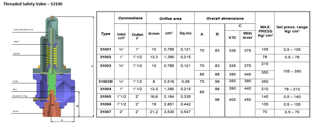
Safety valves have different discharge capacities. These capacities are based on the geometrical area of the body seat upstream and downstream of the valve. Flow diameter is the minimum geometrical diameter upstream and downstream of the body seat.
The nominal size designation refers to the inlet orifice diameter. A safety Valve"s theoretical flowing capacity is the mass flow through an orifice with the same cross-sectional area as the valve"s flow area. This capacity does not account for the flow losses caused by the valve. The actual capacity is measured, and the certified flow capacity is the actual flow capacity reduced by 10%.
A safety valve"s discharge capacity is dependent on the set pressure and position in a system. Once the set pressure is calculated, the discharge capacity must be determined. Safety valves may be oversized or undersized depending on the flow throughput and/or the valve"s set pressure.
The actual discharge capacity of a safety valve depends on the type of discharge system used. In liquid service, safety valves are generally automatic and direct-pressure actuated.
A safety valve is used to protect against overpressure in a fluid system. Its design allows for a lift in the disc, indicating that the valve is about to open. When the inlet pressure rises above the set pressure, the guide moves to the open position, and media flows to the outlet via the pilot tube. Once the inlet pressure falls below the set pressure, the main valve closes and prevents overpressure. There are five criteria for selecting a safety valve.
The first and most basic requirement of a safety valve is its ability to safely control the flow of gas. Hence, the valve must be able to control the flow of gas and water. The valve should be able to withstand the high pressures of the system. This is because the gas or steam coming from the boiler will be condensed and fill the pipe. The steam will then wet the safety valve seat.
The other major requirement for safety valves is their ability to prevent pressure buildup. They prevent overpressure conditions by allowing liquid or gas to escape. Safety valves are used in many different applications. Gas and steam lines, for example, can prevent catastrophic damage to the plant. They are also known as safety relief valves. During an emergency, a safety valve will open automatically and discharge gas or liquid pressure from a pressurized system, preventing it from reaching dangerous levels.
The discharge capacity of a safety valve is based on its orifice area, set pressure, and position in the system. A safety valve"s discharge capacity should be calculated based on the maximum flow through its inlet and outlet orifice areas. Its nominal size is often determined by manufacturer specifications.
Its discharge capacity is the maximum flow through the valve that it can relieve, based on the maximum flow through each individual flow path or combined flow path. The discharge pressure of the safety valve should be more than the operating pressure of the system. As a thumb rule, the relief pressure should be 10% above the working pressure of the system.
It is important to choose the discharge capacity of a safety valve based on the inlet and output piping sizes. Ideally, the discharge capacity should be equal to or greater than the maximum output of the system. A safety valve should also be installed vertically and into a clean fitting. While installing a valve, it is important to use a proper wrench for installation. The discharge piping should slope downward to drain any condensate.
The discharge capacity of a safety valve is measured in a few different ways. The first is the test pressure. This gauge pressure is the pressure at which the valve opens, while the second is the pressure at which it re-closes. Both are measured in a test stand under controlled conditions. A safety valve with a test pressure of 10,000 psi is rated at 10,000 psi (as per ASME PTC25.3).
The discharge capacity of a safety valve should be large enough to dissipate a large volume of pressure. A small valve may be adequate for a smaller system, but a larger one could cause an explosion. In a large-scale manufacturing plant, safety valves are critical for the safety of personnel and equipment. Choosing the right valve size for a particular system is essential to its efficiency.
Before you use a safety valve, you need to know its discharge capacity. Here are some steps you need to follow to calculate the discharge capacity of a safety valve.
To check the discharge capacity of a safety valve, the safety valve should be installed in the appropriate location. Its inlet and outlet pipework should be thoroughly cleaned before installation. It is important to avoid excessive use of PTFE tape and to ensure that the installation is solid. The safety valve should not be exposed to vibration or undue stress. When mounting a safety valve, it should be installed vertically and with the test lever at the top. The inlet connection of the safety valve should be attached to the vessel or pipeline with the shortest length of pipe. It must not be interrupted by any isolation valve. The pressure loss at the inlet of a safety valve should not exceed 3% of the set pressure.
The sizing of a safety valve depends on the amount of fluid it is required to control. The rated discharge capacity is a function of the safety valve"s orifice area, set pressure, and position in the system. Using the manufacturer"s specifications for orifice area and nominal size of the valve, the capacity of a safety valve can be determined. The discharge flow can be calculated using the maximum flow through the valve or the combined flows of several paths. When sizing a safety valve, it"s necessary to consider both its theoretical and actual discharge capacity. Ideally, the discharge capacity will be equal to the minimum area.
To determine the correct set pressure for a safety valve, consider the following criteria. It must be less than the MAAP of the system. Set pressure of 5% greater than the MAAP will result in an overpressure of 10%. If the set pressure is higher than the MAAP, the safety valve will not close. The MAAP must never exceed the set pressure. A set pressure that is too high will result in a poor shutoff after discharge. Depending on the type of valve, a backpressure variation of 10% to 15% of the set pressure cannot be handled by a conventional valve.

The RV10 safety relief valve is well-suited for overpressure protection of production equipment, including compressors, scrubbers, separators, pipelines or anywhere overpressure protection may be required.

Stainless Steel Safety Relief Valve is a safety mechanism deployed in applications to prevent them from bursting under pressure. Suraj Metal Corporationis a leading manufacturer and supplier of the different types such as the Brass Safety Valveand others in various sizes and dimensions. The valves are fitted with the pipelines in a way that when the pressure goes above the threshold level, the Stainless Steel Air Safety Valveopens up and relieves the system of pressure.
This is important to prevent the pipes from being damaged or bursting under high pressure. The Stainless Steel Safety Exhaust Ball Valveis used in the exhaust systems where the temperature plays major role. When the temperature exceeds certain point, it increases pressure and the safety valve opens and balances the pressure in the system. The spring loaded boiler safety valveis used in boilers and heat exchanger systems where steam and hot water are circulated through pipes. There are different gas safety valvetypes and each of these differ in their purpose and functions. Please feel free to contact us for more information on the different types of air compressor pressure relief valveand others with pricing.
We Keep Bulk Stock of CF8 stainless steel Pressure Safety Valve at our stockyard, contact us for Free Sample & stock list, View Brass Safety Valve Dimension chart
find Stainless Steel Safety Exhaust Ball Valve Dimensions, price list, size chart here, Buy ASTM A351 CF8M 316 temperature safety valve at best price in India

Industrial equipment often uses either safety or relief valves to prevent damaging pressure levels from building up. Though they perform similar functions, there are some critical differences between safety and relief valves. Understanding these two valves’ differences is essential for proper pressure system operation. So here we discuss the pressure safety valve vs pressure relief valve.
A pressure relief valve is a device that releases pressure from a system. The relief valve is generally immune to the effects of back pressure and must be periodically stripped down. Pressure relief valves are one the essential parts of a pressure system to prevent system failures. They are set to open at a predetermined pressure level. Each pressure system has a setpoint that is a predetermined limit. The setpoint determines when the valve will open and prevents overpressure.
Pressure relief valves are typically used in gas or liquid systems where there is a need to prevent excessive pressure from building up. When the pressure in the system reaches a certain level, the valve will open and release the pressure. Pressure relief valves are an essential safety feature in many designs and can help to prevent damage to the system or components.
PRVs are generally considered to be safe and reliable devices. However, before installing a PRV in a system, some potential disadvantages should be considered. Here are five pros and cons of pressure relief valves:
Pros: Pressure relief valves are anessential safety feature in many systems. They protect against over-pressurization by relieving excess pressure from the system. This can help to prevent severe damage or even explosions.
Pressure relief valves can help to improve the efficiency of a system. The system can operate at lower overall pressure by relieving excess pressure and saving energy.
Pressure relief valves can be used as a safety device in systems that are susceptible to overpressurization. By relieving pressure before it builds up to a dangerous level, they can help to prevent accidents and injuries.
Cons: Pressure relief valves can be a potential source of leaks. If not properly maintained, the valve may not seat properly and can allow fluids or gasses to escape.
Pressure relief valves can sometimes cause problems if they do not open or close properly. This can lead to process disruptions and may cause safety issues.
A pressure safety valve is a device used to release pressure from a system that has exceeded its design limit. This safety valve is a fail-safe device. This type of valve is typically used in systems that contain fluids or gasses under high pressure. Pressure safety valves are designed to open and release pressure when the system has exceeded its maximum pressure limit. This helps to prevent the system from rupturing or exploding.
Pressure safety valves are an essential part of many different types of systems and can help keep both people and property safe. If anyone is ever in a situation where they need to release pressure from a system, it is essential to know how to use a pressure safety valve correctly.
A pressure safety valve (PSV) is a type used to relieve a system’s pressure. PSVs are commonly used in chemical and process industries, as well as in some kinds of pressure vessels. There are both advantages and disadvantages to using a PSV. Some of the pros of using a PSV include: PSVs can help to prevent overpressurization, which can be dangerous.
A safety valve is a pressure relief device used to prevent the over-pressurization of a system. On the other hand, a relief valve is a device used to relieve pressure from a system that is already overpressurized. Function Of Pressure Relief Valve Vs Safety Valve
The function of a pressure relief valve is to protect a system or component from excess pressure. A safety valve, on the other hand, is designed to protect from overpressurization. Both types of valves are used in various industries, but each has unique benefits and drawbacks.
Pressure relief valves are typically used in systems where a small amount of overpressure can cause damage. On the other hand, safety valves are designed for systems where overpressurization could be catastrophic. Both valves have advantages and disadvantages, so choosing the right type of valve for the specific application is essential.
Relief valves are usually set to open at a specific pressure and will close once the pressure has been relieved. Safety valves are similar in that they are also used to protect equipment from excessive pressure. However, safety valves are designed to stay open until they are manually closed. This is because safety valves are typically used in applications where it is not safe to have a closed valve, such as in a gas line. Operation Of Safety Relief Valve Vs Pressure Relief Valve
Two types of valves are commonly used in industrial settings: relief valves and safety valves. Both of these valves serve essential functions, but they operate in different ways.
Relief valves are designed to relieve pressure build-up in a system. They open when the system pressure reaches a certain point, which allows excess pressure to be released. On the other hand, safety valves are designed to prevent accidents by preventing system pressure from getting too high. They open when the system pressure reaches a certain point, which allows excess pressure to be released before an accident can occur.
So, which valve is better? That depends on the situation. A relief valve is the better option to protect the system from pressure build-up. If anyone need to protect the system from accidents, then a safety valve is the better option Setpoint Of Pressure Relief Valve Vs Safety Relief Valve
The relief valve is made to open when it reaches a specific pressure, commonly described as a “setpoint”. Setpoints shouldn’t be misinterpreted as the pressure set. A setpoint on a relief valve is set to the lowest possible pressure rating, which means it is set to the lowest system pressure before an overpressure situation is observed. The valve will open as the pressure increases to a point higher than the setpoint. The setting point is determined as pounds per square inch (PSIG) and should be within the maximum allowed operating pressure (MAWP) limits. In safety valves, the setpoint is typically placed at about 3 percent over the working pressure level, whereas relief valves are determined at 10 percent.
No, the safety valve and relief valve can not be used interchangeably. Though both valves are seal butterfly valve and used for safety purposes, they serve different functions. A safety valve relieves excess pressure that builds up in a system, while a relief valve regulates the pressure in a system.
Knowing the difference between these two types of valves is essential, as using the wrong valve for the intended purpose can potentially be dangerous. If unsure which type of valve to use, it is always best to consult with a professional.
A few key points help us understand the safety valve vs pressure relief valve. Safety valves are designed to relieve pressure in a system when it gets too high, while relief valves are designed to relieve pressure when it gets too low. Safety valves are usually set to open at a specific pressure, while relief valves are generally open at a particular vacuum. Safety valves are typically intended for one-time use, while relief valves can be used multiple times. Choose the trusted valve manufactureraccording to the specific business needs.

Providing you the best range of cast steel safety relief valves, open bonnet safety relief valve, stainless steel safety relief valve, flange end pressure relief valves, safety relief valve and pressure safety valve with effective & timely delivery.

BSP/NPT connection Pressure safety relief valves are typically used to control pressure on boilers in heating systems, on stored hot water cylinders in domestic hot water systems, and generally in water systems.
When the calibrated pressure is reached, the valve opens and, using discharge to the atmosphere, prevents the pressure of the system from reaching levels that would be dangerous for the boiler and the components in the system itself.
The brass safety relief valve is a piece of equipment found in industrial settings. The valve has two functions: release pressure and protect against over-pressure situations. These valves are designed for steam, water, gas, or other liquids that may expand when removed from the pipe. They can be found on boilers and pressure vessels such as pipelines; they will often be placed at an elevation high enough above the ground so that a rupture won’t cause any damage. These valves have many features.
Brass Safety Relief Valve with DN15 NPT female inlet and 1/2″ male outlet. This is a great safety valve for water tanks. It has a 200 PSI pressure rating, making it perfect to work with your tank!
This product is designed to work for water tanks. It has a brass body, which makes it durable and sturdy. The safety relief valve helps prevent damage caused by excessive pressure build-up in the tank during use. It is easy to install and can be used with any water tank.
The Brass Safety Relief Valve is designed for use in water tanks, as it has a 2″ female NPT connection. The valve features a solid brass body and bonnet, which can withstand high temperatures of up to 200°F (93°C). This relief valve also features a 1/2″ male NPT connection that can be used with the discharge hose.
The Brass Safety Relief Valve should be installed on the bottom or side of your water tank. You will need to drill an opening in your tank to install this safety device.
Brass Safety Relief Valve is a type of safety valve that prevents the tank from over-pressurization. The brass safety relief valve has a spring-loaded poppet that opens when the pressure in the tank rises above a predetermined value. It can be installed on water tanks, boilers, and other pressure vessels.
1) Brass Safety Relief Valve is easy to install, with no need for flanges or welding. It can be mounted in any position and does not require the pipework to seal off the rest of the system.
The Brass Safety Relief Valve is a safety device to prevent the over-pressurization of water tanks and piping. The valve closes when the pressure reaches a certain level, preventing damage to the equipment. It also prevents flooding and allows for easy maintenance by opening when needed. This brass relief valve is designed for hot and cold water and fire sprinkler systems. Operating at a temperature range of -40 degrees F to 180 degrees F, it can be used in residential or commercial settings.
SAFECON - Series SC- 5000 SAFETY / PRESSURE RELIEF VALVES are designed and manufactured in compliance with API 520 / ASME Section Vlll Division l for High performance application for use on vapor, gas and liquid for over pressure protection. This Conventional safety / pressure relief valves are versatile, safe & interchangeable.
The primary purpose of a safety valve is to protect life, property and the environment. Safety valves are designed to open and release excess pressure from vessels or equipment and then close again.
The function of safety valves differs depending on the load or main type of the valve. The main types of safety valves are spring-loaded, weight-loaded and controlled safety valves.
Regardless of the type or load, safety valves are set to a specific set pressure at which the medium is discharged in a controlled manner, thus preventing overpressure of the equipment. In dependence of several parameters such as the contained medium, the set pressure is individual for each safety application.

Industrial Safety ValveManufacturer of a wide range of products which include 1/2 inch gun metal safety valve, gun metal pressure safety valve, brass air release valve, pressure safety relief valve, 1/4 inch pressure relief valve and 1 inch pressure safety valves.
We offer 1/2 Inch Gun Metal Safety Valveopen discharge as well as in enclosed body also known as angle type safety valve or pressure release safety valve, which are ideal for compressible fluids like steam, gas, or vapor. Safety valves are suitable for application areas where high pressure and capacity is required. Our precision engineered safety valves are appreciated for high capacity level, durable finish, and industry competitive price.
We are leading manufacturer and supplier of the Butterfly Valves,Industrial Valves,Gate Valve,Globe Valve,Strainer,Ball Valve,Disc Check Valve,Check Valve,Needle Valve,Gauge Glass Cock Valve Etc.
We are leading manufacturer and supplier of the Butterfly Valves,Industrial Valves,Gate Valve,Globe Valve,Strainer,Ball Valve,Disc Check Valve,Check Valve,Needle Valve,Gauge Glass Cock Valve Etc.
We offer 800 mm Pressure Safety Relief Valve open discharge as well as in enclosed body also known as angle type safety valve or pressure release safety valve, which are ideal for compressible fluids like steam, gas, or vapor.
We offer gun metal1/4 Inch Pressure Relief Valveopen discharge as well as in enclosed body also known as angle type safety valve or pressure release safety valve, which are ideal for compressible fluids like steam, gas, or vapor. Safety valves are suitable for application areas where high pressure and capacity is required.
We offer gun metal1 Inch Pressure Safety Valvesopen discharge as well as in enclosed body also known as angle type safety valve or pressure release safety valve, which are ideal for compressible fluids like steam, gas, or vapor. Safety valves are suitable for application areas where high pressure and capacity is required. Our precision engineered safety valves are appreciated for high capacity level, durable finish, and industry competitive price.
We are leading manufacturer and supplier of the Butterfly Valves,Industrial Valves,Gate Valve,Globe Valve,Strainer,Ball Valve,Disc Check Valve,Check Valve,Needle Valve,Gauge Glass Cock Valve Etc.
We are leading manufacturer and supplier of the Butterfly Valves,Industrial Valves,Gate Valve,Globe Valve,Strainer,Ball Valve,Disc Check Valve,Check Valve,Needle Valve,Gauge Glass Cock Valve Etc.
We are leading manufacturer and supplier of the Butterfly Valves,Industrial Valves,Gate Valve,Globe Valve,Strainer,Ball Valve,Disc Check Valve,Check Valve,Needle Valve,Gauge Glass Cock Valve Etc.
We are leading manufacturer and supplier of the Butterfly Valves,Industrial Valves,Gate Valve,Globe Valve,Strainer,Ball Valve,Disc Check Valve,Check Valve,Needle Valve,Gauge Glass Cock Valve Etc.9
We are leading manufacturer and supplier of the Butterfly Valves,Industrial Valves,Gate Valve,Globe Valve,Strainer,Ball Valve,Disc Check Valve,Check Valve,Needle Valve,Gauge Glass Cock Valve Etc.
We are leading manufacturer and supplier of the Butterfly Valves,Industrial Valves,Gate Valve,Globe Valve,Strainer,Ball Valve,Disc Check Valve,Check Valve,Needle Valve,Gauge Glass Cock Valve Etc.
We are leading manufacturer and supplier of the Butterfly Valves,Industrial Valves,Gate Valve,Globe Valve,Strainer,Ball Valve,Disc Check Valve,Check Valve,Needle Valve,Gauge Glass Cock Valve Etc.
A safety valve is a valve that acts as a fail-safe. An example of safety valve is a pressure relief valve (PRV), which automatically releases a substance from a boiler, pressure vessel, or other system, when the pressure or temperature exceeds preset limits. Pilot-operated relief valves are a specialized type of pressure safety valve. A leak tight, lower cost, single emergency use option would be a rupture disk.
Safety valves were first developed for use on steam boilers during the Industrial Revolution. Early boilers operating without them were prone to explosion unless carefully operated.
Vacuum safety valves (or combined pressure/vacuum safety valves) are used to prevent a tank from collapsing while it is being emptied, or when cold rinse water is used after hot CIP (clean-in-place) or SIP (sterilization-in-place) procedures. When sizing a vacuum safety valve, the calculation method is not defined in any norm, particularly in the hot CIP / cold water scenario, but some manufacturers
The earliest and simplest safety valve was used on a 1679 steam digester and utilized a weight to retain the steam pressure (this design is still commonly used on pressure cookers); however, these were easily tampered with or accidentally released. On the Stockton and Darlington Railway, the safety valve tended to go off when the engine hit a bump in the track. A valve less sensitive to sudden accelerations used a spring to contain the steam pressure, but these (based on a Salter spring balance) could still be screwed down to increase the pressure beyond design limits. This dangerous practice was sometimes used to marginally increase the performance of a steam engine. In 1856, John Ramsbottom invented a tamper-proof spring safety valve that became universal on railways. The Ramsbottom valve consisted of two plug-type valves connected to each other by a spring-laden pivoting arm, with one valve element on either side of the pivot. Any adjustment made to one of valves in an attempt to increase its operating pressure would cause the other valve to be lifted off its seat, regardless of how the adjustment was attempted. The pivot point on the arm was not symmetrically between the valves, so any tightening of the spring would cause one of the valves to lift. Only by removing and disassembling the entire valve assembly could its operating pressure be adjusted, making impromptu "tying down" of the valve by locomotive crews in search of more power impossible. The pivoting arm was commonly extended into a handle shape and fed back into the locomotive cab, allowing crews to "rock" both valves off their seats to confirm they were set and operating correctly.
Safety valves also evolved to protect equipment such as pressure vessels (fired or not) and heat exchangers. The term safety valve should be limited to compressible fluid applications (gas, vapour, or steam).
For liquid-packed vessels, thermal relief valves are generally characterized by the relatively small size of the valve necessary to provide protection from excess pressure caused by thermal expansion. In this case a small valve is adequate because most liquids are nearly incompressible, and so a relatively small amount of fluid discharged through the relief valve will produce a substantial reduction in pressure.
Flow protection is characterized by safety valves that are considerably larger than those mounted for thermal protection. They are generally sized for use in situations where significant quantities of gas or high volumes of liquid must be quickly discharged in order to protect the integrity of the vessel or pipeline. This protection can alternatively be achieved by installing a high integrity pressure protection system (HIPPS).
In the petroleum refining, petrochemical, chemical manufacturing, natural gas processing, power generation, food, drinks, cosmetics and pharmaceuticals industries, the term safety valve is associated with the terms pressure relief valve (PRV), pressure safety valve (PSV) and relief valve.
The generic term is Pressure relief valve (PRV) or pressure safety valve (PSV). PRVs and PSVs are not the same thing, despite what many people think; the difference is that PSVs have a manual lever to open the valve in case of emergency.
Relief valve (RV): an automatic system that is actuated by the static pressure in a liquid-filled vessel. It specifically opens proportionally with increasing pressure
Pilot-operated safety relief valve (POSRV): an automatic system that relieves on remote command from a pilot, to which the static pressure (from equipment to protect) is connected
Low pressure safety valve (LPSV): an automatic system that relieves static pressure on a gas. Used when the difference between the vessel pressure and the ambient atmospheric pressure is small.
Vacuum pressure safety valve (VPSV): an automatic system that relieves static pressure on a gas. Used when the pressure difference between the vessel pressure and the ambient pressure is small, negative and near to atmospheric pressure.
Low and vacuum pressure safety valve (LVPSV): an automatic system that relieves static pressure on a gas. Used when the pressure difference is small, negative or positive and near to atmospheric pressure.
In most countries, industries are legally required to protect pressure vessels and other equipment by using relief valves. Also, in most countries, equipment design codes such as those provided by the ASME, API and other organizations like ISO (ISO 4126) must be complied with. These codes include design standards for relief valves and schedules for periodic inspection and testing after valves have been removed by the company engineer.
Today, the food, drinks, cosmetics, pharmaceuticals and fine chemicals industries call for hygienic safety valves, fully drainable and Cleanable-In-Place. Most are made of stainless steel; the hygienic norms are mainly 3A in the USA and EHEDG in Europe.
The first safety valve was invented by Denis Papin for his steam digester, an early pressure cooker rather than an engine.steelyard" lever a smaller weight was required, also the pressure could easily be regulated by sliding the same weight back and forth along the lever arm. Papin retained the same design for his 1707 steam pump.Greenwich in 1803, one of Trevithick"s high-pressure stationary engines exploded when the boy trained to operate the engine left it to catch eels in the river, without first releasing the safety valve from its working load.
Although the lever safety valve was convenient, it was too sensitive to the motion of a steam locomotive. Early steam locomotives therefore used a simpler arrangement of weights stacked directly upon the valve. This required a smaller valve area, so as to keep the weight manageable, which sometimes proved inadequate to vent the pressure of an unattended boiler, leading to explosions. An even greater hazard was the ease with which such a valve could be tied down, so as to increase the pressure and thus power of the engine, at further risk of explosion.
Although deadweight safety valves had a short lifetime on steam locomotives, they remained in use on stationary boilers for as long as steam power remained.
Weighted valves were sensitive to bouncing from the rough riding of early locomotives. One solution was to use a lightweight spring rather than a weight. This was the invention of Timothy Hackworth on his leaf springs.
These direct-acting spring valves could be adjusted by tightening the nuts retaining the spring. To avoid tampering, they were often shrouded in tall brass casings which also vented the steam away from the locomotive crew.
The Salter coil spring spring balance for weighing, was first made in Britain by around 1770.spring steels to make a powerful but compact spring in one piece. Once again by using the lever mechanism, such a spring balance could be applied to the considerable force of a boiler safety valve.
The spring balance valve also acted as a pressure gauge. This was useful as previous pressure gauges were unwieldy mercury manometers and the Bourdon gauge had yet to be invented.
Paired valves were often adjusted to slightly different pressures too, a small valve as a control measure and the lockable valve made larger and permanently set to a higher pressure, as a safeguard.Sinclair for the Eastern Counties Railway in 1859, had the valve spring with pressure scale behind the dome, facing the cab, and the locked valve ahead of the dome, out of reach of interference.
In 1855, John Ramsbottom, later locomotive superintendent of the LNWR, described a new form of safety valve intended to improve reliability and especially to be tamper-resistant. A pair of plug valves were used, held down by a common spring-loaded lever between them with a single central spring. This lever was characteristically extended rearwards, often reaching into the cab on early locomotives. Rather than discouraging the use of the spring lever by the fireman, Ramsbottom"s valve encouraged this. Rocking the lever freed up the valves alternately and checked that neither was sticking in its seat.
A drawback to the Ramsbottom type was its complexity. Poor maintenance or mis-assembly of the linkage between the spring and the valves could lead to a valve that no longer opened correctly under pressure. The valves could be held against their seats and fail to open or, even worse, to allow the valve to open but insufficiently to vent steam at an adequate rate and so not being an obvious and noticeable fault.Rhymney Railway, even though the boiler was almost new, at only eight months old.
Naylor valves were introduced around 1866. A bellcrank arrangement reduced the strain (percentage extension) of the spring, thus maintaining a more constant force.L&Y & NER.
All of the preceding safety valve designs opened gradually and had a tendency to leak a "feather" of steam as they approached "blowing-off", even though this was below the pressure. When they opened they also did so partially at first and didn"t vent steam quickly until the boiler was well over pressure.
The quick-opening "pop" valve was a solution to this. Their construction was simple: the existing circular plug valve was changed to an inverted "top hat" shape, with an enlarged upper diameter. They fitted into a stepped seat of two matching diameters. When closed, the steam pressure acted only on the crown of the top hat, and was balanced by the spring force. Once the valve opened a little, steam could pass the lower seat and began to act on the larger brim. This greater area overwhelmed the spring force and the valve flew completely open with a "pop". Escaping steam on this larger diameter also held the valve open until pressure had dropped below that at which it originally opened, providing hysteresis.
These valves coincided with a change in firing behaviour. Rather than demonstrating their virility by always showing a feather at the valve, firemen now tried to avoid noisy blowing off, especially around stations or under the large roof of a major station. This was mostly at the behest of stationmasters, but firemen also realised that any blowing off through a pop valve wasted several pounds of boiler pressure; estimated at 20 psi lost and 16 lbs or more of shovelled coal.
Pop valves derived from Adams"s patent design of 1873, with an extended lip. R. L. Ross"s valves were patented in 1902 and 1904. They were more popular in America at first, but widespread from the 1920s on.
Although showy polished brass covers over safety valves had been a feature of steam locomotives since Stephenson"s day, the only railway to maintain this tradition into the era of pop valves was the GWR, with their distinctive tapered brass safety valve bonnets and copper-capped chimneys.
Developments in high-pressure water-tube boilers for marine use placed more demands on safety valves. Valves of greater capacity were required, to vent safely the high steam-generating capacity of these large boilers.Naylor valve) became more critical.distilled feedwater and also a scouring of the valve seats, leading to wear.
High-lift safety valves are direct-loaded spring types, although the spring does not bear directly on the valve, but on a guide-rod valve stem. The valve is beneath the base of the stem, the spring rests on a flange some height above this. The increased space between the valve itself and the spring seat allows the valve to lift higher, further clear of the seat. This gives a steam flow through the valve equivalent to a valve one and a half or twice as large (depending on detail design).
The Cockburn Improved High Lift design has similar features to the Ross pop type. The exhaust steam is partially trapped on its way out and acts on the base of the spring seat, increasing the lift force on the valve and holding the valve further open.
To optimise the flow through a given diameter of valve, the full-bore design is used. This has a servo action, where steam through a narrow control passage is allowed through if it passes a small control valve. This steam is then not exhausted, but is passed to a piston that is used to open the main valve.
There are safety valves known as PSV"s and can be connected to pressure gauges (usually with a 1/2" BSP fitting). These allow a resistance of pressure to be applied to limit the pressure forced on the gauge tube, resulting in prevention of over pressurisation. the matter that has been injected into the gauge, if over pressurised, will be diverted through a pipe in the safety valve, and shall be driven away from the gauge.
There is a wide range of safety valves having many different applications and performance criteria in different areas. In addition, national standards are set for many kinds of safety valves.
Safety valves are required on water heaters, where they prevent disaster in certain configurations in the event that a thermostat should fail. Such a valve is sometimes referred to as a "T&P valve" (Temperature and Pressure valve). There are still occasional, spectacular failures of older water heaters that lack this equipment. Houses can be leveled by the force of the blast.
Pressure cookers are cooking pots with a pressure-proof lid. Cooking at pressure allows the temperature to rise above the normal boiling point of water (100 degrees Celsius at sea level), which speeds up the cooking and makes it more thorough.
Pressure cookers usually have two safety valves to prevent explosions. On older designs, one is a nozzle upon which a weight sits. The other is a sealed rubber grommet which is ejected in a controlled explosion if the first valve gets blocked. On newer generation pressure cookers, if the steam vent gets blocked, a safety spring will eject excess pressure and if that fails, the gasket will expand and release excess pressure downwards between the lid and the pan. Also, newer generation pressure cookers have a safety interlock which locks the lid when internal pressure exceeds atmospheric pressure, to prevent accidents from a sudden release of very hot steam, food and liquid, which would happen if the lid were to be removed when the pan is still slightly pressurised inside (however, the lid will be very hard or impossible to open when the pot is still pressurised).
These figures are based on two measurements, a drop from 225 psi to 205 psi for an LNER Class V2 in 1952 and a smaller drop of 10 psi estimated in 1953 as 16 lbs of coal.
"Trial of HMS Rattler and Alecto". April 1845. The very lowest pressure exhibited "when the screw was out of the water" (as the opponents of the principle term it) was 34 lb, ranging up to 60 lb., on Salter"s balance.

Safety valves English safety valve is an industrial valve product, whose main function is to protect the pipeline from pressure surge beyond the rated value. During work, it is always in the closed state. When the inlet pressure exceeds the rated value, the valve opens to allow some liquid to flow through and recirculate to the container. The safety valve operates on the Bernoulli principle.
Safety valve and pressure relief valve are two types of valves with completely different features, but some people still confuse these two types of valves, so to compare the differences between them, people can follow the table below. down here.
The main function is to release pressure in the system, helping to prevent overpressure from occurring in the system. It helps to prevent pipeline breakage in the system, damage to equipment, and helps protect human life from the effects of the system if it is overpressured.
Valve shaft: Connected to the valve disc, is a straight shaft made from high-strength materials, the main function of which is to support the opening and closing of the valve disc.
Valve body: Has a structure of an inlet and an outlet port connected to the main pipe, which is a pressure reducing pipe and an exhaust pipe to let the fluid flow to the tank. Valve body is usually made from materials such as stainless steel, copper, cast iron, steel ...
Spring: Using the elastic force of the spring to adjust the valve to open and close for pressure relief, the spring can change the compression through an adjustment screw.
Valve cover: Connected to the valve body by bolts, making the valve tight and easy to maintain, this cover is usually made of the same material as the valve body.
Adjustment screw: The adjusting screw is a part used to adjust the set pressure for the safety valve, it will directly adjust the compression of the spring.
When the pressure passing through the pipe exceeds the rated pressure to which this safety valve is preset, the pressure level of this flow exceeds the compression force of the spring. The piston will be pushed up, the safety valve is opened to discharge the fluid, excess pressure to the outside or be connected to the pipe connecting the tank to discharge to the tank. This helps to reduce the pressure.
When the pressure level in the pipeline returns to normal, the piston is pushed back to the original position, the safety valve will close completely.
Valve body: The valve body is usually made up of materials such as cast iron, copper, stainless steel, steel, etc. This valve body also has two installation ports, the inlet and outlet ports.
Auxiliary valve spring: The spring of the auxiliary valve is designed with great rigidity, which is the main part of this safety valve to adjust the set pressure of the safety valve.
Main valve spring: The spring of the main valve has a design with less stiffness than the spring of the auxiliary valve. The spring of the main valve is connected together with the piston.
Piston: A detail that closes and opens the valve"s outlet, through this part, the fluid can be discharged when overpressure or blocked when the pressure returns to normal pressure.
When the pressure in the system is below the set rating. Both the auxiliary valve and the main valve of the safety valve will be in the closed state. The higher the pressure, the greater the pressure in the upper chamber of the piston, the tighter the piston is closed (under pressure conditions below rated pressure).
When the pressure is above the rated pressure, the auxiliary valve opens, releasing the pressure in the chamber above the piston. At this time, the pressure under the piston is greater than the pressure above the piston, so the piston is pushed up, releasing the pressure in the system through the exhaust port.
When the pressure in the system returns to the pressure level below the rated pressure, the auxiliary valve closes and the main valve closes, the cycle repeats the same.
These safety valve products are mainly because of their compact, simpler design, which helps to reduce structural materials, so the cost will also be lower than indirect-acting safety valve products.
Designed with an extra valve to adjust the valve, these safety valves have a more moderate pressure release, are easier to adjust, have multiple pressure settings, and can set the rated pressure to a high level. than.
These full valves often have a more complicated structure, more details and more parts, which often makes it more difficult to maintain, service and repair the valve if the valve fails.
These indirect-acting safety valves are more suitable for clean, treated fluid applications, their auxiliary valves are often quite sensitive to dirt and are prone to clogging.
Composed of conventional cast iron material lines, ductile cast iron materials. For good heat resistance, it can work with temperatures up to 220 degrees Celsius and the durability of this material is quite good.
It is made of stainless steel material, so it has anti-corrosion, anti-rust, besides this material line is also capable of working in high temperature, high pressure and very good durability. .
It is a flange connection type product. As is known, flange connection types are usually designed for large sizes only. It offers both quick disassembly and good sealing, used in high pressure applications.
Designed with threaded connection. This type of valve is usually produced with a smaller size, with the characteristics of being compact and simple. For quick and convenient installation.
Designed with a recoil arm, which is directly linked to the valve shaft. This product will help to release pressure directly manually in case of emergency.
In the field of oil and gas, oil and gas industry, valves are used with the main purpose to discharge toxic substances to help prevent fire and explosion.
Currently, safety valves have a very diverse design, so choosing the right product for certain applications is not difficult. So, here are some tips to keep in mind:
Next, it is necessary to consider what type of system the application is (steam, gas or liquid systems). Because these fluids will have their own characteristics and valves will also have separate designs.
For example: In compressed air applications where the gas can be discharged directly to the environment, a valve with an open bonnet can be selected. For applications where liquid is discharged to the tank, or gaseous fluids are not allowed to be discharged into the environment, it is necessary to use a valve with a tight bonnet.
The structure of the valve is a factor to consider in the selection process. Valves with different structures have different characteristics and applications.
Performance is a factor to consider, valve performance requirements will vary from application to application which is why it is important to choose the right valve.
Standard requirements, safety valve standards are often concerned, because it is related to structure and performance. This standard is generally approved by independent bodies.
Maximum allowable working pressure: This pressure level is the safe level of the system, that is, at this level the system still works safely, but if it exceeds this level, the system will overpressure. .
Maximum allowable cumulative pressure: is the maximum pressure level that the system is allowed to reach. Usually expressed as a percentage of the maximum allowable working pressure.
After determining the set pressure of the valve, we proceed to set the set pressure through the adjustment part which is the adjusting screw on the valve body.
It is necessary to flush the pipeline before installation, to avoid the accumulation of impurities and dirt that are the factors that cause damage to the details in the valve.
These valves need to be installed according to their installation standards, with different connection types the installation standards of these types will be different.
Leaks are often caused by a number of reasons such as: incorrect installation, faulty gaskets in the valve, making the valve unable to close properly. The condition of impurities and dirt mixed in the fluid can cause blockage, causing the valve to not close properly.
Failure to close or open error. The reason is that valves have discs stuck in the open position, unable to close, which causes fluid loss. Valves that do not open are discs stuck in the closed position, causing the valve to not work, which prevents the system from releasing excess pressure and endangers the system.
To prolong the life of the valve, the best way is to maintain and maintain the valve regularly and properly. Recommended maintenance period is at least once every 12 months.


 8613371530291