
at what psi is the safety valve set to open supplier
Finding a quality driving school in can be a difficult and time consuming task. driving-schools.com comprehensive database of driving schools helps you pick one that’s right for you.
In an air brake system, the first tank that receives compressed air has a safety valve that releases air if the pressure gets too high. It is usually set to open at 150 psi. If the valve must open, there is a fault in the system that should be repaired by a mechanic.
In order to ensure that the maximum allowable accumulation pressure of any system or apparatus protected by a safety valve is never exceeded, careful consideration of the safety valve’s position in the system has to be made. As there is such a wide range of applications, there is no absolute rule as to where the valve should be positioned and therefore, every application needs to be treated separately.
A common steam application for a safety valve is to protect process equipment supplied from a pressure reducing station. Two possible arrangements are shown in Figure 9.3.3.
The safety valve can be fitted within the pressure reducing station itself, that is, before the downstream stop valve, as in Figure 9.3.3 (a), or further downstream, nearer the apparatus as in Figure 9.3.3 (b). Fitting the safety valve before the downstream stop valve has the following advantages:
• The safety valve can be tested in-line by shutting down the downstream stop valve without the chance of downstream apparatus being over pressurised, should the safety valve fail under test.
• When setting the PRV under no-load conditions, the operation of the safety valve can be observed, as this condition is most likely to cause ‘simmer’. If this should occur, the PRV pressure can be adjusted to below the safety valve reseat pressure.
• Any additional take-offs downstream are inherently protected. Only apparatus with a lower MAWP requires additional protection. This can have significant cost benefits.
Indeed, a separate safety valve may have to be fitted on the inlet to each downstream piece of apparatus, when the PRV supplies several such pieces of apparatus.
• If supplying one piece of apparatus, which has a MAWP pressure less than the PRV supply pressure, the apparatus must be fitted with a safety valve, preferably close-coupled to its steam inlet connection.
• If a PRV is supplying more than one apparatus and the MAWP of any item is less than the PRV supply pressure, either the PRV station must be fitted with a safety valve set at the lowest possible MAWP of the connected apparatus, or each item of affected apparatus must be fitted with a safety valve.
• The safety valve must be located so that the pressure cannot accumulate in the apparatus viaanother route, for example, from a separate steam line or a bypass line.
It could be argued that every installation deserves special consideration when it comes to safety, but the following applications and situations are a little unusual and worth considering:
• Fire - Any pressure vessel should be protected from overpressure in the event of fire. Although a safety valve mounted for operational protection may also offer protection under fire conditions,such cases require special consideration, which is beyond the scope of this text.
• Exothermic applications - These must be fitted with a safety valve close-coupled to the apparatus steam inlet or the body direct. No alternative applies.
• Safety valves used as warning devices - Sometimes, safety valves are fitted to systems as warning devices. They are not required to relieve fault loads but to warn of pressures increasing above normal working pressures for operational reasons only. In these instances, safety valves are set at the warning pressure and only need to be of minimum size. If there is any danger of systems fitted with such a safety valve exceeding their maximum allowable working pressure, they must be protected by additional safety valves in the usual way.
In order to illustrate the importance of the positioning of a safety valve, consider an automatic pump trap (see Block 14) used to remove condensate from a heating vessel. The automatic pump trap (APT), incorporates a mechanical type pump, which uses the motive force of steam to pump the condensate through the return system. The position of the safety valve will depend on the MAWP of the APT and its required motive inlet pressure.
This arrangement is suitable if the pump-trap motive pressure is less than 1.6 bar g (safety valve set pressure of 2 bar g less 0.3 bar blowdown and a 0.1 bar shut-off margin). Since the MAWP of both the APT and the vessel are greater than the safety valve set pressure, a single safety valve would provide suitable protection for the system.
However, if the pump-trap motive pressure had to be greater than 1.6 bar g, the APT supply would have to be taken from the high pressure side of the PRV, and reduced to a more appropriate pressure, but still less than the 4.5 bar g MAWP of the APT. The arrangement shown in Figure 9.3.5 would be suitable in this situation.
Here, two separate PRV stations are used each with its own safety valve. If the APT internals failed and steam at 4 bar g passed through the APT and into the vessel, safety valve ‘A’ would relieve this pressure and protect the vessel. Safety valve ‘B’ would not lift as the pressure in the APT is still acceptable and below its set pressure.
It should be noted that safety valve ‘A’ is positioned on the downstream side of the temperature control valve; this is done for both safety and operational reasons:
Operation - There is less chance of safety valve ‘A’ simmering during operation in this position,as the pressure is typically lower after the control valve than before it.
Also, note that if the MAWP of the pump-trap were greater than the pressure upstream of PRV ‘A’, it would be permissible to omit safety valve ‘B’ from the system, but safety valve ‘A’ must be sized to take into account the total fault flow through PRV ‘B’ as well as through PRV ‘A’.
A pharmaceutical factory has twelve jacketed pans on the same production floor, all rated with the same MAWP. Where would the safety valve be positioned?
One solution would be to install a safety valve on the inlet to each pan (Figure 9.3.6). In this instance, each safety valve would have to be sized to pass the entire load, in case the PRV failed open whilst the other eleven pans were shut down.
If additional apparatus with a lower MAWP than the pans (for example, a shell and tube heat exchanger) were to be included in the system, it would be necessary to fit an additional safety valve. This safety valve would be set to an appropriate lower set pressure and sized to pass the fault flow through the temperature control valve (see Figure 9.3.8).

A: Maintenance should be performed on a regular basis. An initial inspection interval of no longer than 12 months is recommended. The user must establish an appropriate inspection interval depending on the service conditions, the condition of the valve and the level of performance desired.
The ASME Boiler and Pressure Vessel Code does not require nor address testing installed valves. The only thing the code states are design and installation requirements, such as some valves must have a lifting lever. For instance for Section VIII:
“Each pressure relief valve on air, water over 140° F, or steam service shall have a substantial lifting device which when activated will release the seating force on the disk when the pressure relief valve is subjected to a pressure of at least 75% of the set pressure of the valve.”
A: This drain hole is required on some models by the ASME Boiler and Pressure Vessel Code. It is intended to prevent any condensate from accumulating in the body that may freeze or corrode internal valve parts and prevent the valve from opening. The drain hole should be piped away to safely dispose of any discharge or condensate.
A: This is often a confusing topic. The correct installation often looks backwards from what appears to be correct. A paper instruction tag illustrating the proper connection is attached to each valve. Vacuum valves should have the NPT threads that are cast integral to the body attached to the vacuum source. See the assembly drawing for additional clarification.
A: Typically, the valve should be nameplate set to open at the MAWP (Maximum Allowable Working Pressure) of the vessel the valve is intended to protect. There is a tolerance to actual set pressure, which means a valve set at 100 psig nameplate may open slightly above or below 100 psig. Consult the current ASME Boiler and Pressure Vessel Code for tolerance classes and special situations when the set pressure may be different than the MAWP.
A: It is normal for spring-operated safety valves to exhibit leakage or simmer/warn, as the system operating pressure approaches the nameplate set pressure, typically in the 80%-90% range of nameplate set pressure. The ASME Boiler and Pressure Vessel Code does not require a specific seat tightness requirement. A certain level of leakage is allowed per manufacturers’ literature and API-527 Seat Tightness Performance Standards, both of which can be found in the Technical Reference Catalog and in the Data Supplement, summarized as follows:
Factory Standard Seat Tightness Performance: No visible (no audible for air service) leakage for 15 seconds (30 seconds for liquid or Section IV steam service) at 20% below nameplate set, or 5 psig below nameplate set, whichever is greater. EXCEPTION: Section IV steam service is checked at 12 psig.
API-527 Standard Seat Tightness Performance: A Functional Test Report (FTR) is automatically provided for valves ordered to API-527. See API 527 for complete details.
At very low set pressures, the ratio of the downward spring force as compared to the upward pressure force is very small. In these cases it may be impossible to achieve seat tightness.
Use soft seats for superior seat tightness, assuming the application falls within the soft seat temperature limitations. Although soft seats will typically provide a higher degree of seat tightness than metal seats, Factory Standard does not ensure bubble-tight seats, regardless of seat material.
A: Maintain a minimum operating gap of 10% between the system operating pressure and the safety valve’s nameplate set pressure. Since direct spring-operated safety valves may “simmer” or “warn” at 90% of the nameplate set pressure, and since the factory standard leak test is performed at 80% of nameplate set pressure, better seat tightness performance can be expected with an operating gap of 20%.
A: It may not be. Warn/simmer or seat leakage is sometimes mistaken for set pressure. Visible or audible leakage or system pressure drop is not set pressure. The correct definition of set pressure is:
Variance of set pressure is allowed, i.e., a Section VIII air valve with a nameplate of 100 psig set pressure may open from 97 psig to 103 psig, but will be factory set around 102 psig.
Gage issues may lead to incorrect reporting of set pressure. Ensure the gage is within calibration and is accurate for the pressure being measured. Rapid increases in system pressure (more than 2 psig/second, water hammer, reciprocating pumps) can make the valve appear to be opening early because the gage cannot accurately report the pressure to which the valve is exposed.
A: Yes. Section I valves have more stringent setting blowdown requirements and may be used in Section VIII steam applications since they meet all the requirements as specified in Section VIII UG-125(a) “Pressure Relief Devices,” which states pressure relief devices must be “in accordance with the requirements of UG-125 through UG-137.” In addition, UG-125(b) actually specifies that even unfired steam boilers MUST use a Section I pressure relief device.
A: Section VIII UG-136(a)(3) states, “Each pressure relief valve on air, water over 140° F (60° C), or steam service shall have a substantial lifting device which when activated will release the seating force on the disk when the pressure relief valve is subjected to a pressure of at least 75% of the set pressure of the valve.”
The user has a documented procedure and an associated implementation program for the periodic removal of the pressure relief valves for inspection and testing, and repair as necessary.
A: Back pressure reduces set pressure on a one-to-one basis, i.e., a valve set at 100 psig subjected to a backpressure at the outlet of 10 psig will not actuate until system pressure reaches 110 psig. Back pressure drastically reduces capacity; typically backpressure of 10% of set pressure will decrease capacity by 50%. Specific capacity reduction should be determined by the user on a case-by-case basis by flow testing. Back pressure in excess of 10% of set pressure is not recommended.
A: The ASME Boiler and Pressure Vessel Code does not have blowdown requirements for Section VIII (or non-code) valves. Blowdown may vary from less than 2% to more than 50%, depending on many factors including: valve design, dimensional tolerance variation, where the set pressure falls in the set pressure range of a spring, spring rate/force ratio, warn ring/guide settings, etc. Typical blowdown for most valves is 15% to 30%, but cannot be guaranteed. VM
Jim Knox is president, Allied Valve, Inc. (www.alliedvalve.com), a valve repair service company and supplier of Tyco Kunkle and Dresser Consolidated safety valves in the Midwest. Reach him at knoxj@alliedvalveinc.com.
ValvTechnologies and Severn Glocon have reached a partnership agreement that will see collaboration between two of the world’s leading engineering and manufacturing companies specializing in innovative, high-end, severe-service valves.
This article outlines the challenges of lifting large valve assemblies weighing several tons and illustrates the industrial rigging equipment and lifting operations typically used for these valves.
The Pressure Safety Valve Inspection article provides you information about inspection of pressure safety valve and pressure safety valve test in manufacturing shop as well as in operational plants.
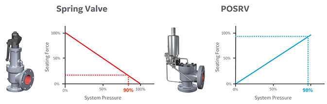
Your pressure safety valve is a direct spring-loaded pressure-relief valve that is opened by the static pressure upstream of the valve and characterized by rapid opening or pop action.
When the static inlet pressure reaches the set pressure, it will increase the pressure upstream of the disk and overcome the spring force on the disk.
Your construction code for pressure safety valve is API Standard 526 and covers the minimum requirements for design, materials, fabrication, inspection, testing, and commissioning.
These are:API Recommended Practice 520 for Sizing and SelectionAPI Recommended practice 521 Guideline for Pressure Relieving and Depressing SystemsAPI Recommended Practice 527 Seat Tightness of Pressure Relief Valves
For example in the state of Minnesota the ASME Code application and stamping for pressure vessel and boiler is mandatory which “U” and “S” symbols are designated for stamping on the nameplate.
For example if there is pressure vessel need to be installed in the state of Minnesota then the pressure vessel nameplate shall be U stamped and pressure vessel safety valve shall be UV stamped.
National Board Inspection Code (NBIC) have own certification scheme for pressure safety valves and using NB symbol. The NBIC code book for this certification is NB 18.
National Board Inspection Code is assisting ASME organization for ASME UV symbol certification by providing ASME designee in manufactures auditing program.
There are some other standards and codes which are used in pressure safety valve such as:ASME PTC 25 for pressure relief devices which majorly is used for assessment of testing facility and apparatus for safety valvesBS EN ISO 4126-1, 4126-2 and 4126-3 which is construction standard similar to API STD 526.
This API RP 527 might be used in conjunction of API RP 576 as testing procedure for seat tightness testing of pressure safety valve for periodical servicing and inspection.
These are only important points or summery of points for pressure safety valve in-service inspection and should not be assumed as pressure safety valve inspection procedure.
Pressure safety valve inspection procedure is comprehensive document which need to cover inspection methods to be employed, equipment and material to be used, qualification of inspection personnel involved and the sequence of the inspection activities as minimum.
You may use following content as summery of points for Pressure Safety Valve Inspection in operational plantDetermination pressure safety valve inspection interval based API STD 510 and API RP 576 requirementsInspection of inlet and outlet piping after pressure safety valve removal for any foulingInspection of pressure safety valve charge and discharge nozzles for possible deposit and corrosion productsTaking care for proper handling of pressure safety valves from unit to the valve shop. The detail of handling and transportation instruction is provided in API RP 576.Controlling of seals for being intact when the valves arrived to the valve shop.Making as received POP test and recording the relieving pressure.
If the POP pressure is higher than the set pressure the test need to be repeated and if in the second effort it was near to the set pressure it is because of deposit.If in the second effort it was not opened near to the set pressure either it was set wrongly or it was changed during the operationIf the pressure safety valve was not opened in 150% of set pressure it should be considered as stuck shut.If the pressure safety valve was opened below the set pressure the spring is weakenedMaking external visual inspection on pressure safety valve after POP test. The test need contain following item as minimum;the flanges for pitting and roughness
Making body wall thickness measurementDismantling of pressure safety valve if the result of as received POP test was not satisfactoryMaking detail and comprehensive visual and dimensional inspection on the dismantled valve parts (after cleaning)Making special attention to the dismantled valves seating surfaces inspection e.g. disk and seat for roughness, wear and damage which might cause valve leakage in serviceReplacing the damaged parts in dismantled valves based manufacture recommendation and API RP 576 requirementsMaking precise setting of the pressure safety valve after reassembly based manufacture recommendation or NB-18 requirements
Making at least two POP test after setting and making sure the deviation from set pressure is not more than 2 psi for valves with set pressure equal or less than 70 psi or 3% for valves with set pressure higher than 70 psiMaking valve tightness test for leakage purpose after approval of the setting pressure and POP tests. The test method and acceptance criteria must be according to the API RP 576.The API RP 527 also can be used for pressure safety valve tightness test.Recording and maintaining the inspection and testing results.

Boiler explosions have been responsible for widespread damage to companies throughout the years, and that’s why today’s boilers are equipped with safety valves and/or relief valves. Boiler safety valves are designed to prevent excess pressure, which is usually responsible for those devastating explosions. That said, to ensure that boiler safety valves are working properly and providing adequate protection, they must meet regulatory specifications and require ongoing maintenance and periodic testing. Without these precautions, malfunctioning safety valves may fail, resulting in potentially disastrous consequences.
Boiler safety valves are activated by upstream pressure. If the pressure exceeds a defined threshold, the valve activates and automatically releases pressure. Typically used for gas or vapor service, boiler safety valves pop fully open once a pressure threshold is reached and remain open until the boiler pressure reaches a pre-defined, safe lower pressure.
Boiler relief valves serve the same purpose – automatically lowering boiler pressure – but they function a bit differently than safety valves. A relief valve doesn’t open fully when pressure exceeds a defined threshold; instead, it opens gradually when the pressure threshold is exceeded and closes gradually until the lower, safe threshold is reached. Boiler relief valves are typically used for liquid service.
There are also devices known as “safety relief valves” which have the characteristics of both types discussed above. Safety relief valves can be used for either liquid or gas or vapor service.
Nameplates must be fastened securely and permanently to the safety valve and remain readable throughout the lifespan of the valve, so durability is key.
The National Board of Boiler and Pressure Vessel Inspectors offers guidance and recommendations on boiler and pressure vessel safety rules and regulations. However, most individual states set forth their own rules and regulations, and while they may be similar across states, it’s important to ensure that your boiler safety valves meet all state and local regulatory requirements.
The National Board published NB-131, Recommended Boiler and Pressure Vessel Safety Legislation, and NB-132, Recommended Administrative Boiler and Pressure Vessel Safety Rules and Regulationsin order to provide guidance and encourage the development of crucial safety laws in jurisdictions that currently have no laws in place for the “proper construction, installation, inspection, operation, maintenance, alterations, and repairs” necessary to protect workers and the public from dangerous boiler and pressure vessel explosions that may occur without these safeguards in place.
The documents are meant to be used as a guide for developing local laws and regulations and also may be used to update a jurisdiction’s existing requirements. As such, they’re intended to be modifiable to meet any jurisdiction’s local conditions.
The American Society of Mechanical Engineers (ASME) governs the code that establishes guidelines and requirements for safety valves. Note that it’s up to plant personnel to familiarize themselves with the requirements and understand which parts of the code apply to specific parts of the plant’s steam systems.
High steam capacity requirements, physical or economic constraints may make the use of a single safety valve impossible. In these cases, using multiple safety valves on the same system is considered an acceptable practice, provided that proper sizing and installation requirements are met – including an appropriately sized vent pipe that accounts for the total steam venting capacity of all valves when open at the same time.
The lowest rating (MAWP or maximum allowable working pressure) should always be used among all safety devices within a system, including boilers, pressure vessels, and equipment piping systems, to determine the safety valve set pressure.
General guidance on proper installation may seem like common sense to experienced installers and inspectors. A few of the most important guidelines and best practices include:
Avoid isolating safety valves from the system, such as by installing intervening shut-off valves located between the steam component or system and the inlet.
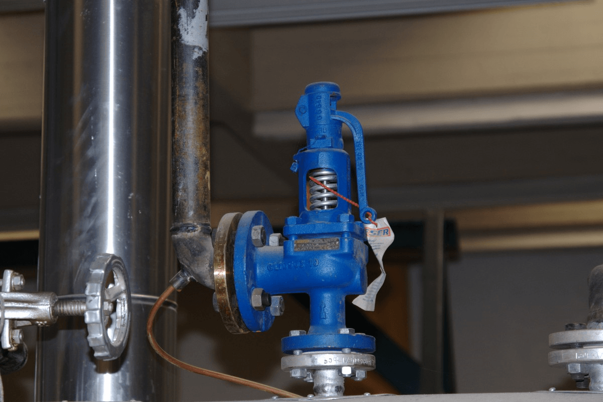
Contact the valve supplier immediately for any safety valve with a broken wire seal, as this indicates that the valve is unsafe for use. Safety valves are sealed and certified in order to prevent tampering that can prevent proper function.
Avoid attaching vent discharge piping directly to a safety valve, which may place unnecessary weight and additional stress on the valve, altering the set pressure.
Safety valves are required by code and insurers. Therefore, it is important to have good, up-to-date records of all safety valves in the steam system. With today’s readily available technology, a database should be developed containing all the relative information of all safety devices in a facility. The safety valve database should be reviewed on a periodic basis depending on plant standards, insurance company recommendations and the local, state or federal government requirements.
The code that establishes the requirements for safety valves is governed by the American Society of Mechanical Engineers (ASME). Through its committees, ASME has published and continues to update the Boiler and Pressure Vessel codes for safety valves. It is the responsibility of plant personnel, primarily the steam team, to know which codes apply to the different parts of the steam system.
In the United States, the major considerations for safety valves are proper sizing, followed by correct installation. A partial listing of sizing and installation highlights is listed below.
• When considering a safety valve downstream of a steam pressure control valve, the total capacity of the safety valve at the set point must exceed the steam control valve’s maximum flow capacity (largest orifice available) if the steam valve were to fail open. The inlet steam pressure to the valve must be calculated at the maximum safety valve setting of the steam supply source, not the nominal operating pressure. It is important not to oversize a safety valve. Bigger is not better in this case because a larger than required valve could cause chatter, leakage and premature failure.
• Many times, a single safety valve is not possible due to high capacity, physical limitations or economic considerations. An acceptable alternative method is to employ multiple safety valves on the same system. The valves should be of the same set point and the capacities must be equal to or greater than the rating of the equipment. Additionally, the vent pipe must be sized to account for the venting capacity of all the safety valves fully opening at the same time
• The set pressure of the safety valve shall be set at or below the Maximum Allowable Working Pressure (MAWP) of the component with the lowest set point in the system. This includes but is not limited to steam boilers, pressure vessels and equipment, and piping systems. In other words, if two components on the same system are rated at different pressures, the safety device protecting both of these devices must be set at the lower of the two ratings.
• There shall be no intervening shut-off valves located between the safety valve inlet and the steam component that could permit the safety valve to be isolated from the system
• Safety valves are set, sealed and certified to prevent tampering. If the wire seal is broken, the valve is unsafe and should not be used. Contact the supplier immediately
• For multiple safety valve installations using a single connection, the internal cross-sectional area of the inlet shall be equal to the combined inlet areas of all the safety valves
• All safety valves should use a drip pan elbow on the outlet. The drip pan elbow changes the outlet of the safety device from horizontal to vertical. Install the drip pan according to manufacturer guidelines
• The discharge outlet of the vent pipe should be piped to the closest location where free discharge of the safety device will not pose a safety hazard to personnel. For a roof line termination, the vent should be no less than 7ft above roof line. The top of the vent line should be cut at a 45-degree angle to dissipate the discharge thrust of the steam, prevent capping of the pipe, and to visually signify that it is a safety valve vent line.
The proper selection, installation and use of safety valves requires a complete understanding of ASME code and any additional requirements adopted by insurance companies or the local jurisdictional authority.
Kelly Paffel is a recognized authority in steam and condensate systems. He is a frequent lecturer and instructor on the technical aspects of steam systems. In addition, Kelly has published many papers on the topics of steam system design and operation. Over the past 30 years, he has conducted thousands of steam system audits and training sessions in the United States and overseas, which has made Kelly an expert in trouble-shooting actual and potential problems in the utilities of steam. Kelly is a member of the U.S. Department of Energy’s (DOE) Steam Best Practices and Steam Training Committees.

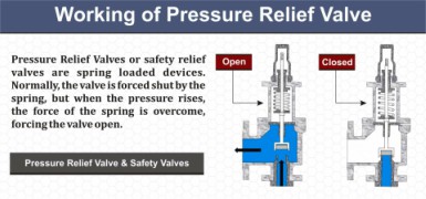
Pressure relief valves—also known as pressure release valves—open at predefined pressure threshold to release fluid or air until the internal pressure of the system returns to tolerable levels. These valves are essential in many processes to ensure that a pressure overload doesn’t break seals or cause an explosion.
Pressure relief valves facilitate pressure regulation in a broad range of process systems and equipment used for a variety of gases and liquids, such as:
Type of fluid/gas.An effective safety valve must be able to contain and control fluid/gas flow and release. Manufacturers and users must ensure that the correct body type and seal material are utilized for the intended application.
Size and weight.Many applications require valve components that can fit into tight spaces. The valve material, mounting options, and thread sizes will also impact its weight.
Materials.Common valve materials include brass, aluminum, plastic, and stainless steel. Each material has its own unique benefits, drawbacks, and material compatibilities.
Temperature.The source material for a valve component must be aligned with the expected operating temperature of the application. Temperature level can affect the functionality of the valve spring, as well as flow capacity.
Pressure limits and specifications for valves that must hold more than 15 psi of pressure are codified in the ASME Boiler and Pressure Vessel Code. Diaphragm-based designs and piston-based designs typically offer different thresholds for maximum source pressure and relief pressure ranges.
When considering a new installation, upgrade, or repair, it’s important to consult with a professional that has experience with pressure relief valves. An expert can help you perform a cost-benefit analysis to make the best decision for your current and projected needs.
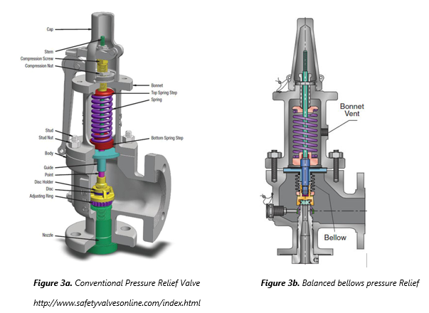
Spring-loaded pressure relief valves.This is the more basic of the two pressure release valve designs. It involves a spring-loaded mechanism that will compress when the system’s internal pressure reaches a preset threshold, thus opening up the release valve for discharge. The spring can be adjusted to collapse under a lower or higher amount of pressure. Most spring loaded designs have a secondary control chamber to enhance the mechanism’s lift.
Balanced bellows/balanced piston valves.Balanced bellows and balanced piston designs incorporate an advanced spring-loaded action that minimizes the effect of back pressure on set pressure. This design category is recommended for applications that operate within a variable back pressure environment.
Set pressure.A valve’s set pressure for release should not be higher than the maximum allowable working pressure of the boiler or vessel. Failure to comply with this requirement could lead to a pressure explosion.
Service.Consider the process flow—steam, air, gas, corrosive or non-corrosive, toxic, flammable—to ensure you select an appropriate material that can tolerate any negative effects.
Required capacity.This consideration is determined by factors such as valve geometry, operating temperature, and relief discharge area. It can be expressed in pounds per hour for steam flow, standard cubic feet per minute for air or gas flow, or gallons per minute for liquid flow.
Airtrol Components, Inc. has been a family-owned and operated provider of precision miniature pneumatic components since 1977. Our experienced engineers can help you determine the necessary components for your application type. For more information about our pressure relief valves or other products, pleasecontact ustoday.
Pressure relief valves are used to protect equipment from excessive overpressure. Properly sized relief valves will provide the required protection, while also avoiding issues with excessive flow rates, including: possible valve damage, impaired performance, undersized discharge piping and effluent handling systems, and higher costs.
Many scenarios can result in an increased vessel pressure, and each scenario may result in a different valve size. It is generally recommended to perform multiple case studies to find the most conservative sizing. Some typical cases include:
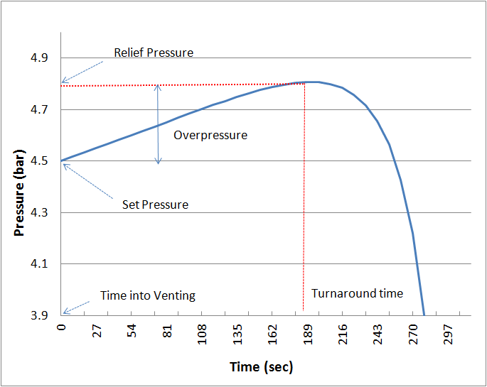
In any of these scenarios, the pressure will increase until a predetermined relief pressure is reached, at which point the relief pressure valve will open, decreasing the pressure after the turnaround time. The first step in sizing a Relief Valve in ProMax is to determine which scenario you are interested in modeling.
The Relief Valve Sizing in ProMax is performed as a stream analysis. Any stream in ProMax may have one or more Relief Valve Sizing Analyses added, so multiple cases can be studied in a single stream if desired.
There are many different standards for Relief Valve Sizing, each applying different assumptions, thus giving different results. For instance, API 520, one of the most cited standards, assumes both a mechanical and thermodynamic equilibrium, and constant phase properties during relief. Alternatively, the EN ISA 4126 standard accounts for thermodynamic non-equilibrium. ProMax currently supports six different sets of Relief Valve Sizing Standards:
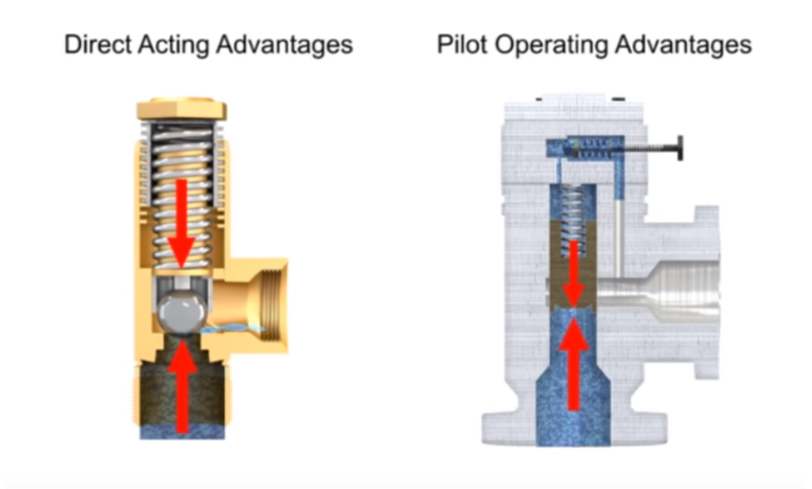
Next, an appropriate relief type must be selected, as sizing depends on the type of relief device selected. The operation of conventional spring-loaded pressure relief valve is based on a force balance: the spring-load is preset to apply a force opposite in amount to the pressure force exerted by the fluid on the other side when it is at the set pressure. When the fluid pressure exceeds the set pressure, the pressure force overcomes the spring force, and the valve opens. Any back pressure (downstream pressure) is additive to the spring force; if this back pressure varies, then the pressure at which the valve opens will vary. Bellows are used to maintain a constant relief pressure despite back pressure variations. Rupture disc relief valves do not reclose after activation; preference should usually be given to reclosing relief devices for both safety and reliability. The most common valve types include:
Balanced Bellows- spring loaded pressure relief valve that incorporates a bellows for minimizing the effect of back pressure on the operational characteristics of the valve.
Pilot Operated- a pressure relief valve in which the major relieving device or main valve is combined with and controlled by a self-actuated auxiliary pressure relief valve (pilot).
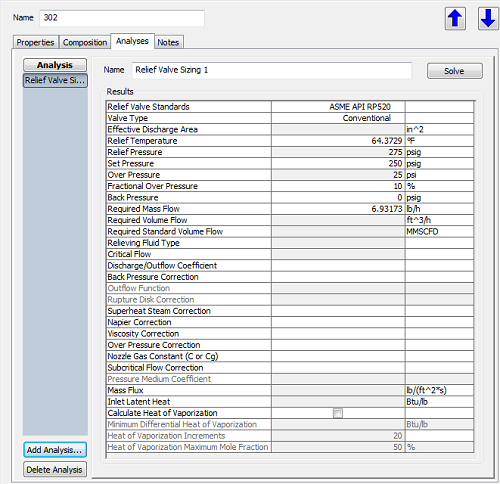
The Relief Temperature is determined by which pressure relief scenario you have chosen to model, and should be the temperature of the fluid at the time that the valve is expected to open. ProMax assumes that the Relief Temperature will be the current stream temperature, however, if your particular scenario requires that this be adjusted, it can be overwritten directly in the analysis dialog.
The Relief Pressure is generally determined by the equipment being protected, and is calculated as Relief Pressure = Set Pressure + Overpressure. By default, ProMax uses the stream pressure as the Set Pressure, and a 10% Over Pressure, but these can be modified for your analysis.
A relief device’s maximum allowable Set Pressure is equal to the vessel’s Maximum Allowable Working Pressure (MAWP) for vessels protected by a single relief device. The MAWP is set according to a specific temperature, the Maximum Allowable Working Temperature (MAWT). As the MAWT increases, the MAWP decreases because of the reduction in strength of metal at higher temperatures.
However, relief devices are typically set to open at the design pressure, instead. In some cases, the design pressure is equal to the MAWP – but it will never exceed it. In cases where the MAWP is not well-established, the design pressure may be used for the set pressure.
The Set Pressure is usually given in terms of gauge pressure, therefore any Back Pressure is added to the set pressure and overpressure to calculate the Relief Pressure in absolute units. The Back Pressure includes both the constant superimposed downstream pressure and any built-up backpressure due to the discharge of the fluid from the relief device through the downstream piping and treatment system.
The Over Pressure is usually expressed as a percentage of the Set Pressure. For spring-operated relief valves, a small amount of leakage occurs at 92-95% of theSet Pressure, and sufficient Over Pressure is necessary to achieve full lift. ASME-certified relief valves are required to reach full-rated capacity at 10% or less overpressure.
Note: A similar term, the Pressure Accumulation, is based on the MAWP instead of the Set Pressure. In cases where the Set Pressure is equal to the MAWP, then the overpressure and pressure accumulation are the same. The allowable accumulation for pressure vessels protected by a single relief device is 110% of the MAWP, except in fire exposure scenarios where 121% is allowed. When multiple relief devices are used for non-fire scenarios, the allowable accumulation is 116%.
The default value for this parameter is the mass flow of the stream in the simulation, but it can be set to the desired value for a specific scenario.
Once you’ve determined your emergency scenario, and specified the relieving conditions and flowrate, and the appropriate standard, ProMax will calculate the Effective Discharge Area. This value is used to select the appropriately sized Pressure Relief Valve.
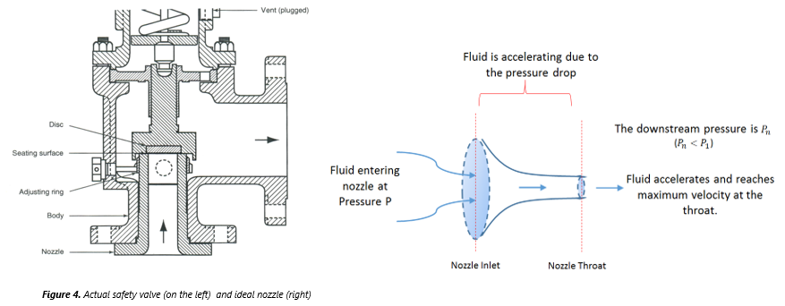
Although an orifice is often used to describe the minimum flow area constricted in the valve, the geometry and relief area calculations are more appropriately modeled based on an ideal (isentropic) nozzle. The expression for the mass flux (Gn) in an ideal nozzle is obtained directly from Bernoulli’s equation in the nozzle:
In this equation, un is the fluid velocity at the nozzle throat, An is the throat area, and p, u, and A are the density, velocity, and flow area, respectively,
at any given point in the nozzle. The fluid density decreases as it flows through the nozzle due to the decrease in pressure. Additionally, the flow area decreases as the nozzle restricts, reaching a minimum value of An
at the throat. The velocity u, then must increase, and reaches un at the throat. The rate of increase in velocity is greater than the rate of decrease in density, therefore the mass flux reaches a maximum at the throat.
Single and two-phase flows are both frequently encountered in various relief scenarios. Due to the large number of variables associated with the fluid properties,
distribution of fluid phases, interaction, and transformation of the phases, sizing a two-phase relief scenario is considerably more complex than single-phase. The Mass Flux calculation varies depending on the relieving fluid type:
This equation is valid for fully turbulent flow, where the flowrate is independent of the fluid viscosity. For low Reynolds number (high-viscosity) flows, values can be multiplied by a correction factor.
For a vapor flow, the equation used depends on whether the flow rate is critical or subcritical. When the downstream pressure is reduced, the velocity and mass flux increase at the throat; eventually the mass flux
reaches a maximum value at the choked, or critical, flow pressure. Subcritical flow is a function of both upstream and downstream pressures, whereas choked flow is a function of only the inlet conditions.
Frozen flow occurs if the vessel initially contains both gas and nonvolatile liquid (for instance a vessel with an inert-gas padding), hence it flows at a constant quality
This type of flow is often encountered at metering devices in chemical processing and in relief valve sizing applications where both non-condensable and condensable (flashing) components
This assumes that the two phases are flowing at the same velocity, with no slip between the phases. Although there are a variety of models in the literature for estimating the slip as a
function of fluid properties and flow conditions, it is often neglected under pressure-relief conditions because of the high degree of turbulence and mixing.
It is commonly assumed that the gas or vapor phase is in local thermodynamic equilibrium with the liquid phase, meaning the properties of the mixture are a function of only the local
temperature, pressure, and composition. When the pressure drops to the saturation pressure of the liquid, flashing occurs instantly if thermodynamic equilibrium is assumed. However, flashing
This term is an estimation used in sizing pressure relief valves for two-phase liquid/vapor applications when the system has less than 0.1 wt% H2, a nominal boiling range less than 150°F, and
is far from the critical point. It’s important to note that true “Latent Heat” is a pure component property, and extending the definition to a multi-component mixture requires making assumptions.
As such, there are multiple methods of approximating the latent heat, and the Relief Valve Sizing analysis follows the methodology of the standards. For example, the API 520 standard defines “latent heat” as
the difference between the vapor and liquid specific enthalpies at the inlet temperature and bubble point pressure for sub-cooled liquids, and at the inlet temperature and inlet pressure for a two-phase flashing flow.
The Heat of Vaporization calculation is an alternative to the Latent Heat calculation utilizing a batch distillation approach. This calculation generates pseudo instantaneous Heat of Vaporization
values for cumulative amounts of vapor boiled off from the system. Values are generated for the specified number of Heat of Vaporization Increments from 0% up to the specified Heat of Vaporization
Darby, R., Meiller, P. R., Stockton, J. R. (2001). Select the Best Model for Two-Phase Relief Sizing, Chemical Engineering Progress, Vol.97, No.5, pp 56.
You may not worry often, if at all, about whether or not your air compressor is running safely. And you really don’t have to, because compressor manufacturers do. From the pressure rating on the air storage tank to emergency stop buttons, air compressors are designed with safety in mind.
But that doesn’t mean you should never think about your compressor’s safety features. In most cases, they need to be inspected regularly to make sure they’re working properly. One key safety feature that should be inspected regularly is the air pressure relief valve (PRV), sometimes called a safety relief valve.
The pressure relief valve is a safety valve that protects the compressor component that it’s attached to from being exposed to a pressure above its rated maximum operating pressure. This rating, called the maximum working pressure (MWP), is the pressure that the vessel has been certified to continuously operate at safely.
So when a compressor is running at or below its maximum working pressure—in other words, when it’s running “normally”—the relief valve doesn’t do anything.
However, when the air pressure inside a compressor exceeds its MWP, the pressure relief valve will activate to “blow off” the excessive pressure within the compressor. Without a relief valve, the storage tank could rupture from the excessive pressure, damaging the compressor itself, possibly other property near it, and even causing injuries (or worse) to anyone standing nearby.
Before we can talk about how the air pressure relief valve works, we first need to look at how air pressure inside a compressor is managed when everything is running normally.
Under normal circumstances, the air pressure in a compressor is controlled by a pressure switch in an electro/mechanical control system or, in the case of an electronic controller, a pressure transducer and controller settings. When the cut-out set pressure for the pressure switch is reached, the compressor will stop compressing air (unload) until the cut-in set pressure is reached, at which time it will start compressing air again (load). If the pressure switch fails, the compressor would not be able to start compressing air again, or potentially worse, not be able to stop. Most compressors also have a high-pressure safety switch that should stop the compressor if the pressure exceeds the unload set point.
A pressure relief valve is a straightforward safety backup to the pressure switch and high-pressure switch, or the controller set points, should any of these components fail with the compressor running. The safety relief valve is set above the high-pressure safety switch and generally at or below the vessel’s maximum operating pressure. Inside the valve is a spring, and the pressure created by the spring’s tension keeps the valve closed under normal operating conditions. However, as the air pressure increases in pressure vessels (like the storage tank), it eventually exceeds the rated pressure of the relief valve, causing the relief valve to open and the excess pressure to be “blown off” to the atmosphere.
If the pressure relief valve fails open, air will continually vent to the atmosphere, preventing the air stream from becoming fully pressurized. The compressor should be shut down and the relief valve replaced before the compressor is restarted. The open relief valve will likely cause a loss of production and possible danger to personnel as a result of the flow of high-pressure air with flying debris and an unsafe sound level.
A pressure relief valve failing closed presents a potentially more dangerous situation. As noted earlier, the relief valve exists to allow excessive pressure to be “blown off” so that the air pressure inside the compressor’s pressure vessels don’t exceed their rated specifications. If the valve fails closed, this pressure venting can’t happen. Unless compressed air demand matches the compressed air supply, the pressure inside the compressor will continue to build. Eventually, the pressure increase would cause the storage tank to rupture, damaging the compressor and possibly causing additional damage and injury to property and people nearby.
If the relief valve is opening because the air pressure in the compressor has exceeded the valve’s pressure set point, that means the valve is working and doing what it was designed to do. But because this indicates the MWP of the compressor has been exceeded, the condition that’s causing excessive pressure should be diagnosed and corrected.
If the relief valve opening wasn’t caused by excessive pressure inside the compressor, then the valve is most likely “failing open”. Most likely, this is because the valve has become “soft” over time, i.e. the valve spring is providing less counterpressure, so it’s opening at a lower pressure than it should.
Whether the valve opened because of excessive pressure in the compressor or because the valve is failing, you should have your local air compressor distributor inspect your compressor before running it again for two reasons:
First, your distributor can determine whether the valve opened due to a failing relief valve or excessive compressors pressure and perform any needed maintenance or service to get your compressor running efficiently and safely again.
Second, regardless of why the pressure relief valve opened, replacing it may be recommended to ensure safe compressor operation, depending on the valve manufacturer. (Replacement is recommended for Sullair compressors.)
Important: Running the compressor after the relief valve has opened, regardless of the reason why it opened, can put both your property at risk of damage and people at risk of injury (or worse). While this may be obvious if the compressor is building up excess pressure, it also applies if the valve failed open. As noted above, even a valve that fails open poses some risk, and next time it could fail closed.
Given how critical a working air pressure relief valve is to the safe and efficient operation of your air compressor, you may wonder whether you need to do any regular inspecting or testing of the valve to make sure it is working. Because this can vary by manufacturer, you should consult your owner’s manual or contact your local air compressor distributor for frequency and type of inspection needed. For most Sullair compressors, inspection for damage or leakage is recommended, but testing is not recommended, as doing so may compromise the valve’s performance.
However, one thing you should do is schedule regular maintenance with your local air compressor distributor. As part of regular maintenance, a service technician can inspect the PRV and let you know it’s at an age or in a condition at which the manufacturer recommends replacement. Also, problems with the compressor’s performance, e.g. not reaching normal operating pressure, may help the service technician identify a failing relief valve after ruling out other possible causes.
When a pressure vessel like a receiver, sump tank or other storage vessel is purchased separately from the compressor, it may not be supplied with a pressure relief valve. To ensure its safe operation, you should add a PRV.
When selecting a PRV to add to the pressure vessel, you must choose a valve with a pressure set point set at or below the maximum working pressure of the vessel. You will find the MWP (and other useful information) on a tag welded to the pressure vessel. Also, flow capacity of the PRV must meet or exceed the total compressed air supplied to the vessel.
For example, if you have two compressors with capacities of 500 and 750 cfm (14.2 and 21.2 m³/min), and a pressure vessel with a maximum working pressure of 200 psi (13.8 bar), the minimum settings for a pressure relief valve would be 1250 cfm (35.4 m³/min) and a set point 200 psi (13.8 bar) or less.
Finally, when attaching the valve to the vessel, the porting must not be reduced to a size less than the size of the inlet port of the pressure relief valve.
Because the pressure relief valve is critical to the safe operation of your compressed air system, if you’re not sure how to select the correct PRV and properly and safely add it to the pressure vessel, contact your local air compressor distributor. They have the experience and expertise to ensure that the PRV is sized and installed correctly.

One of the simplest but most important instruments that I encounter which are used not for displaying or monitoring the process, but for safety, is the pressure safety valves.
When I was just starting out as a cal tech, looking at it installed in a tank makes me curious about its usage. You cannot see any actions or output display as a sign of its operation.
Pressure Safety Valve or safety valves as the name implies is a type of pressure relief valve used to protect pressure vessels from excessive pressure, characterized by a rapid opening or a pop action once it reached the set pressure.
PSV is used specifically on safety concern. It is simple in use but one of the very important parts of safety. Only powered by the fluid pressure to do its safety job, it does not use electrical power. This makes it the last line of protection when every other device fails.
When I was first exposed in this type of pressure instrument, I thought Pressure Safety Valves (PSV) is the same with Pressure Relief Valves or PRV, I did not know that they are different in some ways.
Every manufactured PSV has a set pressure engraved on its body. A set pressure that we need to verify to ensure that the valve will perform its function when needed.
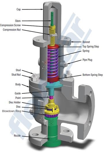
A PSV is purely mechanical, it has a strong spring inside that is perfectly designed to give the required set pressure. One of these mechanical parts (like the disc) can wear which can affect the set pressure.
Exposure to contaminants like dust or debris coming out with the fluid can affect the resealing or closing of the disc after release that may result in a leak.
Sometimes, the closed position of PSV disc where it did not open or activated for a longer period has the tendency to stick (stuck-up). This affects the set pressure. Thus, it is a good way to exercise the valve.
PSV calibration is done by comparing the set pressure, which is the rapid releasing action (popping) of the PSV, to the displayed value of the reference standard. The pressure relief valve testing procedure to verify the accuracy of output pressure (set pressure) is the same.
If you want to know other types of valve testing to determine its full performance like leak testing and flow characteristics, you may need to refer to ISO 4126-1.
Determine the set point of the pressure gauge. Be aware of this set point to anticipate the opening of the valve while controlling the pressure source.
PSV calibration frequency is based on the performance of your safety valves. A 1-year interval is ok as per my experience but I also see PSV calibration interval up to 3 years. As I said, it depends on how it performed based on its history. As an initial interval, start to 1 year then increase it based on its performance. How to implement this? Visit my other post in this link >> calibration frequency
Because of the rapid popping action during the discharge, it is hard to notice the difference of set pressure and overpressure. Without the tolerance specified, set pressure and overpressure reading are the same, mostly for results higher than set pressure.
We are using a 10% tolerance or the tolerance specified by the manufacturer or as per the requirement of the user as the basis for a pass or failed verification.
PSV has a set pressured that is determined by the strength of the spring inside it. The more the spring it is compressed, the stronger or higher the pressure it can withstand or create.
In order to adjust the set pressure, we need to change the compression and/or the elongation of the spring by rotating the adjusting screw located just above the spring.
Pressure safety valve or PSV is the last line of protection for all pressured vessel or tanks from over pressure using only the system pressure as the source of power. In this post, I have presented what is a safety valve, Its difference with a relief valve, why do we need to calibrate a Pressure Safety Valve, PSV Calibration Setup and procedure, The 3 stages to observe during calibration,how to verify a safety valve and how to adjust a safety valve inlcuding the main parts of a PSV.

This website is using a security service to protect itself from online attacks. The action you just performed triggered the security solution. There are several actions that could trigger this block including submitting a certain word or phrase, a SQL command or malformed data.

Relief and safety Valves are used in high pressure systems to control the pressure and keep balance of the system. The different between safety valves and relief valves is that the safety valves fully open or close under a certain pressure while the relief valves can open in proportion to the pressure in front of them. The safety and pressure relief valves are used automatically. They both operate under similar conditions. When the pressure builds up in a system, it has to be managed by releasing the material to flow through. These valves have a threshold pressure at which they open. The consolidated safety and safety relief valves comprise of a bonnet vent and bellow with springs.
The springs are set up for the threshold pressure and when the pressure exceeds the threshold, the spring is pushed into the bonnet vent and the bellow opens the valve. The Safety Relief Valves can be open and shut valves. They either open or shut off at any given pressure. This is mostly for the safety of an application not to explode under high pressure. The Pressure Relief Valve on the other hand releases the material after the threshold pressure, but not fully. If the pressure is slightly higher the threshold, then the valve opens slightly. If the pressure is very high above the threshold, it opens wider. It also functions in the same manner when the pressure drops down. The valve closes in proportion to the pressure. The safety valve shuts down at once only when the pressure is below the threshold.
Ready Stock of ASTM A351 CF8M Spring Loaded Safety Valve in wide range of Sizes, Stainless Steel Air Compressor Pressure Relief Valve Manufacturers In India
Relief Valves are designed to control pressure in a system While Safety Valves are used for controlling the pressure in a system they release pressure immediately in the event of an emergency or system failure
The Setpoint of relief valve is usually set at 10 Percent above working pressure limit while safety valve is usually set at 3% above working pressure limit.
If you are operating systems that can only be off for short periods of time, it is sensible to keep a spare valve to swap over and then the removed valve can be inspected and recertified.
This website is using a security service to protect itself from online attacks. The action you just performed triggered the security solution. There are several actions that could trigger this block including submitting a certain word or phrase, a SQL command or malformed data.
This website is using a security service to protect itself from online attacks. The action you just performed triggered the security solution. There are several actions that could trigger this block including submitting a certain word or phrase, a SQL command or malformed data.

Safety relief valves are designed to performance standards. They are configured to open to their maximum rated flow capacity and stay open. Proportional relief valves open in response to increasing upstream pressure and produce variable flow rates in direct relationship to the upstream pressure. They reduce flow and will re-seat with reduction in upstream pressure.
Proportional relief valve are not intended to be used as safety relief valves but as safety accessories intended to reduce spike pressures on instrumentation equipment, rather than being a primary system relief valve.
Unfortunately we do not have any such information for calculation other than the guide information in the catalog, See catalog page 3 (4190-HPRV). Valves which are not actuated for a period of time may initially crack at higher than set pressures.
The HPRV Series Relief Valves are set and wire locked in factory in order to achieve PED certification and for that reason they are not a serviceable/ maintainable part due to the fact that as soon as the wire lock is broken or removed the valve is no longer PED certified. As a result instructions are not available.
We can provide C3 option(cleaned for oxygen service) on the relief valves. Customer will need to make the determination if the valve will work in their application
Safety valves are an arrangement or mechanism to release a substance from the concerned system in the event of pressure or temperature exceeding a particular preset limit. The systems in the context may be boilers, steam boilers, pressure vessels or other related systems. As per the mechanical arrangement, this one get fitted into the bigger picture (part of the bigger arrangement) called as PSV or PRV that is pressure safety or pressure relief valves.
This type of safety mechanism was largely implemented to counter the problem of accidental explosion of steam boilers. Initiated in the working of a steam digester, there were many methodologies that were then accommodated during the phase of the industrial revolution. And since then this safety mechanism has come a long way and now accommodates various other aspects.
These aspects like applications, performance criteria, ranges, nation based standards (countries like United States, European Union, Japan, South Korea provide different standards) etc. manage to differentiate or categorize this safety valve segment. So, there can be many different ways in which these safety valves get differentiated but a common range of bifurcation is as follows:
The American Society of Mechanical Engineers (ASME) I tap is a type of safety valve which opens with respect to 3% and 4% of pressure (ASME code for pressure vessel applications) while ASME VIII valve opens at 10% over pressure and closes at 7%. Lift safety valves get further classified as low-lift and full lift. The flow control valves regulate the pressure or flow of a fluid whereas a balanced valve is used to minimize the effects induced by pressure on operating characteristics of the valve in context.
A power operated valve is a type of pressure relief valve is which an external power source is also used to relieve the pr


 8613371530291