
at what psi is the safety valve set to open price

Finding a quality driving school in can be a difficult and time consuming task. driving-schools.com comprehensive database of driving schools helps you pick one that’s right for you.

In an air brake system, the first tank that receives compressed air has a safety valve that releases air if the pressure gets too high. It is usually set to open at 150 psi. If the valve must open, there is a fault in the system that should be repaired by a mechanic.
In order to ensure that the maximum allowable accumulation pressure of any system or apparatus protected by a safety valve is never exceeded, careful consideration of the safety valve’s position in the system has to be made. As there is such a wide range of applications, there is no absolute rule as to where the valve should be positioned and therefore, every application needs to be treated separately.
A common steam application for a safety valve is to protect process equipment supplied from a pressure reducing station. Two possible arrangements are shown in Figure 9.3.3.
The safety valve can be fitted within the pressure reducing station itself, that is, before the downstream stop valve, as in Figure 9.3.3 (a), or further downstream, nearer the apparatus as in Figure 9.3.3 (b). Fitting the safety valve before the downstream stop valve has the following advantages:
• The safety valve can be tested in-line by shutting down the downstream stop valve without the chance of downstream apparatus being over pressurised, should the safety valve fail under test.
• When setting the PRV under no-load conditions, the operation of the safety valve can be observed, as this condition is most likely to cause ‘simmer’. If this should occur, the PRV pressure can be adjusted to below the safety valve reseat pressure.
• Any additional take-offs downstream are inherently protected. Only apparatus with a lower MAWP requires additional protection. This can have significant cost benefits.
Indeed, a separate safety valve may have to be fitted on the inlet to each downstream piece of apparatus, when the PRV supplies several such pieces of apparatus.
• If supplying one piece of apparatus, which has a MAWP pressure less than the PRV supply pressure, the apparatus must be fitted with a safety valve, preferably close-coupled to its steam inlet connection.
• If a PRV is supplying more than one apparatus and the MAWP of any item is less than the PRV supply pressure, either the PRV station must be fitted with a safety valve set at the lowest possible MAWP of the connected apparatus, or each item of affected apparatus must be fitted with a safety valve.
• The safety valve must be located so that the pressure cannot accumulate in the apparatus viaanother route, for example, from a separate steam line or a bypass line.
It could be argued that every installation deserves special consideration when it comes to safety, but the following applications and situations are a little unusual and worth considering:
• Fire - Any pressure vessel should be protected from overpressure in the event of fire. Although a safety valve mounted for operational protection may also offer protection under fire conditions,such cases require special consideration, which is beyond the scope of this text.
• Exothermic applications - These must be fitted with a safety valve close-coupled to the apparatus steam inlet or the body direct. No alternative applies.
• Safety valves used as warning devices - Sometimes, safety valves are fitted to systems as warning devices. They are not required to relieve fault loads but to warn of pressures increasing above normal working pressures for operational reasons only. In these instances, safety valves are set at the warning pressure and only need to be of minimum size. If there is any danger of systems fitted with such a safety valve exceeding their maximum allowable working pressure, they must be protected by additional safety valves in the usual way.
In order to illustrate the importance of the positioning of a safety valve, consider an automatic pump trap (see Block 14) used to remove condensate from a heating vessel. The automatic pump trap (APT), incorporates a mechanical type pump, which uses the motive force of steam to pump the condensate through the return system. The position of the safety valve will depend on the MAWP of the APT and its required motive inlet pressure.
This arrangement is suitable if the pump-trap motive pressure is less than 1.6 bar g (safety valve set pressure of 2 bar g less 0.3 bar blowdown and a 0.1 bar shut-off margin). Since the MAWP of both the APT and the vessel are greater than the safety valve set pressure, a single safety valve would provide suitable protection for the system.
However, if the pump-trap motive pressure had to be greater than 1.6 bar g, the APT supply would have to be taken from the high pressure side of the PRV, and reduced to a more appropriate pressure, but still less than the 4.5 bar g MAWP of the APT. The arrangement shown in Figure 9.3.5 would be suitable in this situation.
Here, two separate PRV stations are used each with its own safety valve. If the APT internals failed and steam at 4 bar g passed through the APT and into the vessel, safety valve ‘A’ would relieve this pressure and protect the vessel. Safety valve ‘B’ would not lift as the pressure in the APT is still acceptable and below its set pressure.
It should be noted that safety valve ‘A’ is positioned on the downstream side of the temperature control valve; this is done for both safety and operational reasons:
Operation - There is less chance of safety valve ‘A’ simmering during operation in this position,as the pressure is typically lower after the control valve than before it.
Also, note that if the MAWP of the pump-trap were greater than the pressure upstream of PRV ‘A’, it would be permissible to omit safety valve ‘B’ from the system, but safety valve ‘A’ must be sized to take into account the total fault flow through PRV ‘B’ as well as through PRV ‘A’.
A pharmaceutical factory has twelve jacketed pans on the same production floor, all rated with the same MAWP. Where would the safety valve be positioned?
One solution would be to install a safety valve on the inlet to each pan (Figure 9.3.6). In this instance, each safety valve would have to be sized to pass the entire load, in case the PRV failed open whilst the other eleven pans were shut down.
If additional apparatus with a lower MAWP than the pans (for example, a shell and tube heat exchanger) were to be included in the system, it would be necessary to fit an additional safety valve. This safety valve would be set to an appropriate lower set pressure and sized to pass the fault flow through the temperature control valve (see Figure 9.3.8).
The Model 7000 is a pressure relief valve specifically designed to relieve excess pressure caused by pressure surges or temperature changes in all wet fire sprinkler systems. Model 7000 pressure relief valves comply with NFPA 13 requirements stipulating that a pressure relief valve must be installed on all wet systems and downstream of all pressure-reducing valves. Model 7000s feature a bronze body, stainless steel spring, and flushing handle to remove debris. The Model 7000 can be purchased individually or as part of the TESTanDRAIN Kit with all necessary drainage piping and connections for use with all AGF TESTanDRAIN valves. Pressure relief valves can be installed on a TESTanDRAIN valve without removing the valve from the line or draining the system completely. The 7000 features a 1/2" MIPT inlet and FIPT outlet and is UL Listed and FM Approved. It is rated for 175 PSI Systems. Other Ratings Available: 205, and 250. Please specify PSI when ordering.
UL and FM standards for sprinkler system pressure relief valves require relief valves to operate within a range of their ratings. FM requires a relief valve to OPEN at a pressure no less than 85% of their rating and UL requires OPENING at a pressure no greater than 105% of their rating. Both standards require the relief valves to CLOSE within a percentage below OPEN. Choose the relief valve comparing static pressure to 90% of the relief valve"s rating to determine the estimated minimum OPENING and 80% of the relief valve"s rating for the approximate maximum CLOSING. The relief valve should be installed where it is easily accessible for maintenance. Care should be taken that the relief valve CANNOT be isolated from the system when the system is operational. A relief valve should NEVER have a shutoff valve or a plug downstream of its outlet.

Recommended for all cold water system installations - to protect against damage to piping and pressure tanks. PRV"s are set at 75 PSI or 100 PSI. PRV"s have a plus/minus 15% setting accuracy
Note: Merrill pressure relief valves may not reseat themselves after pressure relief. Manual disassembly and reseating of the valve may be required. Repeated opening of a pressure relief valve is beyond intended use and voids warranty
*Note: ALL PRV valves are field adjustable - by removing the cap and turning internal disk down to increase pressure. Field adjustment of valve voids warranty.
Warning: ALL PRV, SSPRV, and PRVNL valves must be set a minimum of 15 PSI above the typical high of the water system pressure, so valve chatter or rapid open and close will not occur. Valve chatter can cause the failure of the valve and voids warranty.
Pressure relief valves (safety relief valves) are designed to open at a preset pressure and discharge fluid until pressure drops to acceptable levels. The development of the safety relief valve has an interesting history.
Denis Papin is credited by many sources as the originator of the first pressure relief valve (circa 1679) to prevent overpressure of his steam powered “digester”. His pressure relief design consisted of a weight suspended on a lever arm. When the force of the steam pressure acting on the valve exceeded the force of the weight acting through the lever arm the valve opened. Designs requiring a higher relief pressure setting required a longer lever arm and/or larger weights. This simple system worked however more space was needed and it coud be easily tampered with leading to a possible overpressure and explosion. Another disadvantage was premature opening of the valve if the device was subjected to bouncing movement.
Direct-acting deadweight pressure relief valves: Later to avoid the disadvantages of the lever arrangement, direct-acting deadweight pressure relief valves were installed on early steam locomotives. In this design, weights were applied directly to the top of the valve mechanism. To keep the size of the weights in a reasonable range, the valve size was often undersized resulting in a smaller vent opening than required. Often an explosion would occur as the steam pressure rose faster than the vent could release excess pressure. Bouncing movements also prematurely released pressure.
Direct acting spring valves: Timothy Hackworth is believed to be the first to use direct acting spring valves (circa 1828) on his locomotive engine called the Royal George. Timothy utilized an accordion arrangement of leaf springs, which would later be replaced with coil springs, to apply force to the valve. The spring force could be fine tuned by adjusting the nuts retaining the leaf springs.
Refinements to the direct acting spring relief valve design continued in subsequent years in response to the widespread use of steam boilers to provide heat and to power locomotives, river boats, and pumps. Steam boilers are less common today but the safety relief valve continues to be a critical component, in systems with pressure vessels, to protect against damage or catastrophic failure.
Each application has its own unique requirements but before we get into the selection process, let’s have a look at the operating principles of a typical direct acting pressure relief valve.
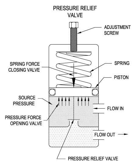
In operation, the pressure relief valve remains normally closed until pressures upstream reaches the desired set pressure. The valve will crack open when the set pressure is reached, and continue to open further, allowing more flow as over pressure increases. When upstream pressure falls a few psi below the set pressure, the valve will close again.
Most commonly, pressure relief valves employ a spring loaded “poppet” valve as a valve element. The poppet includes an elastomeric seal or, in some high pressure designs a thermoplastic seal, which is configured to make a seal on a valve seat. In operation, the spring and upstream pressure apply opposing forces on the valve. When the force of the upstream pressure exerts a greater force than the spring force, then the poppet moves away from the valve seat which allows fluid to pass through the outlet port. As the upstream pressure drops below the set point the valve then closes.
Piston style designs are often used when higher relief pressures are required, when ruggedness is a concern or when the relief pressure does not have to be held to a tight tolerance. Piston designs tend to be more sluggish, compared to diaphragm designs due to friction from the piston seal. In low pressure applications, or when high accuracy is required, the diaphragm style is preferred. Diaphragm relief valves employ a thin disc shaped element which is used to sense pressure changes. They are usually made of an elastomer, however, thin convoluted metal is used in special applications. Diaphragms essentially eliminate the friction inherent with piston style designs. Additionally, for a particular relief valve size, it is often possible to provide a greater sensing area with a diaphragm design than would be feasible with a piston style design.
The reference force element is usually a mechanical spring. This spring exerts a force on the sensing element and acts to close the valve. Many pressure relief valves are designed with an adjustment which allows the user to adjust the relief pressure set-point by changing the force exerted by the reference spring.
What is the maximum flow rate that the application requires? How much does the flow rate vary? Porting configuration and effective orifices are also important considerations.
The chemical properties of the fluid should be considered before determining the best materials for your application. Each fluid will have its own unique characteristics so care must be taken to select the appropriate body and seal materials that will come in contact with the fluid. The parts of the pressure relief valve in contact with the fluid are known as the “wetted” components. If the fluid is flammable or hazardous in nature the pressure relief valve must be capable of discharging it safely.
In many high technology applications space is limited and weight is a factor. Some manufactures specialize in miniature components and should be consulted. Material selection, particularly the relief valve body components, will impact weight. Also carefully consider the port (thread) sizes, adjustment styles, and mounting options as these will influence size and weight.
In many high technology applications space is limited and weight is a factor. Some manufactures specialize in miniature components and should be consulted. Material selection, particularly the relief valve body components, will impact weight. Also carefully consider the port (thread) sizes, adjustment styles, and mounting options as these will influence size and weight.
A wide range of materials are available to handle various fluids and operating environments. Common pressure relief valve component materials include brass, plastic, and aluminum. Various grades of stainless steel (such as 303, 304, and 316) are available too. Springs used inside the relief valve are typically made of music wire (carbon steel) or stainless steel.
Brass is suited to most common applications and is usually economical. Aluminum is often specified when weight is a consideration. Plastic is considered when low cost is of primarily concern or a throw away item is required. Stainless Steels are often chosen for use with corrosive fluids, when cleanliness of the fluid is a consideration or when the operating temperatures will be high.
Equally important is the compatibility of the seal material with the fluid and with the operating temperature range. Buna-N is a typical seal material. Optional seals are offered by some manufacturers and these include: Fluorocarbon, EPDM, Silicone, and Perfluoroelastomer.
The materials selected for the pressure relief valve not only need to be compatible with the fluid but also must be able to function properly at the expected operating temperature. The primary concern is whether or not the elastomer chosen will function properly throughout the expected temperature range. Additionally, the operating temperature may affect flow capacity and/or the spring rate in extreme applications.
Beswick Engineering manufactures four styles of pressure relief valves to best suit your application. The RVD and RVD8 are diaphragm based pressure relief valves which are suited to lower relief pressures. The RV2 and BPR valves are piston based designs.

Pressure relief valves are used to protect equipment from excessive overpressure. Properly sized relief valves will provide the required protection, while also avoiding issues with excessive flow rates, including: possible valve damage, impaired performance, undersized discharge piping and effluent handling systems, and higher costs.
Many scenarios can result in an increased vessel pressure, and each scenario may result in a different valve size. It is generally recommended to perform multiple case studies to find the most conservative sizing. Some typical cases include:
In any of these scenarios, the pressure will increase until a predetermined relief pressure is reached, at which point the relief pressure valve will open, decreasing the pressure after the turnaround time. The first step in sizing a Relief Valve in ProMax is to determine which scenario you are interested in modeling.
The Relief Valve Sizing in ProMax is performed as a stream analysis. Any stream in ProMax may have one or more Relief Valve Sizing Analyses added, so multiple cases can be studied in a single stream if desired.
There are many different standards for Relief Valve Sizing, each applying different assumptions, thus giving different results. For instance, API 520, one of the most cited standards, assumes both a mechanical and thermodynamic equilibrium, and constant phase properties during relief. Alternatively, the EN ISA 4126 standard accounts for thermodynamic non-equilibrium. ProMax currently supports six different sets of Relief Valve Sizing Standards:
Next, an appropriate relief type must be selected, as sizing depends on the type of relief device selected. The operation of conventional spring-loaded pressure relief valve is based on a force balance: the spring-load is preset to apply a force opposite in amount to the pressure force exerted by the fluid on the other side when it is at the set pressure. When the fluid pressure exceeds the set pressure, the pressure force overcomes the spring force, and the valve opens. Any back pressure (downstream pressure) is additive to the spring force; if this back pressure varies, then the pressure at which the valve opens will vary. Bellows are used to maintain a constant relief pressure despite back pressure variations. Rupture disc relief valves do not reclose after activation; preference should usually be given to reclosing relief devices for both safety and reliability. The most common valve types include:
Balanced Bellows- spring loaded pressure relief valve that incorporates a bellows for minimizing the effect of back pressure on the operational characteristics of the valve.
Pilot Operated- a pressure relief valve in which the major relieving device or main valve is combined with and controlled by a self-actuated auxiliary pressure relief valve (pilot).
The Relief Temperature is determined by which pressure relief scenario you have chosen to model, and should be the temperature of the fluid at the time that the valve is expected to open. ProMax assumes that the Relief Temperature will be the current stream temperature, however, if your particular scenario requires that this be adjusted, it can be overwritten directly in the analysis dialog.
The Relief Pressure is generally determined by the equipment being protected, and is calculated as Relief Pressure = Set Pressure + Overpressure. By default, ProMax uses the stream pressure as the Set Pressure, and a 10% Over Pressure, but these can be modified for your analysis.
A relief device’s maximum allowable Set Pressure is equal to the vessel’s Maximum Allowable Working Pressure (MAWP) for vessels protected by a single relief device. The MAWP is set according to a specific temperature, the Maximum Allowable Working Temperature (MAWT). As the MAWT increases, the MAWP decreases because of the reduction in strength of metal at higher temperatures.
However, relief devices are typically set to open at the design pressure, instead. In some cases, the design pressure is equal to the MAWP – but it will never exceed it. In cases where the MAWP is not well-established, the design pressure may be used for the set pressure.
The Set Pressure is usually given in terms of gauge pressure, therefore any Back Pressure is added to the set pressure and overpressure to calculate the Relief Pressure in absolute units. The Back Pressure includes both the constant superimposed downstream pressure and any built-up backpressure due to the discharge of the fluid from the relief device through the downstream piping and treatment system.
The Over Pressure is usually expressed as a percentage of the Set Pressure. For spring-operated relief valves, a small amount of leakage occurs at 92-95% of theSet Pressure, and sufficient Over Pressure is necessary to achieve full lift. ASME-certified relief valves are required to reach full-rated capacity at 10% or less overpressure.
Note: A similar term, the Pressure Accumulation, is based on the MAWP instead of the Set Pressure. In cases where the Set Pressure is equal to the MAWP, then the overpressure and pressure accumulation are the same. The allowable accumulation for pressure vessels protected by a single relief device is 110% of the MAWP, except in fire exposure scenarios where 121% is allowed. When multiple relief devices are used for non-fire scenarios, the allowable accumulation is 116%.
The default value for this parameter is the mass flow of the stream in the simulation, but it can be set to the desired value for a specific scenario.
Once you’ve determined your emergency scenario, and specified the relieving conditions and flowrate, and the appropriate standard, ProMax will calculate the Effective Discharge Area. This value is used to select the appropriately sized Pressure Relief Valve.
Although an orifice is often used to describe the minimum flow area constricted in the valve, the geometry and relief area calculations are more appropriately modeled based on an ideal (isentropic) nozzle. The expression for the mass flux (Gn) in an ideal nozzle is obtained directly from Bernoulli’s equation in the nozzle:
In this equation, un is the fluid velocity at the nozzle throat, An is the throat area, and p, u, and A are the density, velocity, and flow area, respectively,
at any given point in the nozzle. The fluid density decreases as it flows through the nozzle due to the decrease in pressure. Additionally, the flow area decreases as the nozzle restricts, reaching a minimum value of An
at the throat. The velocity u, then must increase, and reaches un at the throat. The rate of increase in velocity is greater than the rate of decrease in density, therefore the mass flux reaches a maximum at the throat.
Single and two-phase flows are both frequently encountered in various relief scenarios. Due to the large number of variables associated with the fluid properties,
distribution of fluid phases, interaction, and transformation of the phases, sizing a two-phase relief scenario is considerably more complex than single-phase. The Mass Flux calculation varies depending on the relieving fluid type:
This equation is valid for fully turbulent flow, where the flowrate is independent of the fluid viscosity. For low Reynolds number (high-viscosity) flows, values can be multiplied by a correction factor.
For a vapor flow, the equation used depends on whether the flow rate is critical or subcritical. When the downstream pressure is reduced, the velocity and mass flux increase at the throat; eventually the mass flux
reaches a maximum value at the choked, or critical, flow pressure. Subcritical flow is a function of both upstream and downstream pressures, whereas choked flow is a function of only the inlet conditions.
Frozen flow occurs if the vessel initially contains both gas and nonvolatile liquid (for instance a vessel with an inert-gas padding), hence it flows at a constant quality
This type of flow is often encountered at metering devices in chemical processing and in relief valve sizing applications where both non-condensable and condensable (flashing) components
This assumes that the two phases are flowing at the same velocity, with no slip between the phases. Although there are a variety of models in the literature for estimating the slip as a
function of fluid properties and flow conditions, it is often neglected under pressure-relief conditions because of the high degree of turbulence and mixing.
It is commonly assumed that the gas or vapor phase is in local thermodynamic equilibrium with the liquid phase, meaning the properties of the mixture are a function of only the local
temperature, pressure, and composition. When the pressure drops to the saturation pressure of the liquid, flashing occurs instantly if thermodynamic equilibrium is assumed. However, flashing
This term is an estimation used in sizing pressure relief valves for two-phase liquid/vapor applications when the system has less than 0.1 wt% H2, a nominal boiling range less than 150°F, and
is far from the critical point. It’s important to note that true “Latent Heat” is a pure component property, and extending the definition to a multi-component mixture requires making assumptions.
As such, there are multiple methods of approximating the latent heat, and the Relief Valve Sizing analysis follows the methodology of the standards. For example, the API 520 standard defines “latent heat” as
the difference between the vapor and liquid specific enthalpies at the inlet temperature and bubble point pressure for sub-cooled liquids, and at the inlet temperature and inlet pressure for a two-phase flashing flow.
The Heat of Vaporization calculation is an alternative to the Latent Heat calculation utilizing a batch distillation approach. This calculation generates pseudo instantaneous Heat of Vaporization
values for cumulative amounts of vapor boiled off from the system. Values are generated for the specified number of Heat of Vaporization Increments from 0% up to the specified Heat of Vaporization
Darby, R., Meiller, P. R., Stockton, J. R. (2001). Select the Best Model for Two-Phase Relief Sizing, Chemical Engineering Progress, Vol.97, No.5, pp 56.

The primary purpose of a safety valve is to protect life, property and the environment. Safety valves are designed to open and release excess pressure from vessels or equipment and then close again.
The function of safety valves differs depending on the load or main type of the valve. The main types of safety valves are spring-loaded, weight-loaded and controlled safety valves.
Regardless of the type or load, safety valves are set to a specific set pressure at which the medium is discharged in a controlled manner, thus preventing overpressure of the equipment. In dependence of several parameters such as the contained medium, the set pressure is individual for each safety application.

Curtiss-Wright"s selection of Pressure Relief Valves comes from its outstanding product brands Farris and Target Rock. We endeavor to support the whole life cycle of a facility and continuously provide custom products and technologies. Boasting a reputation for producing high quality, durable products, our collection of Pressure Relief Valves is guaranteed to provide effective and reliable pressure relief.
While some basic components and activations in relieving pressure may differ between the specific types of relief valves, each aims to be 100% effective in keeping your equipment running safely. Our current range includes numerous valve types, from flanged to spring-loaded, threaded to wireless, pilot operated, and much more.
A pressure relief valve is a type of safety valve designed to control the pressure in a vessel. It protects the system and keeps the people operating the device safely in an overpressure event or equipment failure.
A pressure relief valve is designed to withstand a maximum allowable working pressure (MAWP). Once an overpressure event occurs in the system, the pressure relief valve detects pressure beyond its design"s specified capability. The pressure relief valve would then discharge the pressurized fluid or gas to flow from an auxiliary passage out of the system.
Below is an example of one of our pilot operated pressure relief valves in action; the cutaway demonstrates when high pressure is released from the system.
Air pressure relief valves can be applied to a variety of environments and equipment. Pressure relief valves are a safety valve used to keep equipment and the operators safe too. They"re instrumental in applications where proper pressure levels are vital for correct and safe operation. Such as oil and gas, power generation like central heating systems, and multi-phase applications in refining and chemical processing.
At Curtiss-Wright, we provide a range of different pressure relief valves based on two primary operations – spring-loaded and pilot operated. Spring-loaded valves can either be conventional spring-loaded or balanced spring-loaded.
Spring-loaded valves are programmed to open and close via a spring mechanism. They open when the pressure reaches an unacceptable level to release the material inside the vessel. It closes automatically when the pressure is released, and it returns to an average operating level. Spring-loaded safety valves rely on the closing force applied by a spring onto the main seating area. They can also be controlled in numerous ways, such as a remote, control panel, and computer program.
Pilot-operated relief valves operate by combining the primary relieving device (main valve) with self-actuated auxiliary pressure relief valves, also known as the pilot control. This pilot control dictates the opening and closing of the main valve and responds to system pressure. System pressure is fed from the inlet into and through the pilot control and ultimately into the main valve"s dome. In normal operating conditions, system pressure will prevent the main valve from opening.
The valves allow media to flow from an auxiliary passage and out of the system once absolute pressure is reached, whether it is a maximum or minimum level.
When the pressure is below the maximum amount, the pressure differential is slightly positive on the piston"s dome size, which keeps the main valve in the closed position. When system pressure rises and reaches the set point, the pilot will cut off flow to the dome, causing depressurization in the piston"s dome side. The pressure differential has reversed, and the piston will rise, opening the main valve, relieving pressure.
When the process pressure decreases to a specific pressure, the pilot closes, the dome is repressurized, and the main valve closes. The main difference between spring-loaded PRVs and pilot-operated is that a pilot-operated safety valve uses pressure to keep the valve closed.
Pilot-operated relief valves are controlled by hand and are typically opened often through a wheel or similar component. The user opens the valve when the gauge signifies that the system pressure is at an unsafe level; once the valve has opened and the pressure has been released, the operator can shut it by hand again.
Increasing pressure helps to maintain the pilot"s seal. Once the setpoint has been reached, the valve opens. This reduces leakage and fugitive emissions.
At set pressure the valve snaps to full lift. This can be quite violent on large pipes with significant pressure. The pressure has to drop below the set pressure in order for the piston to reseat.
The pilot is designed to open gradually, so that less of the system fluid is lost during each relief event. The piston lifts in proportion to the overpressure.
At Curtiss-Wright we also provide solutions for pressure relief valve monitoring. Historically, pressure relief valves have been difficult or impossible to monitor. Our SmartPRV features a 2600 Series pressure relief valve accessorized with a wireless position monitor that alerts plant operators during an overpressure event, including the time and duration.
There are many causes of overpressure, but the most common ones are typically blocked discharge in the system, gas blowby, and fire. Even proper inspection and maintenance will not eliminate the occurrence of leakages. An air pressure relief valve is the only way to ensure a safe environment for the device, its surroundings, and operators.
A PRV and PSV are interchangeable, but there is a difference between the two valves. A pressure release valve gradually opens when experiencing pressure, whereas a pressure safety valve opens suddenly when the pressure hits a certain level of over pressurization. Safety valves can be used manually and are typically used for a permanent shutdown. Air pressure relief valves are used for operational requirements, and they gently release the pressure before it hits the maximum high-pressure point and circulates it back into the system.
Pressure relief valves should be subject to an annual test, one per year. The operator is responsible for carrying out the test, which should be done using an air compressor. It’s imperative to ensure pressure relief valves maintain their effectiveness over time and are checked for signs of corrosion and loss of functionality. Air pressure relief valves should also be checked before their installation, after each fire event, and regularly as decided by the operators.
Direct-acting solenoid valves have a direct connection with the opening and closing armature, whereas pilot-operated valves use of the process fluid to assist in piloting the operation of the valve.
A control valve works by varying the rate of fluid passing through the valve itself. As the valve stem moves, it alters the size of the passage and increases, decreases or holds steady the flow. The opening and closing of the valve is altered whenever the controlled process parameter does not reach the set point.
Control valves are usually at floor level or easily accessible via platforms. They are also located on the same equipment or pipeline as the measurement and downstream or flow measurements.
An industrial relief valve is designed to control or limit surges of pressure in a system, most often in fluid or compressed air system valves. It does so as a form of protection for the system and defending against instrument or equipment failure. They are usually present in clean water industries.
A PRV is often referred to as a pressure relief valve, which is also known as a PSV or pressure safety valve. They are used interchangeably throughout the industry depending on company standards.


 8613371530291