
at what psi is the safety valve set to open quotation

In an air brake system, the first tank that receives compressed air has a safety valve that releases air if the pressure gets too high. It is usually set to open at 150 psi. If the valve must open, there is a fault in the system that should be repaired by a mechanic.
Finding a quality driving school in can be a difficult and time consuming task. driving-schools.com comprehensive database of driving schools helps you pick one that’s right for you.

This website is using a security service to protect itself from online attacks. The action you just performed triggered the security solution. There are several actions that could trigger this block including submitting a certain word or phrase, a SQL command or malformed data.
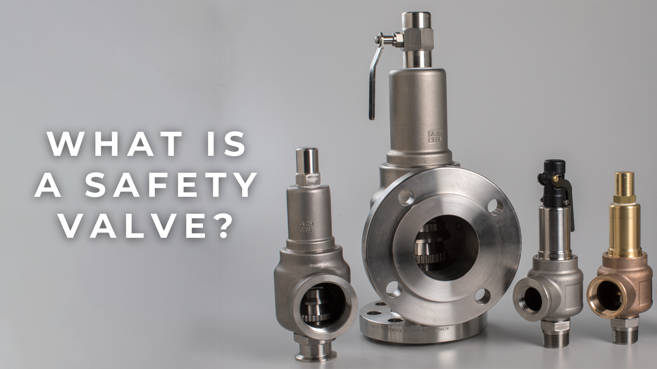
The principal type of device used to prevent overpressure in plants is the safety or safety relief valve. The safety valve operates by releasing a volume of fluid from within the plant when a predetermined maximum pressure is reached, thereby reducing the excess pressure in a safe manner.
1. Before the safety valve leaves the factory, we should adjust its opening pressure to reach the set value user specifies. If a user specifies the working pressure level of the spring, then we should adjust it according to the lower limit of the pressure level.
2. Before the safety valve is installed on the protected equipment, users must re-adjust it at the installation site to ensure the set pressure value of the safety valve meets the requirements.
3. In the range of the working pressure level of the spring specified by the nameplate, by turning the adjustment stem to change the compression amount of the spring, we can adjust the opening pressure.
5. To ensure the accuracy of opening pressure value, make sure the medium conditions, such as medium types and temperatures, are as close as possible to the actual operating conditions. When the medium type changes, especially when the dielectric aggregation is different (for example, from the liquid phase to the gas phase), the opening pressure often changes. When the operating temperature rises, the opening pressure is generally reduced. When it’s adjusted at room temperature and used for high temperature, the set pressure value at room temperature should be slightly higher than the required opening pressure value. How high the temperature should be has something to do with the valve structure and material selection, so it should be based on the manufacturer’s instructions.
6. The conventional safety valve is used to fix the additional backpressure. When adjusting opening pressure after the testing (at this time, the backpressure is atmospheric pressure), the set value should be required opening pressure minus additional backpressure.
By adding the 0.1 bar shut-off margin, the safety valve set pressure has to be 10% greater than 6.4 bar. For this example, this means that the safety valve’s set pressure has to be: The set pressure would therefore be chosen as 7.11 bar, provided that this does not exceed the MAWP of the protected system.
Thank you for reading our article and we hope it can help you better understand the adjustment of the opening pressure of the safety valve. If you want to learn more about safety valves, we would like to advise you to visit Adamant Valve homepage for more information.
Boiler explosions have been responsible for widespread damage to companies throughout the years, and that’s why today’s boilers are equipped with safety valves and/or relief valves. Boiler safety valves are designed to prevent excess pressure, which is usually responsible for those devastating explosions. That said, to ensure that boiler safety valves are working properly and providing adequate protection, they must meet regulatory specifications and require ongoing maintenance and periodic testing. Without these precautions, malfunctioning safety valves may fail, resulting in potentially disastrous consequences.
Boiler safety valves are activated by upstream pressure. If the pressure exceeds a defined threshold, the valve activates and automatically releases pressure. Typically used for gas or vapor service, boiler safety valves pop fully open once a pressure threshold is reached and remain open until the boiler pressure reaches a pre-defined, safe lower pressure.
Boiler relief valves serve the same purpose – automatically lowering boiler pressure – but they function a bit differently than safety valves. A relief valve doesn’t open fully when pressure exceeds a defined threshold; instead, it opens gradually when the pressure threshold is exceeded and closes gradually until the lower, safe threshold is reached. Boiler relief valves are typically used for liquid service.
There are also devices known as “safety relief valves” which have the characteristics of both types discussed above. Safety relief valves can be used for either liquid or gas or vapor service.
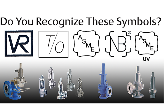
Nameplates must be fastened securely and permanently to the safety valve and remain readable throughout the lifespan of the valve, so durability is key.
The National Board of Boiler and Pressure Vessel Inspectors offers guidance and recommendations on boiler and pressure vessel safety rules and regulations. However, most individual states set forth their own rules and regulations, and while they may be similar across states, it’s important to ensure that your boiler safety valves meet all state and local regulatory requirements.
The National Board published NB-131, Recommended Boiler and Pressure Vessel Safety Legislation, and NB-132, Recommended Administrative Boiler and Pressure Vessel Safety Rules and Regulationsin order to provide guidance and encourage the development of crucial safety laws in jurisdictions that currently have no laws in place for the “proper construction, installation, inspection, operation, maintenance, alterations, and repairs” necessary to protect workers and the public from dangerous boiler and pressure vessel explosions that may occur without these safeguards in place.
The documents are meant to be used as a guide for developing local laws and regulations and also may be used to update a jurisdiction’s existing requirements. As such, they’re intended to be modifiable to meet any jurisdiction’s local conditions.
The American Society of Mechanical Engineers (ASME) governs the code that establishes guidelines and requirements for safety valves. Note that it’s up to plant personnel to familiarize themselves with the requirements and understand which parts of the code apply to specific parts of the plant’s steam systems.
High steam capacity requirements, physical or economic constraints may make the use of a single safety valve impossible. In these cases, using multiple safety valves on the same system is considered an acceptable practice, provided that proper sizing and installation requirements are met – including an appropriately sized vent pipe that accounts for the total steam venting capacity of all valves when open at the same time.
The lowest rating (MAWP or maximum allowable working pressure) should always be used among all safety devices within a system, including boilers, pressure vessels, and equipment piping systems, to determine the safety valve set pressure.
General guidance on proper installation may seem like common sense to experienced installers and inspectors. A few of the most important guidelines and best practices include:
Avoid isolating safety valves from the system, such as by installing intervening shut-off valves located between the steam component or system and the inlet.
Contact the valve supplier immediately for any safety valve with a broken wire seal, as this indicates that the valve is unsafe for use. Safety valves are sealed and certified in order to prevent tampering that can prevent proper function.
Avoid attaching vent discharge piping directly to a safety valve, which may place unnecessary weight and additional stress on the valve, altering the set pressure.
The primary role of a safety relief valve is to prevent over-pressure situations in pressurized vessels or systems. If the tank’s relief valve fails, it can lead to an accident that destroys property, life, or landscape.
The National Board of Boiler and Pressure Vessel Inspectors is one of the governing bodies for the testing and/or repair of ASME Safety Relief Valves.
You, as the owner of the valve, can test it, but it must be done in accordance with the National Board Inspection Code and your state’s and/or local regulations.
Based on the National Board Code, which bases their inspection intervals on what type of service the valve is used for, the following intervals are suggested:
Also, keep in mind that this piping should be oriented so that no liquid relieved through this piping can flow back and rest on the ASME safety relief valve’s outlet port.
The ASME relief valves are set to fully open at its “set” pressure but will begin to partially open before then – normally at 10% below its set pressure.
If your valve is allowed to do this, trash and/or corrosion can set in over time which could prevent the valve from either closing completely or from fully opening, either of which is not a favorable solution.

The importance of installing the correct temperature and pressure relief valve on a water heater or hot-water storage tank cannot be overemphasized. This applies to new vessels as well as relief valve replacements. The importance of installing a valve with the correct pressure rating is common knowledge to many, but it also is crucial to install a valve with the appropriate relieving capacity rating. Many times the capacity factor is overlooked.
The code of construction of the vessel itself can play a key role in choosing the correct valve capacity. Unfortunately, the code of construction criteria is unknown to many and overlooked by others.
As the name indicates, T&P relief valves are designed to protect water heaters and hot-water storage vessels against excess temperature and excess pressure. Most valves are rated at 150 psi and 210° F, but their capacity ratings vary greatly. Sometimes, an additional T&P relief valve with a lower temperature and pressure rating (typically 180° and 100 psi) is installed in a plastic hot-water distribution system to protect the piping system itself. A T&P relief valve is, in essence, a dual device because it meets the code requirements of an individual temperature relief valve and an individual pressure relief valve.
The temperature function of the valve is controlled by an internal thermostatic element. At 210°, the internal expansion within the probe causes a piston to push against the valve’s disk. The spring is overpowered and compressed, and the water escapes between the disc and seat. The extremely hot water within the tank is forced out under pressure as cold water replenishes the discharge. The cold water rushing into the vessel lowers the water temperature, and when the temperature drops back below 210°, the valve is reseated.
The pressure function of the valve also is controlled by the spring, disc and seat. When the pressure exceeds the valve’s pressure rating, the water pressure overcomes the spring. The spring is compressed (just like a typical pressure-only relief valve) and the water escapes between the disc and seat.
It is important to note that when the valve is weeping or dripping, the cause is usually excessive pressure. Many times this is caused by thermal expansion. A T&P relief valve is not designed to nor should it be used to continuously control thermal expansion within a closed system. Thermal expansion of hot water within a closed system should be controlled with the installation of an approved expansion tank or by other means permitted by local code.
Dripping may continue because of debris within the valve, such as a build-up of calcium in the seat, and over time, large mineral deposits can make the valve ineffective. When a valve is discharging a large quantity of water, the cause is almost always excessive temperature.
The only way to determine the maximum allowable working pressure of a vessel is to read the nameplate that is attached to it. The pressure on the valve’s tag must be compared to the pressure on the vessel’s nameplate. The pressure rating of the relief valve must be equal to or less than the MAWP of the vessel. Most water heaters have an MAWP of 150 psi; however, some are rated higher, typically 160 psi. Some storage vessels have a lower pressure rating; they are commonly rated 125 psi.
Another factor in determining the pressure rating of the T&P relief valve is the code itself. Model codes require the T&P relief valve be set no higher than 150 psi. Therefore, a water heater with a MAWP of 160 psi still requires a T&P relief valve set at 150 psi, even though the vessel is designed and built to withstand a higher pressure.
The relieving capacity of the valve must be equal to or greater than the Btu/hr. of the vessel. The thermal capacity of the water heater can be found on its nameplate along with the MAWP. The confusion in choosing the correct T&P relief valve resides on the relief valve’s nametag itself. T&P relief valves display two relieving capacity ratings. One is the American Society of Mechanical Engineers/National Board of Boiler and Pressure Vessel Inspectors rating, and the other is the Canadian Standards Association/American National Standards Institute Z21.22 rating.
The relieving capacity of the valve’s ASME/NB rating is established by Section IV, Part HG of the “ASME Boiler and Pressure Vessel Code.” The code reads, “Capacity certification tests of safety relief valves for water heating and hot-water supply boilers shall be conducted at 110% of the pressure for which the valve is set to operate.” So the capacity of a T&P relief valve set at 150 psi is based on its vessel pressurized to 165 psi.
The ASME/NB relieving capacity rating is more lenient than the CSA rating. The CSA rating is based on 15 psi of steam pressure, so the CSA rating will always be lower and, therefore, more stringent than the ASME/NB rating. ASME HLW water heaters are built to a more stringent code of construction than ANSI Z21 water heaters. The use of a valve’s ASME/NB capacity rating to protect an ANSI-built vessel could present a potentially dangerous condition.
Chapter 5, Section 504.4 of the 2012 International Plumbing Code specifically requires relief valves to conform to the Z21.22 standard; the code is very concise. Some of the other model codes are not as clear as the IPC. Section 504 of the Uniform Plumbing Code only references an approved, listed device installed in accordance with the listing and the manufacturer’s installation instructions; however, the Z21.22 standard is included in Table 1401.1.
While the 2012 National Standard Plumbing Code makes no distinction between the use of the ASME/NB and CSA capacity ratings, the 2015 NSPC will limit the use of the ASME/NB relieving capacity ratings to ASME vessels only.
If permitted by the local adopted code, AMSE/NB relieving capacities should only be considered for ASME vessels. The more restrictive CSA relieving capacities are always the safer choice.
Industrial equipment often uses either safety or relief valves to prevent damaging pressure levels from building up. Though they perform similar functions, there are some critical differences between safety and relief valves. Understanding these two valves’ differences is essential for proper pressure system operation. So here we discuss the pressure safety valve vs pressure relief valve.
A pressure relief valve is a device that releases pressure from a system. The relief valve is generally immune to the effects of back pressure and must be periodically stripped down. Pressure relief valves are one the essential parts of a pressure system to prevent system failures. They are set to open at a predetermined pressure level. Each pressure system has a setpoint that is a predetermined limit. The setpoint determines when the valve will open and prevents overpressure.
Pressure relief valves are typically used in gas or liquid systems where there is a need to prevent excessive pressure from building up. When the pressure in the system reaches a certain level, the valve will open and release the pressure. Pressure relief valves are an essential safety feature in many designs and can help to prevent damage to the system or components.
PRVs are generally considered to be safe and reliable devices. However, before installing a PRV in a system, some potential disadvantages should be considered. Here are five pros and cons of pressure relief valves:
Pros: Pressure relief valves are anessential safety feature in many systems. They protect against over-pressurization by relieving excess pressure from the system. This can help to prevent severe damage or even explosions.
Pressure relief valves can help to improve the efficiency of a system. The system can operate at lower overall pressure by relieving excess pressure and saving energy.
Pressure relief valves can be used as a safety device in systems that are susceptible to overpressurization. By relieving pressure before it builds up to a dangerous level, they can help to prevent accidents and injuries.
Cons: Pressure relief valves can be a potential source of leaks. If not properly maintained, the valve may not seat properly and can allow fluids or gasses to escape.
Pressure relief valves can sometimes cause problems if they do not open or close properly. This can lead to process disruptions and may cause safety issues.
A pressure safety valve is a device used to release pressure from a system that has exceeded its design limit. This safety valve is a fail-safe device. This type of valve is typically used in systems that contain fluids or gasses under high pressure. Pressure safety valves are designed to open and release pressure when the system has exceeded its maximum pressure limit. This helps to prevent the system from rupturing or exploding.
Pressure safety valves are an essential part of many different types of systems and can help keep both people and property safe. If anyone is ever in a situation where they need to release pressure from a system, it is essential to know how to use a pressure safety valve correctly.
A pressure safety valve (PSV) is a type used to relieve a system’s pressure. PSVs are commonly used in chemical and process industries, as well as in some kinds of pressure vessels. There are both advantages and disadvantages to using a PSV. Some of the pros of using a PSV include: PSVs can help to prevent overpressurization, which can be dangerous.
A safety valve is a pressure relief device used to prevent the over-pressurization of a system. On the other hand, a relief valve is a device used to relieve pressure from a system that is already overpressurized. Function Of Pressure Relief Valve Vs Safety Valve
The function of a pressure relief valve is to protect a system or component from excess pressure. A safety valve, on the other hand, is designed to protect from overpressurization. Both types of valves are used in various industries, but each has unique benefits and drawbacks.
Pressure relief valves are typically used in systems where a small amount of overpressure can cause damage. On the other hand, safety valves are designed for systems where overpressurization could be catastrophic. Both valves have advantages and disadvantages, so choosing the right type of valve for the specific application is essential.
Relief valves are usually set to open at a specific pressure and will close once the pressure has been relieved. Safety valves are similar in that they are also used to protect equipment from excessive pressure. However, safety valves are designed to stay open until they are manually closed. This is because safety valves are typically used in applications where it is not safe to have a closed valve, such as in a gas line. Operation Of Safety Relief Valve Vs Pressure Relief Valve
Two types of valves are commonly used in industrial settings: relief valves and safety valves. Both of these valves serve essential functions, but they operate in different ways.
Relief valves are designed to relieve pressure build-up in a system. They open when the system pressure reaches a certain point, which allows excess pressure to be released. On the other hand, safety valves are designed to prevent accidents by preventing system pressure from getting too high. They open when the system pressure reaches a certain point, which allows excess pressure to be released before an accident can occur.
So, which valve is better? That depends on the situation. A relief valve is the better option to protect the system from pressure build-up. If anyone need to protect the system from accidents, then a safety valve is the better option Setpoint Of Pressure Relief Valve Vs Safety Relief Valve
The relief valve is made to open when it reaches a specific pressure, commonly described as a “setpoint”. Setpoints shouldn’t be misinterpreted as the pressure set. A setpoint on a relief valve is set to the lowest possible pressure rating, which means it is set to the lowest system pressure before an overpressure situation is observed. The valve will open as the pressure increases to a point higher than the setpoint. The setting point is determined as pounds per square inch (PSIG) and should be within the maximum allowed operating pressure (MAWP) limits. In safety valves, the setpoint is typically placed at about 3 percent over the working pressure level, whereas relief valves are determined at 10 percent.
No, the safety valve and relief valve can not be used interchangeably. Though both valves are seal butterfly valve and used for safety purposes, they serve different functions. A safety valve relieves excess pressure that builds up in a system, while a relief valve regulates the pressure in a system.
Knowing the difference between these two types of valves is essential, as using the wrong valve for the intended purpose can potentially be dangerous. If unsure which type of valve to use, it is always best to consult with a professional.
A few key points help us understand the safety valve vs pressure relief valve. Safety valves are designed to relieve pressure in a system when it gets too high, while relief valves are designed to relieve pressure when it gets too low. Safety valves are usually set to open at a specific pressure, while relief valves are generally open at a particular vacuum. Safety valves are typically intended for one-time use, while relief valves can be used multiple times. Choose the trusted valve manufactureraccording to the specific business needs.
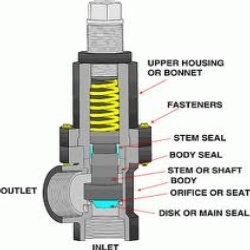
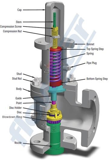
The main parts of a safety valve are the valve body, set spring, disc, seat & stem with other parts such as an adjustment screw to adjust the spring force which changes the opening pressure set point.
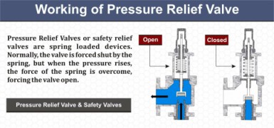
The pressure safety valves work by having a pre-set compression in a spring acting on a disc which closes an opening called a seat. The spring force is set so that the valve will open when a specific pressure is reached in the system which is being protected. Once this pressure is exceeded, the disc rises, which opens the seat and allows the air/steam/liquid to vent off until the valve re-seats. The valve is designed to re-seat at a pressure lower than the set-pressure.
Valves are sized according to the applicable standards (API/ISO/DIN etc.) required for the area/application of the protected system. Sometimes specific sizing is required if the application falls outside of those covered by the standards.
There are many different types of safety valves depending on the application of the protected system. The most common is the simple spring loaded pressure relief valve, however for low pressure (atmospheric) tanks relief valves can be weight loaded.
A safety valve is designed to work in an emergency situation and generally relieves to atmosphere. A pressure relief valve may have a less critical application.
It doesn’t unless designed to. Depending on manufacturer there can be a 2-5% tolerance in opening pressure. There is also an over pressure require to fully open a valve above the opening/set pressure.
It is the pressure at which the safety valve is set at on the test bench without back pressure. The pressure at which a safety relief valve, intended for high temperature service, is set on a test rig using a test fluid at ambient temperature.
It is best to perform test a safety valve on a special machine for same. There are in-situ testers which can be used with agreement from the site insurers. There are also recommended material visual inspections depending on the service.
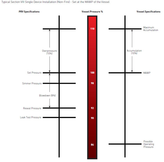
Blowdown is the difference between set pressure and reseating pressure of a safety valve expressed as a percentage of set pressure. Typical blowdown values as defined in codes and standards are -7% and -10%, ranging from -4% to -20% depending on the code and service (steam, gas or liquid)
There are a few API standards that apply to relief valves, depending on whether they are flanged, reference to seal tightness and how they are used in pressure relieving systems
Please consult the applicable standard for the specific application. Most manufacturers will have a sizing programme for the relief capacity of their vents, but the calculation of the required venting capacity must be completed by a qualified person from the end-user side.

The SRLQ liquid safety relief valve is a unique solution providing overpressure protection of vessels containing liquid. While traditional safety relief valves are designed for vapor use only the SRLQ is unique in that is it designed specifically for use with liquids. Safety relief valves are designed to relieve pressure in a vessel when the set pressure is exceeded, preventing potential damage to equipment and injury to personnel. After opening, these valves re-seat when the pressure in the vessel is below the valve’s closing pressure. The liquid safety relief valves (SRLQ) are designed and constructed to meet the requirements of Section VIII ASME Boiler and Pressure Vessel Code and ANSI/ASHRAE 15 code requirements and bear the ASME code symbol. Employing proven principles of design, these safety relief valves are highly reliable and dependable. Precision machined moving parts of stainless steel, and a PTFE disc prevent sticking due to corrosion or cold welding and assure valve opening at the set pressure long after installation.

High-pressure relief valves fulfill a critical safety function in multiple applications, ranging from petrochemical to power, marine and aerospace industries. Regardless of the application, certain primary features can help guide engineers when selecting a durable high-pressure relief valve that will help avoid catastrophic failure to protect your workers’ health and safety while also preserving capital equipment.
A relief valve functions as an operational safety feature, to help control and regulate the flow of high-pressure fluids and gases. It is designed to vent off extra pressure, whether from gas or a liquid. The design triggers the valve to open once a system reaches a predetermined set pressure.
This protects systems from experiencing pressures that exceed their design limits. Once a system reaches that predetermined level or valve set pressure, the relief valve opens, and a portion of the liquid or gas is removed from the system by diverting it through an outlet in the valve.
The relief valve helps maintain safe pressure levels to prevent potential damage or catastrophic failure. Once system pressure drops to its predetermined normal level, the relief valve closes or “reseats” until it is needed again. While a relief valve functions as a safety feature, it differs from a safety valve which only triggers in an emergency.
A safety valve opens instantly to its full venting capacity while a high-pressure relief valve opens gradually when system pressure reaches the preset level.
A catastrophic failure could mean loss of capital equipment such as pipes if the pressure doesn’t diminish. Pressure build up, if unrelieved, can lead to more serious consequences such as an explosion, potentially harming personnel and causing more widespread damage to equipment and surroundings.
High-pressure relief valves are found in several different industries including marine applications on naval and commercial vessels, aerospace, industrial gas, the petrochemical industry, power plants and many industrial applications as well.
The set pressure limit is the threshold that triggers the high-pressure relief valve action. For example, if the normal system pressure is 3000 PSI the engineer might determine the set pressure limit is 3300 PSI. Once pressure reaches that threshold it triggers the relief valve which then vents the excess liquid or gas. Consistent triggering of the relief valve often indicates a problem with the system.
Connection size and type—The connection of the valve or valve size needs to correspond to the size of the discharge piping. Operators must also determine the connection type for the inlet and outlet ends, typically threaded or flanged.
Material selection, design and testing will reveal the ability of the valve to withstand shock and vibration without triggering its action. Naval vessels require parts such as relief valves pass specifications for shock and vibration.
This particularly plays a role in material selection for the valve construction when it will come into contact with a corrosive or abrasive substance. An example of this would be a marine relief valve that can or will regularly encounter salt water. All CPV Mfg. high-pressure relief valve specified for marine purposes are manufactured of bronze.
This relates to the relief capacity of the valve. When the orifice size is smaller, the relief valve can rate to a higher pressure but relieve less capacity. The larger the orifice, the lower the pressure but the higher the relief capacity of the valve.
All relief valves manufactured by CPV have a positive reseating, which means after it blows at pressure, it reseats itself or reseals once the pressure drops into the normal range. This reseating capability allows for continuous operations. Look for a soft seating design which acts as a bubble tight seal, versus a metal-to-metal interface, which can be prone to leaking.
A sensitive spring, such as those incorporated into a CPV high-pressure relief valve, allows the operator to adjust the release for a very narrow PSI range. For example, the spring itself might be rated for 1,000 to 2,000 PSI, but the sensitivity enables the operator to set it at a specific target, such as 1,015 PSI, for example.
Add to this testing capabilities, and the cooperative efforts of the engineering design team and the valve manufacturer can produce a valve with the most accurate control of the blowdown pressure setting.
CPV manufactures relief valves in two different series: the 150 series and our flagship O-SEAL® line. The 150 series is a line of soft-seated female threaded relief valves with set pressures that range from the low end of 5 PSI up to 300 PSI.
The O-SEAL® line of soft-seated valves and separable fittings allow for positive control of high-pressure liquids and gases. This line offers leak proof performance from vacuum up to 6000 PSI (414 bar).
CPV has been supplying high-pressure relief valves to the U.S. Navy for mission critical applications since the 1950s. Each individual valve built by CPV Manufacturing undergoes testing, not random or batch testing, but each valve.
Valves must meet a safety factor for the pressure rating of four to one. If a valve is rated for 6,000 PSI for example, the valve strength is up to or in excess of 24,000 PSI. In addition, all valves meet the ASME Boiler and Pressure Vessel Code. Our valves are over-engineered to exceed the pressure strength rating, for the utmost in reliability.
Trust CPV Manufacturing for durable, reliable, high-pressure valves that meet the stringent requirements of the U.S. Navy, found in service in submarines, aircraft carries and other vessels throughout the fleet. We can work within your specifications or consult for customized projects and applications.
This website is using a security service to protect itself from online attacks. The action you just performed triggered the security solution. There are several actions that could trigger this block including submitting a certain word or phrase, a SQL command or malformed data.

In the process industry, both terms refer to safety devices, which generally come in the form of valves, cylinders, and other cylinders that protect people, property, and the environment. Safety valves and relief valves are integral components of process safety. However, they are used for almost identical purposes. Their main difference lies in their operating mechanisms.
In the event of an overpressure, a safety valve or pressure relief valve (PRV) protects pressure-sensitive equipment. It is recommended to strip down relief valves regularly and prevent serious damage due to backpressure. Pressure relief valves are a crucial part of any pressurized system. In order to prevent system failures, you can set the pressure to open at predetermined levels. A setpoint, also known as a predetermined design limit, is set for all pressure systems. When the setpoint is exceeded, an overpressure valve opens.
There are various types of safety valves used in several types of industries, including power plants, petrochemical plants, boilers, oil and gas, pharmaceuticals, and more. Using safety valves helps to prevent accidents and injuries that can harm people, property, and processes. Pressure builds up in vessels and systems automatically when the device is activated above a preset level. Safety valves must be configured so that their prescribed pressure is exceeded in order for them to function (i.e., relieve pressure). Ideally, excess pressure should be released either to the atmosphere or back into the pneumatic system to prevent damage to the vessel. In addition, excess pressure should be released to keep pressure within a certain range. As soon as a slight increase in pressure above the desired limit has lifted the safety valve, it opens.
Valve relief removes excessive pressure from a system by limiting its pressure level to a safe level. Often referred to as pressure relief valves (PRVs) or safety relief valves, these valves provide relief from pressure. The purpose of a relief valve is, for example, to adjust the pressure within a vessel or a system so that a specific level is maintained. The goal of a relief valve, unlike a safety valve, is not to prevent damage to the vessel; rather, it is to control the pressure limit of a system dynamically depending on the requirements. Conversely, safety valves have a maximum allowable pressure set at a certain level, which allows escaping liquid or gas whenever the pressure exceeds it, eliminating damage to the system. It is imperative that safety valves are installed in a control system to prevent the development of pressure fluctuations that can cause property damage, life loss, and environmental pollution.
The hydraulic system relies on a pressure relief system in order to regulate the running pressure. By allowing excess pressure to escape from the pressurized zone, pressure relief valves and safety valves prevent overpressure when the pressure in the system reaches a predefined limit. By venting excess pressure through a relief port, or returning it through a return line, a pneumatic system can enable the excess pressure to escape into the atmosphere. Pump-driven pressure generators and control media that cannot be vented into the atmosphere are typical examples of this type of application.
Excess pressure may be relieved from the system using relief valves and safety valves. The valve opening increases proportionally as the vessel pressure increases with the relief valve. Gradually opening the valve rather than abruptly releases only a prescribed amount of fluid. As pressure is reduced, the release proceeds at this rate until the pressure drops. By contrast, an emergency safety valve operates automatically when a predetermined pressure is reached in the system, preventing a catastrophic system failure. When the system is under excessive stress, the safety valve regulates the pressure within the system and prevents overpressure.
Defining a “setpoint” is the process of defining a pressure level which triggers the device to vent excess pressure. Setpoint is different from pressure. Overpressure is prevented by setting these devices lower than the highest pressure the system can handle before overpressure occurs. Setting the device below this pressure prevents overpressure. The valve opens when pressure rises above the setpoint. A setpoint also known as the maximum allowable working pressure (MAWP) cannot be exceeded when deciding the pressure in pounds per square inch (PSIG). The adjustment points for safety valves are generally 3 percent above working pressures, while adjustment points for relief valves are 10% above working pressures.
Pressure in an auxiliary passage can be controlled by a safety valve as well as a relief valve by releasing excess pressure. Safety valves of this type are pressure-sensitive and reliable. Safety valves can be categorized according to their capacity and setpoint, although both terms often refer to safety valves. Self-opening devices open automatically when maximum allowable pressure has been reached rather than being manually activated to prevent over-pressurizing. Contrary to relief valves, safety valves are typically used for venting steam or vapor into the atmosphere. Relief valves regulate fluid flow and compressed air pressure and gases, whereas safety valves typically regulate steam and vapor venting. Put simply, relief valves are used for more gradual pressure control requiring accurate, dynamic systems, whereas safety valves are used for one set to prevent damage to a system.
For pressure control applications that require dynamic setpoints and therefore varying pressure limits, our Electronic Relief Valve is the appropriate solution. This device accepts a control voltage to dynamically set the relief pressure setpoint. Traditional relief valves are set manually, so that a technician must adjust the relief valve and have a pressure gauge to find the accurate setpoint. The Kelly Pneumatic Electronic Relief Valve allows an electronic control system to quickly and safely command a dynamic maximum pressure based on feedback from current system specifications. The Kelly Electronic Relief Valve also has an optional feedback signal representing the current pressure in the system. This allows the control system to dynamically respond to changing conditions.

(a) Qualifications of individual who adjusts. Safety relief valves shall be set and adjusted by a competent person who is thoroughly familiar with the construction and operation of the valve being set.
(b) Opening pressures. At least one safety relief valve shall be set to open at a pressure not exceeding the MAWP. Safety relief valves shall be set to open at pressures not exceeding 6 psi above the MAWP.
(c) Setting procedures. When setting safety relief valves, two steam gauges shall be used, one of which must be so located that it will be in full view of the persons engaged in setting such valves; and if the pressure indicated by the gauges varies more than 3 psi they shall be removed from the boiler, tested, and corrected before the safety relief valves are set. Gauges shall in all cases be tested immediately before the safety relief valves are set or any change made in the setting. When setting safety relief valves, the water level shall not be higher than
(d) Labeling of lowest set pressure. The set pressure of the lowest safety relief valve shall be indicated on a tag or label attached to the steam gauge so that it may be clearly read while observing the steam gauge.

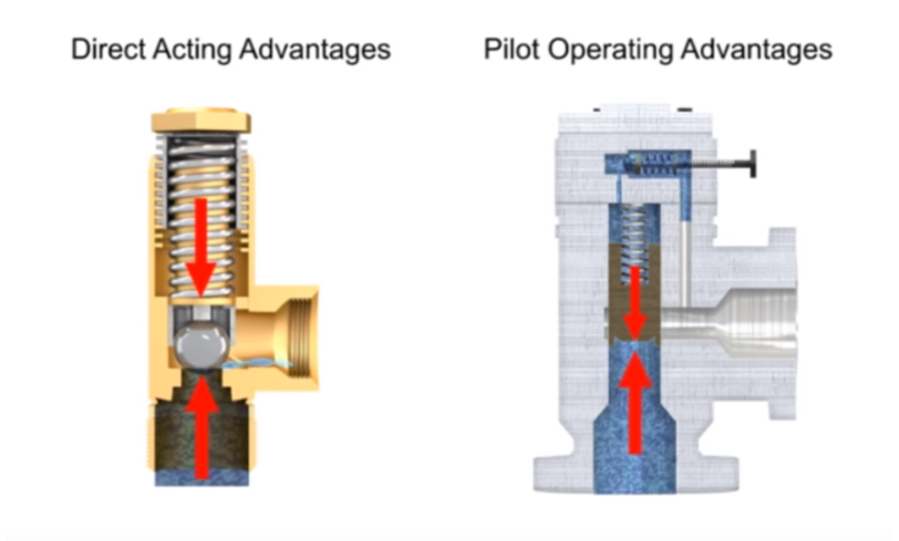
The other advantage of POPRV’s is that whether a snap-acting or modulating pilot is used, the presence of superimposed back pressure does not affect the opening pressure when the valve is in service. This is unlike direct spring safety relief valves, which require expensive and fragile bellows to protect against backpressure.
The modern POPRV can be used confidently in ASME Section VIII applications. POPRV’s provide a leak-free system operation very close to the PRV set pressure. A non-flowing pilot design assures that the POPRV will relief consistently within code tolerances even in “dirty” service applications, thus lower cost of ownership. Since process pressure is used to provide sealing force, a lighter unit weight and smaller size results in a lower cost of installation. POPRV’s provide advanced, reliable, and efficient overpressure protection, utilizing a product technology designed for a wide range of ASME Section VIII applications.
This website is using a security service to protect itself from online attacks. The action you just performed triggered the security solution. There are several actions that could trigger this block including submitting a certain word or phrase, a SQL command or malformed data.

A pressure safety valve (PSV) is a failsafe used to protect people, property and processes from process over pressure. Designed to open immediately to relieve pressure when system pressure reaches a certain level, known as the set pressure, they then close back up to prevent the further release of fluid or gas once normal conditions have been restored. PSVs are essential to the protection of lives and equipment, particularly in the oil & gas, power generation, water/wastewater, aerospace/aviation, steel manufacturing, and chemical/plastics industries. They are purely mechanical so they’re capable of operating at all times and are considered the last resort in preventing catastrophic failure in systems under over pressure conditions.
As the final link in the safety chain, safety valves need frequent testing to ensure they’re in good operating condition and functioning properly. The mechanical parts can stick closed, wear over time and exposure to contaminants and corrosion can affect the resealing or closing of the valve seat after release that could result in a leak. Depending on the industry in which they’re being used, it’s recommended that they’re tested at least every 1-3 years, or more frequently depending on previous inspection history.
PSVs should be tested at their operating pressures and temperatures. A test can be performed "in-situ," while the valve is still in service, but the set pressure is often challenging to create in the field so they’re more commonly removed from the system entirely and taken into a lab/test center for bench testing.
During a conventional PSV test, a technician carefully supplies rising pressure to the valve until it pops (or "cracks"), compares that pressure to the set pressure, and records the results. The goal is to ensure the valve will open and perform its function at the desired set pressure and that the reseal event happens at the desired lower pressure.
To get started you’ll need to connect your PSV, a pressure reference gauge, and an external pressure source. Be sure to follow ASME Section VIII standards for the type of valve being tested.
Step 1: Before you start testing, determine the set pressure of the PSV. Every PSV has a set pressure engraved on the tag riveted onto the body, which is the reading at which the valve should pop open to quickly release pressure. Be sure that the gauge you’re using has the correct measuring range to accommodate the set pressure.
Step 3: Slowly decrease the flow of pressure and record the reseating pressure value, or the pressure point at which the valve closes. If the volume of your pressure source is too low, this will happen instantly and the lower pressure may be difficult to record.
Though the basic PSV testing procedure is relatively easy to perform, results are certified by a technician based on simple observation with little hard data to back it up, and certificates are signed and issued with little to no traceability other than the technician’s word. Even two highly trained technicians observing the same test may record different results, which highlights the inherent potential for human error in this type of standard PSV test.
Accurate testing of PSVs requires extremely precise measurement of the cracking pressure when the valve lifts, and the exact moment when the valve reseats. The FieldLab’s unique PSV/PRV test mode detects the PSV crack pressure and reseat pressure by logging pressure at 200 times per second - far quicker than the logging rate on other devices. It allows the technician to conduct the test and record all of the data directly on the gauge, and then transfer it electronically to a PC where a test report with graphs, customer data, tag data and other required information can be output and shared. It can also perform a leak test and make a judgement of pass or fail based on the ASME standard.
Though the terms Pressure Relief Valve (PRV) and Pressure Safety Valve (PSV) are often used interchangeably, it"s important to understand that PRVs are designed to control pressure in a system. They open gradually in proportion to increasing pressure and are mainly used in fluid or compressed air systems. A PSV is strictly a safety mechanism with no attempt to control the pressure. PSVs open immediately and fully with a "pop action" when the set pressure is reached.


 8613371530291