
back pressure safety valve free sample
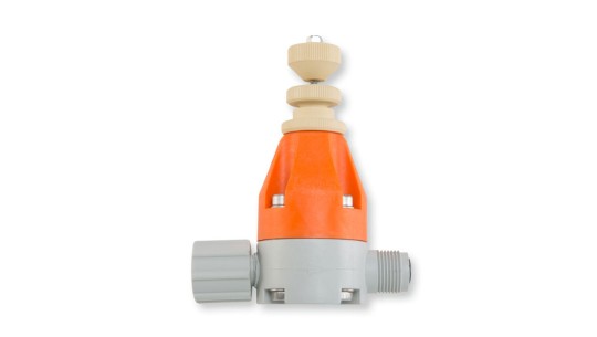
Back pressure valve / relief valve for fitting directly on the pump"s dosing head with the functions:Back pressure valve, opening pressure approx. 1.5 bar with free outlet or priming pressure at the suction end (black rotary dial)
The multifunctional valve is operated by free-moving rotary dials that automatically return to their original position when released by the operator. This means operation is possible even when access is difficult. The multifunctional valve is made of PVDF and can be used to meter almost any chemical.
Caution: Back pressure valves are not absolutely leak-tight shut-off devices! It is essential that you observe the installation notes in the operating instructions!
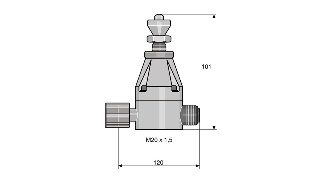
SealFKM and EPDM (loose)TypeRelief opening pressure *Connector sizeBypass connectorOrder no.*The relief opening pressure given above is the pressure at which the valve starts to open. The pressure may be up to 50% more than this before the valve is fully open depending on the type of pump.Size I16 bar6-126 x 4792011
Adjustable back pressure valve for fitting directly onto the dosing head to generate a constant back pressure. For accurate metering with a free outlet and with priming pressure on the suction side.
Please note: Back pressure valves are not absolutely leak-tight shut-off devices! It is essential that you observe the installation notes in the operating instructions!Applications:Metering pump alpha, beta, gamma/ X, gamma/XL, Pneumados b, EXTRONICTypeadjustable pressure max.Connector widthMaterialOrder no.
Adjustable back pressure valve for installation in the metering line to generate a constant back pressure for precise metering with a free outlet and with priming pressure on the suction side
When used as a back pressure valve in long lines to avoid resonance vibrations: Install at the end of the metering line or select a set pressure greater than the line pressure loss
Use in conjunction with pulsation damper only with a free outlet and short metering line. Use type DHV-U when using a pulsation damper with back pressure or long lines.
Please note: Back pressure valves are not absolutely leak-tight shut-off devices! It is essential that you observe the installation notes in the operating instructions!Applications:Metering pumps alpha, beta , gamma/ X, gamma/XL, Pneumados b, EXTRONICTypeadjustable pressure max.Connector widthMaterialOrder no.
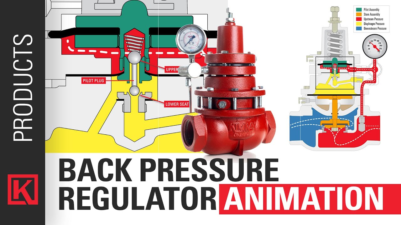
When selecting a pressure relief valve (PRV) for any application, many factors need to be taken into consideration. One of the most important — and least well understood — is back pressure. This article explains what back pressure is and how it affects the performance of PRVs.
Superimposed back pressure. Superimposed pressure is the pressure in the discharge header before the pressure relief valve opens. Depending on the system, superimposed back pressure can be constant or variable.
Back pressure can significantly affect a valve’s performance by reducing both its set pressure and its capacity. Too much back pressure can result in chatter (rapid opening and closing), which can damage the valve.
For conventional relief valves, back pressure reduces set pressure directly on a one-to-one basis. For example, a valve with a set point at 100 psig that is subjected to 10 psig of back pressure will not reach set point until the system pressure reaches 110 psig. In this example, if the set point is not adjusted to compensate for the back pressure, this can mean that valves are operating at a level that is higher than their maximum allowable working pressure (MAWP).
The effect of back pressure on valve capacity is much more significant. Typically, high back pressure can decrease the PRV’s capacity by approximately 50%.
For balanced bellows relief valves, the bellows mitigate the effects of back pressure up to a certain point. These valves are generally not affected unless the back pressure exceeds 30 or 35% of set pressure. The tradeoff is that they can fail at higher pressures.
Back pressure needs to be accounted for when sizing a PRV. In general, back pressure should notexceed 10% of the set pressure, especially for conventional relief valves.
The key to handling back pressure is to take it into consideration when sizing and selecting your valves. If you know that the back pressure in your system will be higher than the recommended limits, you may need to select a larger valve.
Don’t risk damage to your valves or other equipment caused by too much back pressure. Contact us for assistance selecting the right valve for your application.

A safety valve must always be sized and able to vent any source of steam so that the pressure within the protected apparatus cannot exceed the maximum allowable accumulated pressure (MAAP). This not only means that the valve has to be positioned correctly, but that it is also correctly set. The safety valve must then also be sized correctly, enabling it to pass the required amount of steam at the required pressure under all possible fault conditions.
Once the type of safety valve has been established, along with its set pressure and its position in the system, it is necessary to calculate the required discharge capacity of the valve. Once this is known, the required orifice area and nominal size can be determined using the manufacturer’s specifications.
In order to establish the maximum capacity required, the potential flow through all the relevant branches, upstream of the valve, need to be considered.
In applications where there is more than one possible flow path, the sizing of the safety valve becomes more complicated, as there may be a number of alternative methods of determining its size. Where more than one potential flow path exists, the following alternatives should be considered:
This choice is determined by the risk of two or more devices failing simultaneously. If there is the slightest chance that this may occur, the valve must be sized to allow the combined flows of the failed devices to be discharged. However, where the risk is negligible, cost advantages may dictate that the valve should only be sized on the highest fault flow. The choice of method ultimately lies with the company responsible for insuring the plant.
For example, consider the pressure vessel and automatic pump-trap (APT) system as shown in Figure 9.4.1. The unlikely situation is that both the APT and pressure reducing valve (PRV ‘A’) could fail simultaneously. The discharge capacity of safety valve ‘A’ would either be the fault load of the largest PRV, or alternatively, the combined fault load of both the APT and PRV ‘A’.
This document recommends that where multiple flow paths exist, any relevant safety valve should, at all times, be sized on the possibility that relevant upstream pressure control valves may fail simultaneously.
The supply pressure of this system (Figure 9.4.2) is limited by an upstream safety valve with a set pressure of 11.6 bar g. The fault flow through the PRV can be determined using the steam mass flow equation (Equation 3.21.2):
Once the fault load has been determined, it is usually sufficient to size the safety valve using the manufacturer’s capacity charts. A typical example of a capacity chart is shown in Figure 9.4.3. By knowing the required set pressure and discharge capacity, it is possible to select a suitable nominal size. In this example, the set pressure is 4 bar g and the fault flow is 953 kg/h. A DN32/50 safety valve is required with a capacity of 1 284 kg/h.
Where sizing charts are not available or do not cater for particular fluids or conditions, such as backpressure, high viscosity or two-phase flow, it may be necessary to calculate the minimum required orifice area. Methods for doing this are outlined in the appropriate governing standards, such as:
Coefficients of discharge are specific to any particular safety valve range and will be approved by the manufacturer. If the valve is independently approved, it is given a ‘certified coefficient of discharge’.
This figure is often derated by further multiplying it by a safety factor 0.9, to give a derated coefficient of discharge. Derated coefficient of discharge is termed Kdr= Kd x 0.9
Critical and sub-critical flow - the flow of gas or vapour through an orifice, such as the flow area of a safety valve, increases as the downstream pressure is decreased. This holds true until the critical pressure is reached, and critical flow is achieved. At this point, any further decrease in the downstream pressure will not result in any further increase in flow.
A relationship (called the critical pressure ratio) exists between the critical pressure and the actual relieving pressure, and, for gases flowing through safety valves, is shown by Equation 9.4.2.
For gases, with similar properties to an ideal gas, ‘k’ is the ratio of specific heat of constant pressure (cp) to constant volume (cv), i.e. cp : cv. ‘k’ is always greater than unity, and typically between 1 and 1.4 (see Table 9.4.8).
For steam, although ‘k’ is an isentropic coefficient, it is not actually the ratio of cp : c. As an approximation for saturated steam, ‘k’ can be taken as 1.135, and superheated steam, as 1.3. As a guide, for saturated steam, critical pressure is taken as 58% of accumulated inlet pressure in absolute terms.
Overpressure - Before sizing, the design overpressure of the valve must be established. It is not permitted to calculate the capacity of the valve at a lower overpressure than that at which the coefficient of discharge was established. It is however, permitted to use a higher overpressure (see Table 9.2.1, Module 9.2, for typical overpressure values). For DIN type full lift (Vollhub) valves, the design lift must be achieved at 5% overpressure, but for sizing purposes, an overpressure value of 10% may be used.
For liquid applications, the overpressure is 10% according to AD-Merkblatt A2, DIN 3320, TRD 421 and ASME, but for non-certified ASME valves, it is quite common for a figure of 25% to be used.
Backpressure - The sizing calculations in the AD-Merkblatt A2, DIN 3320 and TRD 421 standards account for backpressure in the outflow function,(Ψ), which includes a backpressure correction.
The ASME/API RP 520 and EN ISO 4126 standards, however, require an additional backpressure correction factor to be determined and then incorporated in the relevant equation.
Two-phase flow - When sizing safety valves for boiling liquids (e.g. hot water) consideration must be given to vaporisation (flashing) during discharge. It is assumed that the medium is in liquid state when the safety valve is closed and that, when the safety valve opens, part of the liquid vaporises due to the drop in pressure through the safety valve. The resulting flow is referred to as two-phase flow.
The required flow area has to be calculated for the liquid and vapour components of the discharged fluid. The sum of these two areas is then used to select the appropriate orifice size from the chosen valve range. (see Example 9.4.3)

In order to ensure that the maximum allowable accumulation pressure of any system or apparatus protected by a safety valve is never exceeded, careful consideration of the safety valve’s position in the system has to be made. As there is such a wide range of applications, there is no absolute rule as to where the valve should be positioned and therefore, every application needs to be treated separately.
A common steam application for a safety valve is to protect process equipment supplied from a pressure reducing station. Two possible arrangements are shown in Figure 9.3.3.
The safety valve can be fitted within the pressure reducing station itself, that is, before the downstream stop valve, as in Figure 9.3.3 (a), or further downstream, nearer the apparatus as in Figure 9.3.3 (b). Fitting the safety valve before the downstream stop valve has the following advantages:
• The safety valve can be tested in-line by shutting down the downstream stop valve without the chance of downstream apparatus being over pressurised, should the safety valve fail under test.
• When setting the PRV under no-load conditions, the operation of the safety valve can be observed, as this condition is most likely to cause ‘simmer’. If this should occur, the PRV pressure can be adjusted to below the safety valve reseat pressure.
Indeed, a separate safety valve may have to be fitted on the inlet to each downstream piece of apparatus, when the PRV supplies several such pieces of apparatus.
• If supplying one piece of apparatus, which has a MAWP pressure less than the PRV supply pressure, the apparatus must be fitted with a safety valve, preferably close-coupled to its steam inlet connection.
• If a PRV is supplying more than one apparatus and the MAWP of any item is less than the PRV supply pressure, either the PRV station must be fitted with a safety valve set at the lowest possible MAWP of the connected apparatus, or each item of affected apparatus must be fitted with a safety valve.
• The safety valve must be located so that the pressure cannot accumulate in the apparatus viaanother route, for example, from a separate steam line or a bypass line.
It could be argued that every installation deserves special consideration when it comes to safety, but the following applications and situations are a little unusual and worth considering:
• Fire - Any pressure vessel should be protected from overpressure in the event of fire. Although a safety valve mounted for operational protection may also offer protection under fire conditions,such cases require special consideration, which is beyond the scope of this text.
• Exothermic applications - These must be fitted with a safety valve close-coupled to the apparatus steam inlet or the body direct. No alternative applies.
• Safety valves used as warning devices - Sometimes, safety valves are fitted to systems as warning devices. They are not required to relieve fault loads but to warn of pressures increasing above normal working pressures for operational reasons only. In these instances, safety valves are set at the warning pressure and only need to be of minimum size. If there is any danger of systems fitted with such a safety valve exceeding their maximum allowable working pressure, they must be protected by additional safety valves in the usual way.
In order to illustrate the importance of the positioning of a safety valve, consider an automatic pump trap (see Block 14) used to remove condensate from a heating vessel. The automatic pump trap (APT), incorporates a mechanical type pump, which uses the motive force of steam to pump the condensate through the return system. The position of the safety valve will depend on the MAWP of the APT and its required motive inlet pressure.
This arrangement is suitable if the pump-trap motive pressure is less than 1.6 bar g (safety valve set pressure of 2 bar g less 0.3 bar blowdown and a 0.1 bar shut-off margin). Since the MAWP of both the APT and the vessel are greater than the safety valve set pressure, a single safety valve would provide suitable protection for the system.
However, if the pump-trap motive pressure had to be greater than 1.6 bar g, the APT supply would have to be taken from the high pressure side of the PRV, and reduced to a more appropriate pressure, but still less than the 4.5 bar g MAWP of the APT. The arrangement shown in Figure 9.3.5 would be suitable in this situation.
Here, two separate PRV stations are used each with its own safety valve. If the APT internals failed and steam at 4 bar g passed through the APT and into the vessel, safety valve ‘A’ would relieve this pressure and protect the vessel. Safety valve ‘B’ would not lift as the pressure in the APT is still acceptable and below its set pressure.
It should be noted that safety valve ‘A’ is positioned on the downstream side of the temperature control valve; this is done for both safety and operational reasons:
Operation - There is less chance of safety valve ‘A’ simmering during operation in this position,as the pressure is typically lower after the control valve than before it.
Also, note that if the MAWP of the pump-trap were greater than the pressure upstream of PRV ‘A’, it would be permissible to omit safety valve ‘B’ from the system, but safety valve ‘A’ must be sized to take into account the total fault flow through PRV ‘B’ as well as through PRV ‘A’.
A pharmaceutical factory has twelve jacketed pans on the same production floor, all rated with the same MAWP. Where would the safety valve be positioned?
One solution would be to install a safety valve on the inlet to each pan (Figure 9.3.6). In this instance, each safety valve would have to be sized to pass the entire load, in case the PRV failed open whilst the other eleven pans were shut down.
If additional apparatus with a lower MAWP than the pans (for example, a shell and tube heat exchanger) were to be included in the system, it would be necessary to fit an additional safety valve. This safety valve would be set to an appropriate lower set pressure and sized to pass the fault flow through the temperature control valve (see Figure 9.3.8).
Angle pattern relief valve features a single flat elastomer diaphragm which is an advantage where salt crystallization problems can cause valve sticking. Seal materials are EPDM, Viton, Kalrez.
In-line design features a primary rolling diaphragm and a secondary flat diaphragm which incorporates the Plast-O-Matic patented Fail-Dry design for added protection. The rolling diaphragm provides greater sensitivity than non-diaphragm style relief valves, and is ideal for all applications without vacuum on the outlet (downstream side).
Angle-pattern design features a solid Geon shaft and PTFE thrust washer for reduced friction and to prevent chatter and sticking. The shaft works in conjunction with a sensitive rolling diaphragm that enables the valve to react quickly to pressure changes. The diaphragm also enables the valve to open more fully in less time. This high capacity valve provides rugged dependability for acids, salt solutions, and other corrosive liquids. Not recommended for applications with a vacuum on the outlet.
The primary purpose of a safety valve is to protect life, property and the environment. Safety valves are designed to open and release excess pressure from vessels or equipment and then close again.
The function of safety valves differs depending on the load or main type of the valve. The main types of safety valves are spring-loaded, weight-loaded and controlled safety valves.
Regardless of the type or load, safety valves are set to a specific set pressure at which the medium is discharged in a controlled manner, thus preventing overpressure of the equipment. In dependence of several parameters such as the contained medium, the set pressure is individual for each safety application.

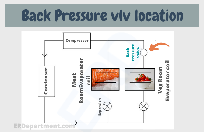
The Back Pressure Valve is a required accessory when pumping to a low pressure injection point below the tank level or when pumping from a bulk tank with a high head pressure.


 8613371530291