
bellows safety valve brands
Supplier of bellows seal valves. Types of bellows seal valves include valves with flanges, socket ends, butt weld ends, & long bellow butt weld ends. Specifications include nominal diameters ranging from 1/2 in. to 20 in., & 150 to 300 ANSI nominal pressure. Features of valves include straight-through & Y-pattern designs, chrome nickel steel bell with air cushion between bell & housing, chrome-nickel steel bellows, stainless steel stem, disk & seat, & disk flexibly attached to stem. Media includes steam, gases, hot water, thermal fluids, hot oil, process water, vacuum facilities, ammonia, process water, & aggressive media.
Distributor of bellow seal control valves & actuators, both 2-way & 3-way, for leak-free long life in high temperature service such as thermal oil & other high temperature liquid applications. Also manufactures ejector valves & actuators that provide loop temperature control without secondary circulation pumps, both 3-way & 4-way, for hot water & steam control systems. Steam systems include condensate & blow down waste heat recovery packages. Also distributes complete temperature control & automation skid packages for all control valves & associated control systems.
Distributor of bellows seals made from polyvinyl chloride (PVC), polyvinylidene fluoride (PVDF) and polypropylene. Various types include ethylene propylene diene monomer (EPDM) and KFM seal valves. Available in 1/4 to 2 in. sizes. Serves the refinery, mining, wastewater treatment and power production industries. Most items available in stock. 24/7, pump repair, export and material identification services provided. Same day shipping.
Distributor of valves including bellows seal and bleed valves. JIS, DIN, ANSI and butterfly valves are also available. Stock items are also available. Same day shipping.
Distributor of corrosion resistant and leak proof valves including bellow seal valves. Types include shutoff and control valves. Applications include industries, power stations, flue gas purification plants, gas supplies, processing technologies, vapor facilities, thermal oil applications, recycling facilities, vacuum facilities, ammonia, hot waters, heating technologies, cooling and freezing systems, general plant manufacturing and steam systems.
Distributor of valves including ball, socket and butt weld, metering, plug, poppet and threaded. Globe and gate valve are also available. Products range in size between 1/4 inch to 3 inches. Stainless and carbon steel valves available.
Distributor of valves. Check valves, solenoid valves, ball valves, cryogenic valves, relief valves, needle valves, plug valves, actuated valves, diaphragm valves, pressure regulators, cylinder regulators, back pressure regulators, control valves, & tube fittings. Markets served include industrial gas, chemical, medical, power, marine, oil & gas processing.
Stocking distributor of pipeline ancillaries including bellows sealed stop and check valves, manifolds and air vents. Ball, butterfly, gate, diaphragm and plug valves are also available.
Manufacturer of standard & custom bellows seal valves including direct acting normally-closed PTFE bellows seal solenoid valves for pressure, drain & vacuum service. Features include no metal parts in wetted area, rugged molded construction, resistant to atmospheric corrosion, molded corrosion-resistant coil assembly, IP-54/Nema 4 water & dust tight enclosure & optional coil connector light. Services include product innovation, engineering, precision manufacturing, pressure, flow & corrosion-resistant plastic piping, quality testing & technical assistance. RoHS compliant.
ISO 9001:2015 certified custom manufacturer of packless bellows seal valves made from stainless steel, brass and alloys. Types of bellows sealed valves include multi-valve manifold, manual, actuated, metering, secondary packed and high-pressure bellows valves. Features of bellows valves include 6 mm to 12.5 mm size, toggle operated, PCTFE stem tips, face seal rotatable threads and seal nuts, tube fittings, tube extensions, tube stubs, tube socket and butt-welding, NPT configurations and sample cylinders. ASME approved and METI/KHK, UNSPSC, eClass and TUV certified.
Stocking distributor of new, surplus industrial bellows seal valves and replacement parts from all major manufacturers. Other types include ball, butterfly, cartridge, check, control, pressure, hydraulic check, diaphragm, diverter, exhaust, gate and globe valves. Hydraulic, knife gate, needle, piston, plug, pneumatic, relief, rotary, thermostatic and wedge gate valves are also offered. Express and same-day shipping are available on most items. Asset recovery and consignment services are also available. Stock will vary.
Manufacturer and worldwide distributor of aluminum, stainless steel and mild steel vacuum valves. Gate, angle (poppet) and rectangular ports. ANSI, ISO, Conflat and JIS flanges are available.
Stocking distributor of bellows seal valves available in forged steel, cast steel, chrome molly, stainless steel, Monel®, Hastelloy® B & C, cast iron, ductile iron, bronze, brass & PVC. Electric, hydraulic & pneumatic actuations. Modifications include flange ups, conversions, coatings, hydro testing, packing changes & trim changes.
Stocking distributor of valves made from stainless steel, carbon steel, aluminum, bronze, and brass materials. Products include safety relief, shut down, knife gate, cryogenic, double block, and bleed valves. Globe, ball, butterfly, diaphragm, and choke valves are offered. Bonnet, check, foot, metering, and piggable valves are also available. Gauge, isolating, pilot, plug, regulator, pressure, and bellows seal valves are provided. Serves chemical processing, water, power generation, petroleum, utility, nuclear, marine, distillery, oil, and gas industries. Meets NACE standard.
Distributor of bellows seal valves. Offered in 1/4 in. to 1 in. size, temperature ranges from 70 degrees F to 800 degrees F and pressure ranges up to 1500 psi. Features includes interchangeable trim sets, Linear, equal percent, quick open or double taper, TFE CV ring backup packing and TFE bellows gasket. Calibration services are available. Applications include automotive aftermarket, commercial, irrigation, sustainability, aviation and aerospace, concrete finishing, oil, building automation/HVAC, concrete production, chemical, industrial, refining and petrochemical and water distribution.
Manufacturer of standard and custom bellows seal valves made from forged steel. Available in gate and globe design configurations. Features vary depending upon model and include male-female joints, spiral wound gaskets, ring joint gaskets, antic-static devices, anti-blow-out proof stems, optional locking devices and oval safety handles, seat rings, yoke sleeves and hand wheels. Serves oil and natural gas, nuclear power, chemical, refineries, petrochemical and piping plants industries. CE certified.
Distributor of bellow seal solenoid valves for industrial flow control applications. Available in 1/4 to 12 in. sizes. Made from PVC, PVDF and polypropylene with EPDM and FKM seals. Other types include ball, butterfly and diaphragm valves. Offers custom plastic fabrication services. Additional services such as repair and maintenance available. Serves refineries, mining, wastewater treatment and power production industries. Stock items available.
Manufacturer of bellow and pressure seal valves for pulp and paper, fossil power, refineries, water treatment and nuclear power industries. Available in 1/2 to 4 in. sizes. Made from carbon steel, Inconel®, cobalt alloy, steel and stainless steel. Valve designs include angle, Y and T-pattern. Other types include globe, gate, ball, pressure, check, blowdown, three-way, throttling, bypass and fire safety valves. Suitable for boilers, cryogenic and hydraulic systems, chemical plants, drains, vents, chemical fuel lines, compressors and turbine generators. Two year warranty available. Meets ASME and ASTM standards. Made in the USA.
Engineering of temperature, pressure & flow products including self-operated control valves for temperature regulation; steam tracing, freeze & scald protection, unit heated controls, heat exchange control, hot & cold water mixing. Also thermostatic steam traps including pinch traps, bi-metallic for pressures from 0 to 1200 psi.
Distributor of stainless steel bellows seal valves for fluid handling applications. Features include bellows subassemblies and secondary sealing systems. Suitable for use in cryogenic to high temperatures, and in vacuum to high pressure. Valves can be used in instrumentation, panel and critical sampling systems for toxic, radioactive and hazardous fluids. Specializes in servicing the oil and gas industry.
Distributor of bellows seal isolation valves for high pressure and high temperature applications. Inventory management programs available. Meets ASME, ANSI, ASTM and API standards.
Distributor of valves including actuated, automated or automatic, bellows seal, compressor and diverter valves. Capabilities include field repair, inspection, testing, CNC lathe work, fabrication, reverse engineering, machining, welding, re-surfacing, installation, calibration, maintenance, consulting, modification and polishing. Meets ASME standards. One year warranty.
Manufacturer of standard and custom valves. Gate, globe, ball, check, butterfly, control, plug and cryogenic valves are offered. Pressure reducing, bellows seal, knife gate, triple offset, safety, pneumatic and electrically operated valves are also available. Y strainers are provided. Serves mining, petrochemical, marine, energy, automobile, chemical, refinery, wastewater treatment, oil and gas industries.
130 Series Safety valves are also available as Relief valves. Relief valves, identified by the letter R after the type number, are devices with an operational function, ...
240 Series Safety valves are also available as Relief valves. Relief valves, identified by the letter R after the type number, are devices with an operational function, ...
250 Series Safety valves are also available as Relief valves. Relief valves, identified by the letter R after the type number, are devices with an operational function, ...
271 Series Safety valves are also available as Relief valves. Relief valves, identified by the letter R after the type number, are devices with an operational function ...
Relief Valves GLV-Series are spring loaded pressure relieving devices, suitable for discharge of incompressible fluids. GLV-series relief valves are used to protect personnel and equipment by preventing ...
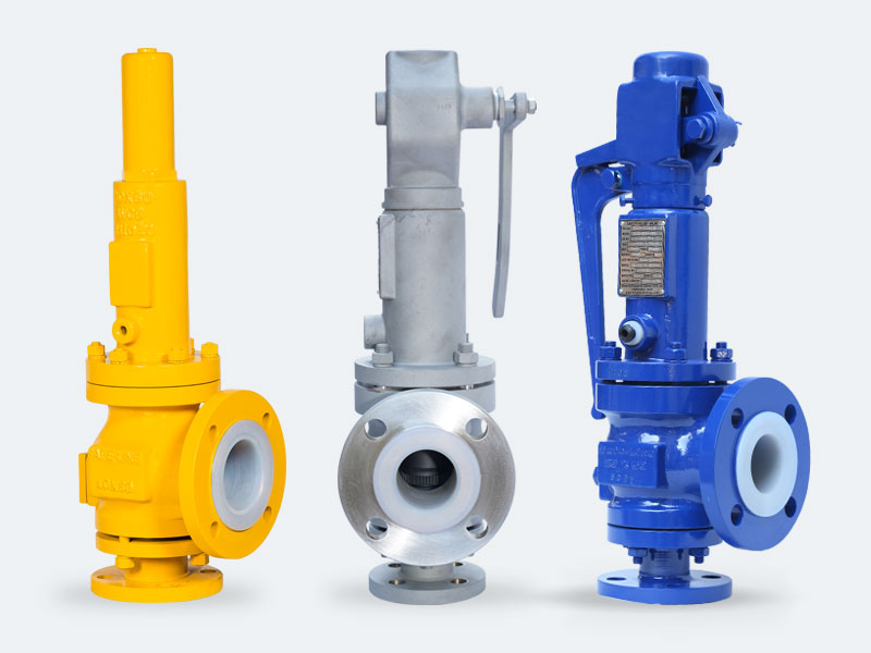
Our products are widely recognized and trusted by users and can meet continuously developing economic and social needs for Bellows Safety Valve, Filter, Flow Meters, Flange Type Valve,Pe Ball Valve. We are trying to get for in depth cooperation with sincere shoppers, attaining a new result in of glory with customers and strategic partners. The product will supply to all over the world, such as Europe, America, Australia,Sacramento, America,Wellington, Cancun.Products have been exported to Asia, Mid-east,European and Germany market. Our company has constantly been able to update the products performance and safety to meet the markets and strive to be top A on stable quality and sincere service. If you have the honor to do business with our company. we will definitely do our very best to support your business in China.
There is a wide range of safety valves available to meet the many different applications and performance criteria demanded by different industries. Furthermore, national standards define many varying types of safety valve.
The ASME standard I and ASME standard VIII for boiler and pressure vessel applications and the ASME/ANSI PTC 25.3 standard for safety valves and relief valves provide the following definition. These standards set performance characteristics as well as defining the different types of safety valves that are used:
ASME I valve - A safety relief valve conforming to the requirements of Section I of the ASME pressure vessel code for boiler applications which will open within 3% overpressure and close within 4%. It will usually feature two blowdown rings, and is identified by a National Board ‘V’ stamp.
ASME VIII valve- A safety relief valve conforming to the requirements of Section VIII of the ASME pressure vessel code for pressure vessel applications which will open within 10% overpressure and close within 7%. Identified by a National Board ‘UV’ stamp.
Full bore safety valve - A safety valve having no protrusions in the bore, and wherein the valve lifts to an extent sufficient for the minimum area at any section, at or below the seat, to become the controlling orifice.
Conventional safety relief valve -The spring housing is vented to the discharge side, hence operational characteristics are directly affected by changes in the backpressure to the valve.
Balanced safety relief valve -A balanced valve incorporates a means of minimising the effect of backpressure on the operational characteristics of the valve.
Pilot operated pressure relief valve -The major relieving device is combined with, and is controlled by, a self-actuated auxiliary pressure relief device.
Power-actuated safety relief valve - A pressure relief valve in which the major pressure relieving device is combined with, and controlled by, a device requiring an external source of energy.
Standard safety valve - A valve which, following opening, reaches the degree of lift necessary for the mass flowrate to be discharged within a pressure rise of not more than 10%. (The valve is characterised by a pop type action and is sometimes known as high lift).
Full lift (Vollhub) safety valve -A safety valve which, after commencement of lift, opens rapidly within a 5% pressure rise up to the full lift as limited by the design. The amount of lift up to the rapid opening (proportional range) shall not be more than 20%.
Direct loaded safety valve -A safety valve in which the opening force underneath the valve disc is opposed by a closing force such as a spring or a weight.
Proportional safety valve - A safety valve which opens more or less steadily in relation to the increase in pressure. Sudden opening within a 10% lift range will not occur without pressure increase. Following opening within a pressure of not more than 10%, these safety valves achieve the lift necessary for the mass flow to be discharged.
Diaphragm safety valve -A direct loaded safety valve wherein linear moving and rotating elements and springs are protected against the effects of the fluid by a diaphragm
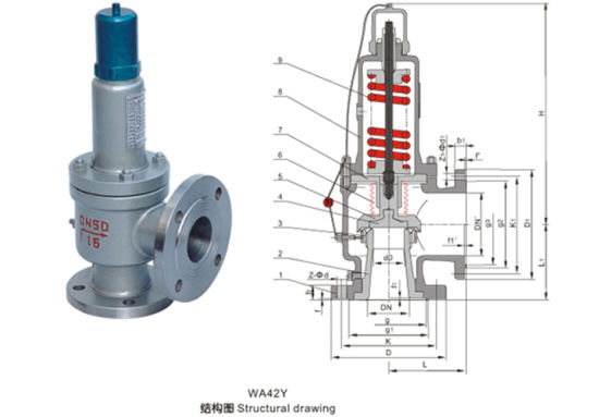
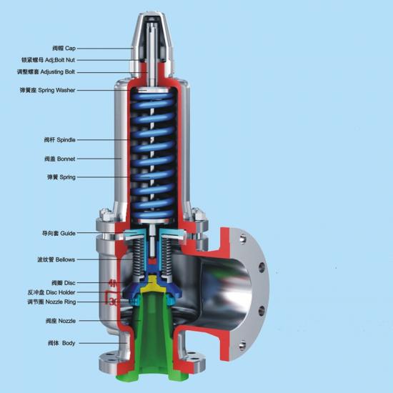
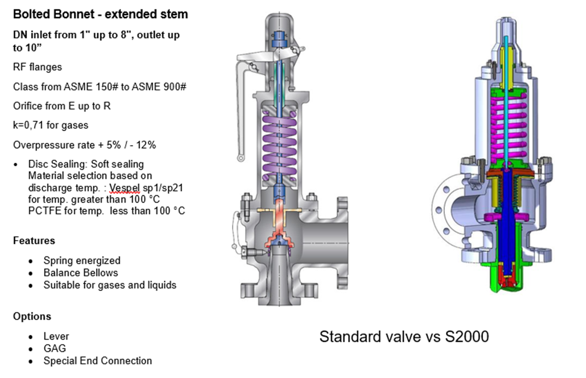
Bellows safety valve - A direct loaded safety valve wherein sliding and (partially or fully) rotating elements and springs are protected against the effects of the fluids by a bellows. The bellows may be of such a design that it compensates for influences of backpressure.
Controlled safety valve - Consists of a main valve and a control device. It also includes direct acting safety valves with supplementary loading in which, until the set pressure is reached, an additional force increases the closing force.
Safety valve - A safety valve which automatically, without the assistance of any energy other than that of the fluid concerned, discharges a quantity of the fluid so as to prevent a predetermined safe pressure being exceeded, and which is designed to re-close and prevent further flow of fluid after normal pressure conditions of service have been restored. Note; the valve can be characterised either by pop action (rapid opening) or by opening in proportion (not necessarily linear) to the increase in pressure over the set pressure.
Direct loaded safety valve -A safety valve in which the loading due to the fluid pressure underneath the valve disc is opposed only by a direct mechanical loading device such as a weight, lever and weight, or a spring.
Assisted safety valve -A safety valve which by means of a powered assistance mechanism, may additionally be lifted at a pressure lower than the set pressure and will, even in the event of a failure of the assistance mechanism, comply with all the requirements for safety valves given in the standard.
Supplementary loaded safety valve - A safety valve that has, until the pressure at the inlet to the safety valve reaches the set pressure, an additional force, which increases the sealing force.
Note; this additional force (supplementary load), which may be provided by means of an extraneous power source, is reliably released when the pressure at the inlet of the safety valve reaches the set pressure. The amount of supplementary loading is so arranged that if such supplementary loading is not released, the safety valve will attain its certified discharge capacity at a pressure not greater than 1.1 times the maximum allowable pressure of the equipment to be protected.
Pilot operated safety valve -A safety valve, the operation of which is initiated and controlled by the fluid discharged from a pilot valve, which is itself, a direct loaded safety valve subject to the requirement of the standard.
The common characteristic shared between the definitions of conventional safety valves in the different standards, is that their operational characteristics are affected by any backpressure in the discharge system. It is important to note that the total backpressure is generated from two components; superimposed backpressure and the built-up backpressure:
Subsequently, in a conventional safety valve, only the superimposed backpressure will affect the opening characteristic and set value, but the combined backpressure will alter the blowdown characteristic and re-seat value.
The ASME/ANSI standard makes the further classification that conventional valves have a spring housing that is vented to the discharge side of the valve. If the spring housing is vented to the atmosphere, any superimposed backpressure will still affect the operational characteristics. Thiscan be seen from Figure 9.2.1, which shows schematic diagrams of valves whose spring housings are vented to the discharge side of the valve and to the atmosphere.
By considering the forces acting on the disc (with area AD), it can be seen that the required opening force (equivalent to the product of inlet pressure (PV) and the nozzle area (AN)) is the sum of the spring force (FS) and the force due to the backpressure (PB) acting on the top and bottom of the disc. In the case of a spring housing vented to the discharge side of the valve (an ASME conventional safety relief valve, see Figure 9.2.1 (a)), the required opening force is:
In both cases, if a significant superimposed backpressure exists, its effects on the set pressure need to be considered when designing a safety valve system.
Once the valve starts to open, the effects of built-up backpressure also have to be taken into account. For a conventional safety valve with the spring housing vented to the discharge side of the valve, see Figure 9.2.1 (a), the effect of built-up backpressure can be determined by considering Equation 9.2.1 and by noting that once the valve starts to open, the inlet pressure is the sum of the set pressure, PS, and the overpressure, PO.
Balanced safety valves are those that incorporate a means of eliminating the effects of backpressure. There are two basic designs that can be used to achieve this:
Although there are several variations of the piston valve, they generally consist of a piston type disc whose movement is constrained by a vented guide. The area of the top face of the piston, AP, and the nozzle seat area, AN, are designed to be equal. This means that the effective area of both the top and bottom surfaces of the disc exposed to the backpressure are equal, and therefore any additional forces are balanced. In addition, the spring bonnet is vented such that the top face of the piston is subjected to atmospheric pressure, as shown in Figure 9.2.2.
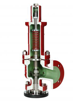
The bellows arrangement prevents backpressure acting on the upper side of the disc within the area of the bellows. The disc area extending beyond the bellows and the opposing disc area are equal, and so the forces acting on the disc are balanced, and the backpressure has little effect on the valve opening pressure.
Bellows failure is an important concern when using a bellows balanced safety valve, as this may affect the set pressure and capacity of the valve. It is important, therefore, that there is some mechanism for detecting any uncharacteristic fluid flow through the bellows vents. In addition, some bellows balanced safety valves include an auxiliary piston that is used to overcome the effects of backpressure in the case of bellows failure. This type of safety valve is usually only used on critical applications in the oil and petrochemical industries.
In addition to reducing the effects of backpressure, the bellows also serve to isolate the spindle guide and the spring from the process fluid, this is important when the fluid is corrosive.
Since balanced pressure relief valves are typically more expensive than their unbalanced counterparts, they are commonly only used where high pressure manifolds are unavoidable, or in critical applications where a very precise set pressure or blowdown is required.
This type of safety valve uses the flowing medium itself, through a pilot valve, to apply the closing force on the safety valve disc. The pilot valve is itself a small safety valve.
The diaphragm type is typically only available for low pressure applications and it produces a proportional type action, characteristic of relief valves used in liquid systems. They are therefore of little use in steam systems, consequently, they will not be considered in this text.
The piston type valve consists of a main valve, which uses a piston shaped closing device (or obturator), and an external pilot valve. Figure 9.2.4 shows a diagram of a typical piston type, pilot operated safety valve.
The piston and seating arrangement incorporated in the main valve is designed so that the bottom area of the piston, exposed to the inlet fluid, is less than the area of the top of the piston. As both ends of the piston are exposed to the fluid at the same pressure, this means that under normal system operating conditions, the closing force, resulting from the larger top area, is greater than the inlet force. The resultant downward force therefore holds the piston firmly on its seat.
If the inlet pressure were to rise, the net closing force on the piston also increases, ensuring that a tight shut-off is continually maintained. However, when the inlet pressure reaches the set pressure, the pilot valve will pop open to release the fluid pressure above the piston. With much less fluid pressure acting on the upper surface of the piston, the inlet pressure generates a net upwards force and the piston will leave its seat. This causes the main valve to pop open, allowing the process fluid to be discharged.
When the inlet pressure has been sufficiently reduced, the pilot valve will reclose, preventing the further release of fluid from the top of the piston, thereby re-establishing the net downward force, and causing the piston to reseat.
Pilot operated safety valves offer good overpressure and blowdown performance (a blowdown of 2% is attainable). For this reason, they are used where a narrow margin is required between the set pressure and the system operating pressure. Pilot operated valves are also available in much larger sizes, making them the preferred type of safety valve for larger capacities.
One of the main concerns with pilot operated safety valves is that the small bore, pilot connecting pipes are susceptible to blockage by foreign matter, or due to the collection of condensate in these pipes. This can lead to the failure of the valve, either in the open or closed position, depending on where the blockage occurs.
The terms full lift, high lift and low lift refer to the amount of travel the disc undergoes as it moves from its closed position to the position required to produce the certified discharge capacity, and how this affects the discharge capacity of the valve.
A full lift safety valve is one in which the disc lifts sufficiently, so that the curtain area no longer influences the discharge area. The discharge area, and therefore the capacity of the valve are subsequently determined by the bore area. This occurs when the disc lifts a distance of at least a quarter of the bore diameter. A full lift conventional safety valve is often the best choice for general steam applications.
The disc of a high lift safety valve lifts a distance of at least 1/12th of the bore diameter. This means that the curtain area, and ultimately the position of the disc, determines the discharge area. The discharge capacities of high lift valves tend to be significantly lower than those of full lift valves, and for a given discharge capacity, it is usually possible to select a full lift valve that has a nominal size several times smaller than a corresponding high lift valve, which usually incurs cost advantages.Furthermore, high lift valves tend to be used on compressible fluids where their action is more proportional.
In low lift valves, the disc only lifts a distance of 1/24th of the bore diameter. The discharge area is determined entirely by the position of the disc, and since the disc only lifts a small amount, the capacities tend to be much lower than those of full or high lift valves.
Except when safety valves are discharging, the only parts that are wetted by the process fluid are the inlet tract (nozzle) and the disc. Since safety valves operate infrequently under normal conditions, all other components can be manufactured from standard materials for most applications. There are however several exceptions, in which case, special materials have to be used, these include:
Cast steel -Commonly used on higher pressure valves (up to 40 bar g). Process type valves are usually made from a cast steel body with an austenitic full nozzle type construction.
For all safety valves, it is important that moving parts, particularly the spindle and guides are made from materials that will not easily degrade or corrode. As seats and discs are constantly in contact with the process fluid, they must be able to resist the effects of erosion and corrosion.
The spring is a critical element of the safety valve and must provide reliable performance within the required parameters. Standard safety valves will typically use carbon steel for moderate temperatures. Tungsten steel is used for higher temperature, non-corrosive applications, and stainless steel is used for corrosive or clean steam duty. For sour gas and high temperature applications, often special materials such as monel, hastelloy and ‘inconel’ are used.
Standard safety valves are generally fitted with an easing lever, which enables the valve to be lifted manually in order to ensure that it is operational at pressures in excess of 75% of set pressure. This is usually done as part of routine safety checks, or during maintenance to prevent seizing. The fitting of a lever is usually a requirement of national standards and insurance companies for steam and hot water applications. For example, the ASME Boiler and Pressure Vessel Code states that pressure relief valves must be fitted with a lever if they are to be used on air, water over 60°C, and steam.
A test gag (Figure 9.2.7) may be used to prevent the valve from opening at the set pressure during hydraulic testing when commissioning a system. Once tested, the gag screw is removed and replaced with a short blanking plug before the valve is placed in service.
The amount of fluid depends on the particular design of safety valve. If emission of this fluid into the atmosphere is acceptable, the spring housing may be vented to the atmosphere – an open bonnet. This is usually advantageous when the safety valve is used on high temperature fluids or for boiler applications as, otherwise, high temperatures can relax the spring, altering the set pressure of the valve. However, using an open bonnet exposes the valve spring and internals to environmental conditions, which can lead to damage and corrosion of the spring.
When the fluid must be completely contained by the safety valve (and the discharge system), it is necessary to use a closed bonnet, which is not vented to the atmosphere. This type of spring enclosure is almost universally used for small screwed valves and, it is becoming increasingly common on many valve ranges since, particularly on steam, discharge of the fluid could be hazardous to personnel.
Some safety valves, most commonly those used for water applications, incorporate a flexible diaphragm or bellows to isolate the safety valve spring and upper chamber from the process fluid, (see Figure 9.2.9).
An elastomer bellows or diaphragm is commonly used in hot water or heating applications, whereas a stainless steel one would be used on process applications employing hazardous fluids.
The highly adaptable 1900 Series Safety Relief Valve with the Eductor Tube Advantage is designed to meet a wide range of industrial applications and is certified for gas, liquid and steam media in conventional and balanced bellows designs. The 1900 Series design flexibility and parts interchangeability accommodate process changes through easy conversion to a variety of designs.
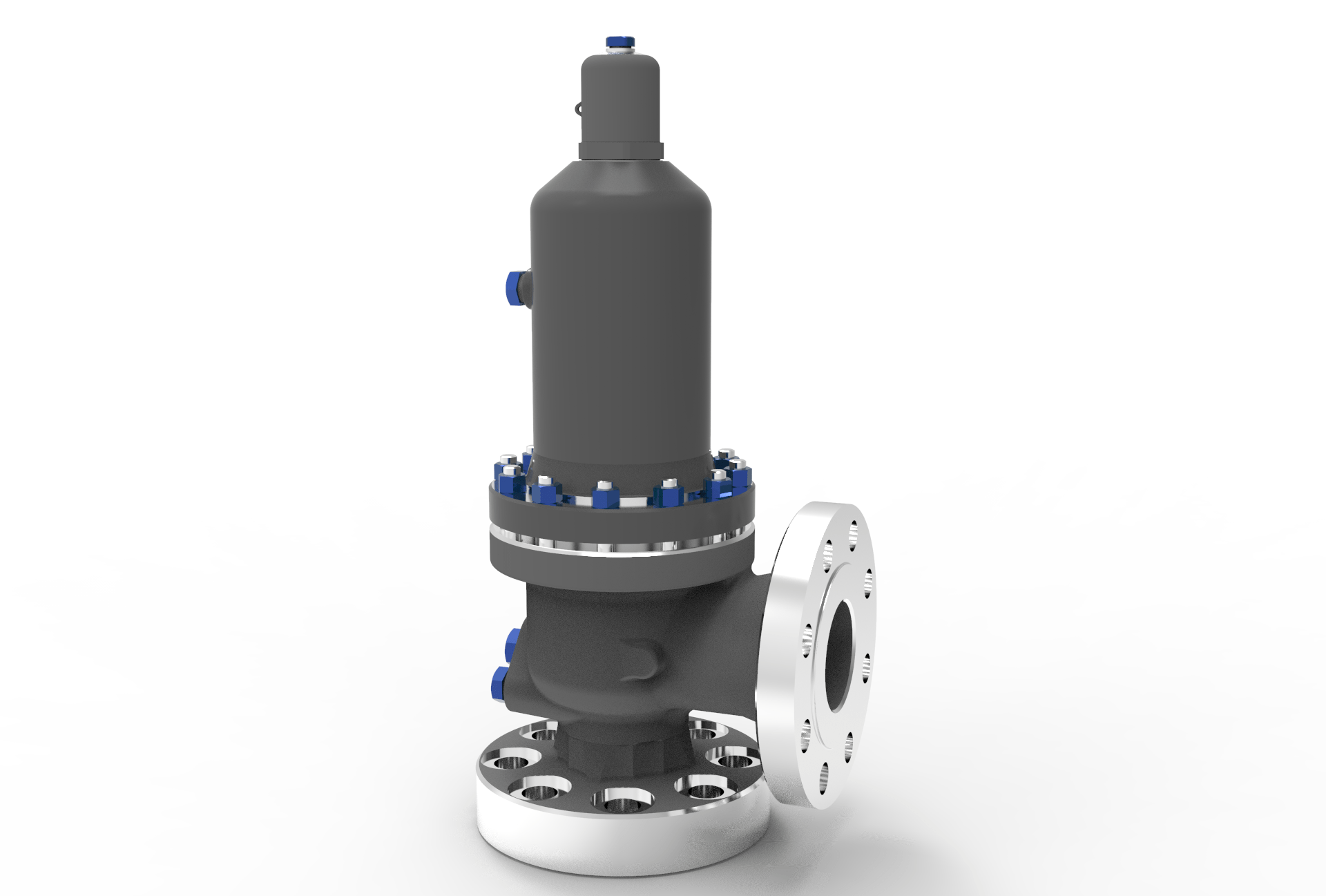
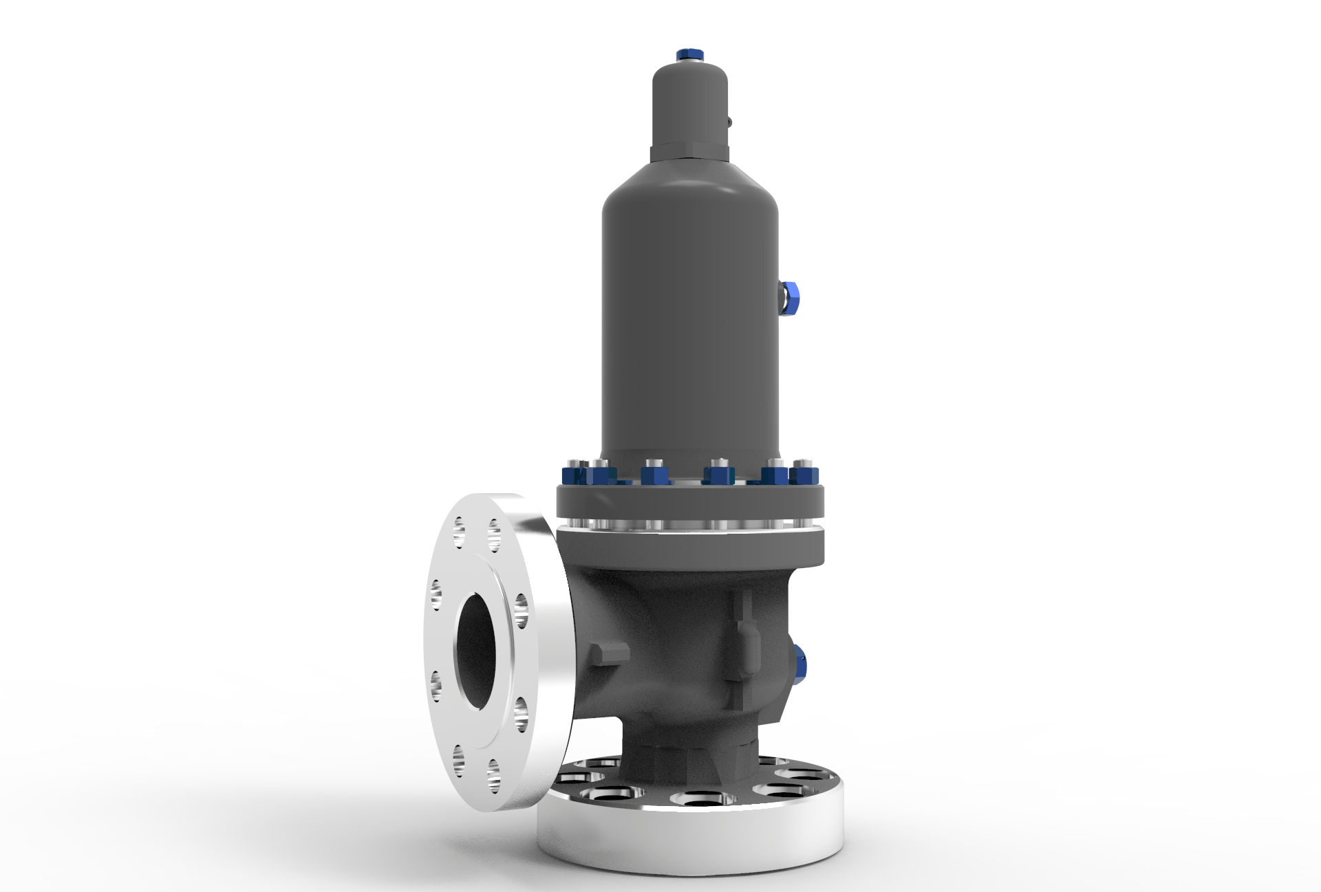
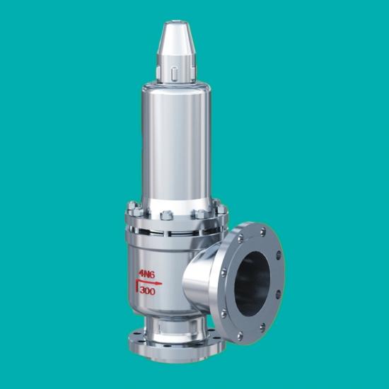
Bellow balanced safety valves are designed to reduce the effetc of back pressure accumulation, the "Bellows" located between the bonnet and the valve body, where maintained free from the effetc of back pressure, the opposing pressure on the inlet fluid is only generated by the spring without contribution from any sort of backpressure. The space enclosed by bellows is freely vented to air, the back pressure is expetced to be 10 - 50% of the set pressure. The Bellows can also protetc the spring and other trim components from corrosive media.

API 520 Bellow Balanced Safety Valve Manufacturer: API 520 Balanced Bellows Safety Valve with Flange, Inlet Class 900, Outlet Class 300 LB, 3 X 4 Inch.
Bonnet: The bonnet of the safety valve is open, allowing the spring chamber to communicate with the atmosphere, which is beneficial to reduce the temperature of the spring, and is mainly suitable for containers of high temperature gas in which the medium is steam and does not pollute the atmosphere.
Lever: The safety valve can be opened manually by the lever when the media pressure over 75% of the setting pressure (On the premise of ensuring safety).
The Sarasin-RSBD® 9 Series is a compact Spring Loaded Pressure Relief Valve offering a versatile design with premium performance. The Sarasin-RSBD® 9 Series range of Spring Loaded Pressure Relief Valves are available in both conventional and balanced bellows designs. These compact spring loaded safety relief valves can be used in vapor, gas, liquid, or steam applications.
The Sarasin-RSBD® safety relief valves are designed to provide high integrity performance and repeatability by their use of an integral full, one-piece nozzle, a self-aligning top-guided disc & disc-holder, and a single adjusting ring for blowdown setting. The 9 Series pressure relief valves are suitable for use within the power industry as well as for cryogenic and industrial gas processes.
Curtiss-Wright"s selection of Pressure Relief Valves comes from its outstanding product brands Farris and Target Rock. We endeavor to support the whole life cycle of a facility and continuously provide custom products and technologies. Boasting a reputation for producing high quality, durable products, our collection of Pressure Relief Valves is guaranteed to provide effective and reliable pressure relief.
While some basic components and activations in relieving pressure may differ between the specific types of relief valves, each aims to be 100% effective in keeping your equipment running safely. Our current range includes numerous valve types, from flanged to spring-loaded, threaded to wireless, pilot operated, and much more.
A pressure relief valve is a type of safety valve designed to control the pressure in a vessel. It protects the system and keeps the people operating the device safely in an overpressure event or equipment failure.
A pressure relief valve is designed to withstand a maximum allowable working pressure (MAWP). Once an overpressure event occurs in the system, the pressure relief valve detects pressure beyond its design"s specified capability. The pressure relief valve would then discharge the pressurized fluid or gas to flow from an auxiliary passage out of the system.
Below is an example of one of our pilot operated pressure relief valves in action; the cutaway demonstrates when high pressure is released from the system.
Air pressure relief valves can be applied to a variety of environments and equipment. Pressure relief valves are a safety valve used to keep equipment and the operators safe too. They"re instrumental in applications where proper pressure levels are vital for correct and safe operation. Such as oil and gas, power generation like central heating systems, and multi-phase applications in refining and chemical processing.
At Curtiss-Wright, we provide a range of different pressure relief valves based on two primary operations – spring-loaded and pilot operated. Spring-loaded valves can either be conventional spring-loaded or balanced spring-loaded.
Spring-loaded valves are programmed to open and close via a spring mechanism. They open when the pressure reaches an unacceptable level to release the material inside the vessel. It closes automatically when the pressure is released, and it returns to an average operating level. Spring-loaded safety valves rely on the closing force applied by a spring onto the main seating area. They can also be controlled in numerous ways, such as a remote, control panel, and computer program.
Pilot-operated relief valves operate by combining the primary relieving device (main valve) with self-actuated auxiliary pressure relief valves, also known as the pilot control. This pilot control dictates the opening and closing of the main valve and responds to system pressure. System pressure is fed from the inlet into and through the pilot control and ultimately into the main valve"s dome. In normal operating conditions, system pressure will prevent the main valve from opening.
The valves allow media to flow from an auxiliary passage and out of the system once absolute pressure is reached, whether it is a maximum or minimum level.
When the pressure is below the maximum amount, the pressure differential is slightly positive on the piston"s dome size, which keeps the main valve in the closed position. When system pressure rises and reaches the set point, the pilot will cut off flow to the dome, causing depressurization in the piston"s dome side. The pressure differential has reversed, and the piston will rise, opening the main valve, relieving pressure.
When the process pressure decreases to a specific pressure, the pilot closes, the dome is repressurized, and the main valve closes. The main difference between spring-loaded PRVs and pilot-operated is that a pilot-operated safety valve uses pressure to keep the valve closed.
Pilot-operated relief valves are controlled by hand and are typically opened often through a wheel or similar component. The user opens the valve when the gauge signifies that the system pressure is at an unsafe level; once the valve has opened and the pressure has been released, the operator can shut it by hand again.
Increasing pressure helps to maintain the pilot"s seal. Once the setpoint has been reached, the valve opens. This reduces leakage and fugitive emissions.
At set pressure the valve snaps to full lift. This can be quite violent on large pipes with significant pressure. The pressure has to drop below the set pressure in order for the piston to reseat.
At Curtiss-Wright we also provide solutions for pressure relief valve monitoring. Historically, pressure relief valves have been difficult or impossible to monitor. Our SmartPRV features a 2600 Series pressure relief valve accessorized with a wireless position monitor that alerts plant operators during an overpressure event, including the time and duration.
There are many causes of overpressure, but the most common ones are typically blocked discharge in the system, gas blowby, and fire. Even proper inspection and maintenance will not eliminate the occurrence of leakages. An air pressure relief valve is the only way to ensure a safe environment for the device, its surroundings, and operators.
A PRV and PSV are interchangeable, but there is a difference between the two valves. A pressure release valve gradually opens when experiencing pressure, whereas a pressure safety valve opens suddenly when the pressure hits a certain level of over pressurization. Safety valves can be used manually and are typically used for a permanent shutdown. Air pressure relief valves are used for operational requirements, and they gently release the pressure before it hits the maximum high-pressure point and circulates it back into the system.
Pressure relief valves should be subject to an annual test, one per year. The operator is responsible for carrying out the test, which should be done using an air compressor. It’s imperative to ensure pressure relief valves maintain their effectiveness over time and are checked for signs of corrosion and loss of functionality. Air pressure relief valves should also be checked before their installation, after each fire event, and regularly as decided by the operators.
Direct-acting solenoid valves have a direct connection with the opening and closing armature, whereas pilot-operated valves use of the process fluid to assist in piloting the operation of the valve.
A control valve works by varying the rate of fluid passing through the valve itself. As the valve stem moves, it alters the size of the passage and increases, decreases or holds steady the flow. The opening and closing of the valve is altered whenever the controlled process parameter does not reach the set point.
Control valves are usually at floor level or easily accessible via platforms. They are also located on the same equipment or pipeline as the measurement and downstream or flow measurements.
An industrial relief valve is designed to control or limit surges of pressure in a system, most often in fluid or compressed air system valves. It does so as a form of protection for the system and defending against instrument or equipment failure. They are usually present in clean water industries.
A PRV is often referred to as a pressure relief valve, which is also known as a PSV or pressure safety valve. They are used interchangeably throughout the industry depending on company standards.


 8613371530291