
blowdown pressure of safety valve quotation
Providing you the best range of stainless steel water pressure relief valves, safety and pressure relief valves, flanged safety relief valve, industrial safety relief valves, pressure safety relief valves and cast steel safety relief valves with effective & timely delivery.

WARNING: Some of the products we sell can expose you to chemicals known to the State of California to cause cancer, birth defects or other reproductive harm. Contact your sales rep or go to www.P65Warnings.ca.gov for more information.
(PowersTM, also known as, POWERS REGULATOR, MCC POWERS, POWERS-FIAT, POWERS PROCESS CONTROLS, CRANE POWERS and POWERS, a Watts Industries Company. The POWERS trademark is owned by Powers, A Division of Watts Water Technologies, Inc. M&M Control Service, Inc. Is a Stocking Distributor for PowersTM)
Everlasting lever operated quick-opening, lever and gear operated, angle pattern blow-off valve with a 1-1/2" flanged connection with a maximum steam service of 250 psi. Learn More

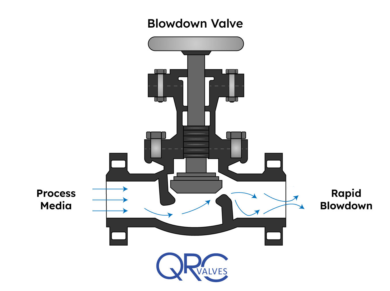
A blowdown valve’s main function is to control a continuous or intermittent flow of steam or fluid under high differential pressure. When installed in a system, they drain solid contaminants from the fluid. In this article, you will learn the working principle of a blowdown valve, review a blowdown valve diagram, and its use in boiler and compressor applications.
In industry, blowdown valves often attach to equipment where water is the working fluid. Usually, this water contains suspended solid impurities. As mechanisms such as vaporization or drafting occur in the system, the concentration of undissolved solids increases and hampers system performance. How? Some of these deposits may accumulate and form blockages that disrupt the flow. Also, the solids could deposit on the surface of the equipment and impact heat transfer. This reduces the efficiency of heat exchangers and designed cooling measures. Thus, blowdown valves along drain lines allow for the removal of these contaminants.
It is a common practice to use two blowdown valves in series. One acts as the seal valve, while the other is the main blowdown valve. Customarily, the seal valve opens first when draining, and closes last. However, to minimize erosion of the valve disk faces and seats, both may open simultaneously and rapidly.
In addition, care should be taken to avoid trapping scale and rust particles within the valve by briefly reopening it, after it has been shut. Especially if there was resistance when closing it initially. One important parameter in the operation of blowdown valves is the blowdown percentage. It refers to the ratio of the quantity of blowdown water (Vblowdown) to that of the feedwater (Vfeed) as the formula below shows.
For most applications, the blowdown percentage lies between 4% to 10%. However, it could be as low as 1% when the system has access to high-quality feedwater. On the other hand, it could reach above 20% in a critical system with poor quality feedwater. In any case, caution should be exercised to evacuate as many contaminants as possible, but without emptying the equipment.
The classification of blowdown valves depends on either the valve location or working interval. Generally, blowdown valves are installed at the surface or the bottom of the equipment, depending on the speed of solid impurities precipitation. Also, the valve may operate continuously or intermittently. Usually, surface blowdown valves operate in steady state, while bottom blowdown valves work intermittently.
This is suitable for applications where the rate of solid impurities precipitation is relatively slower. For a simple design of this type of valve, a pipe inserts near the surface of the water level. Then, water, along with impurities, goes through the pipe continuously as the valve is normally in the open position.
On the other hand, a more sophisticated design uses a swivel joint with a short length of pipe suspended on a float. Thus, it removes oil floating on the water surface. Typically, surface blowdown valves find use in equipment where a significant amount of vaporization exists. This is because as vaporization occurs, the contaminants, precipitate and remain on the water surface. Also, the outlet of these valves often feeds into a flash tank and provides heating for heat exchangers.
As the name implies, this type of blowdown valves installs at the bottom of the equipment. They are opened periodically to enable the evacuation of accumulated solid impurities and sludge. Unlike the surface blowdown valve, this type does not operate in a steady state. This is because prolonged opening decreases the water level quickly, thereby risking a shutdown of the equipment. A basic requirement of this valve is to provide tight shut-off even after repetitive blowdown operations. Also, the drainpipe diameter should be large enough so that the slug does not clog and block the flow.
The diagram above is that of a manually operated blowdown valve. Of importance, the orifice maintains fluid velocity below levels that could damage the trim. Also, the stem mates to the orifice for proper control, while the open yoke enables the operator to see the position of the plunger in the valve body. A long stroke length of the stem enables the prevention of water hammer, which occurs if the valve is opened or closed too quickly. At the exit, the angle of the orifice is intentionally made divergent, to minimize downstream piping erosion and noise.
Blowdown valves are common in boiler and compressor systems. In compressors, they serve to depressurize the gas in the system at critical times such as shutdown, restart, or in the case of an emergency. In boilers, they see more frequent use, where there could be both bottom blowdown valves, and a surface valve, in some cases.
Generally, in boilers, blowdown valves remove both suspended solids and sludge from the surface and bottom respectively. As a result, it prevents the foaming at the water surface which leads to unstable water levels and excessive passing on of liquid in the steam. When blowdown water leaves a boiler, it does so at high temperatures, creating a safety concern. For example, a boiler working at 100 psig typically discharges around 338 ℉. Thus, engineers must ensure controlled discharge occurs into a flash tank prior to disposal into drainage. Or, engineers may repurpose the heat elsewhere within the facility, perhaps to increase feedwater temperature.
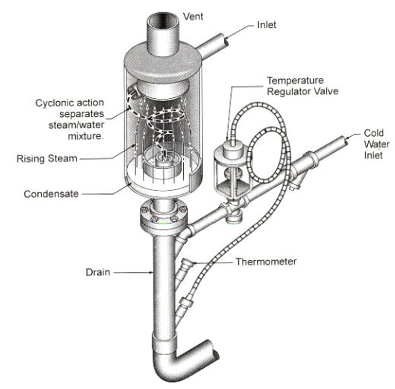
In some cases, having just the flash tank is not enough. Especially if the blowdown will end up in a sewer system. Environmental regulations require that water comes into sewers at 140 ℉ or less. As a result, such facilities use a blowdown separator to separate steam from the liquid, and further cool down the temperature, as seen in the apparatus below.

Relief and safety Valves are used in high pressure systems to control the pressure and keep balance of the system. The different between safety valves and relief valves is that the safety valves fully open or close under a certain pressure while the relief valves can open in proportion to the pressure in front of them. The safety and pressure relief valves are used automatically. They both operate under similar conditions. When the pressure builds up in a system, it has to be managed by releasing the material to flow through. These valves have a threshold pressure at which they open. The consolidated safety and safety relief valves comprise of a bonnet vent and bellow with springs.
The springs are set up for the threshold pressure and when the pressure exceeds the threshold, the spring is pushed into the bonnet vent and the bellow opens the valve. The Safety Relief Valves can be open and shut valves. They either open or shut off at any given pressure. This is mostly for the safety of an application not to explode under high pressure. The Pressure Relief Valve on the other hand releases the material after the threshold pressure, but not fully. If the pressure is slightly higher the threshold, then the valve opens slightly. If the pressure is very high above the threshold, it opens wider. It also functions in the same manner when the pressure drops down. The valve closes in proportion to the pressure. The safety valve shuts down at once only when the pressure is below the threshold.
Ready Stock of ASTM A351 CF8M Spring Loaded Safety Valve in wide range of Sizes, Stainless Steel Air Compressor Pressure Relief Valve Manufacturers In India
Relief Valves are designed to control pressure in a system While Safety Valves are used for controlling the pressure in a system they release pressure immediately in the event of an emergency or system failure
The Setpoint of relief valve is usually set at 10 Percent above working pressure limit while safety valve is usually set at 3% above working pressure limit.
If you are operating systems that can only be off for short periods of time, it is sensible to keep a spare valve to swap over and then the removed valve can be inspected and recertified.
Safety Relief ValvePioneers in the industry, we offer safety relief valve, pressure safety valve, thermal relief valve, sanitary safety valve, flange end safety relief valve and high pressure relief valve from India.

In order to ensure that the maximum allowable accumulation pressure of any system or apparatus protected by a safety valve is never exceeded, careful consideration of the safety valve’s position in the system has to be made. As there is such a wide range of applications, there is no absolute rule as to where the valve should be positioned and therefore, every application needs to be treated separately.
A common steam application for a safety valve is to protect process equipment supplied from a pressure reducing station. Two possible arrangements are shown in Figure 9.3.3.
The safety valve can be fitted within the pressure reducing station itself, that is, before the downstream stop valve, as in Figure 9.3.3 (a), or further downstream, nearer the apparatus as in Figure 9.3.3 (b). Fitting the safety valve before the downstream stop valve has the following advantages:
• The safety valve can be tested in-line by shutting down the downstream stop valve without the chance of downstream apparatus being over pressurised, should the safety valve fail under test.
• When setting the PRV under no-load conditions, the operation of the safety valve can be observed, as this condition is most likely to cause ‘simmer’. If this should occur, the PRV pressure can be adjusted to below the safety valve reseat pressure.
• Any additional take-offs downstream are inherently protected. Only apparatus with a lower MAWP requires additional protection. This can have significant cost benefits.
Indeed, a separate safety valve may have to be fitted on the inlet to each downstream piece of apparatus, when the PRV supplies several such pieces of apparatus.
• If supplying one piece of apparatus, which has a MAWP pressure less than the PRV supply pressure, the apparatus must be fitted with a safety valve, preferably close-coupled to its steam inlet connection.
• If a PRV is supplying more than one apparatus and the MAWP of any item is less than the PRV supply pressure, either the PRV station must be fitted with a safety valve set at the lowest possible MAWP of the connected apparatus, or each item of affected apparatus must be fitted with a safety valve.
• The safety valve must be located so that the pressure cannot accumulate in the apparatus viaanother route, for example, from a separate steam line or a bypass line.
It could be argued that every installation deserves special consideration when it comes to safety, but the following applications and situations are a little unusual and worth considering:
• Fire - Any pressure vessel should be protected from overpressure in the event of fire. Although a safety valve mounted for operational protection may also offer protection under fire conditions,such cases require special consideration, which is beyond the scope of this text.
• Exothermic applications - These must be fitted with a safety valve close-coupled to the apparatus steam inlet or the body direct. No alternative applies.
• Safety valves used as warning devices - Sometimes, safety valves are fitted to systems as warning devices. They are not required to relieve fault loads but to warn of pressures increasing above normal working pressures for operational reasons only. In these instances, safety valves are set at the warning pressure and only need to be of minimum size. If there is any danger of systems fitted with such a safety valve exceeding their maximum allowable working pressure, they must be protected by additional safety valves in the usual way.
In order to illustrate the importance of the positioning of a safety valve, consider an automatic pump trap (see Block 14) used to remove condensate from a heating vessel. The automatic pump trap (APT), incorporates a mechanical type pump, which uses the motive force of steam to pump the condensate through the return system. The position of the safety valve will depend on the MAWP of the APT and its required motive inlet pressure.
This arrangement is suitable if the pump-trap motive pressure is less than 1.6 bar g (safety valve set pressure of 2 bar g less 0.3 bar blowdown and a 0.1 bar shut-off margin). Since the MAWP of both the APT and the vessel are greater than the safety valve set pressure, a single safety valve would provide suitable protection for the system.
However, if the pump-trap motive pressure had to be greater than 1.6 bar g, the APT supply would have to be taken from the high pressure side of the PRV, and reduced to a more appropriate pressure, but still less than the 4.5 bar g MAWP of the APT. The arrangement shown in Figure 9.3.5 would be suitable in this situation.
Here, two separate PRV stations are used each with its own safety valve. If the APT internals failed and steam at 4 bar g passed through the APT and into the vessel, safety valve ‘A’ would relieve this pressure and protect the vessel. Safety valve ‘B’ would not lift as the pressure in the APT is still acceptable and below its set pressure.
It should be noted that safety valve ‘A’ is positioned on the downstream side of the temperature control valve; this is done for both safety and operational reasons:
Operation - There is less chance of safety valve ‘A’ simmering during operation in this position,as the pressure is typically lower after the control valve than before it.
Also, note that if the MAWP of the pump-trap were greater than the pressure upstream of PRV ‘A’, it would be permissible to omit safety valve ‘B’ from the system, but safety valve ‘A’ must be sized to take into account the total fault flow through PRV ‘B’ as well as through PRV ‘A’.
A pharmaceutical factory has twelve jacketed pans on the same production floor, all rated with the same MAWP. Where would the safety valve be positioned?
One solution would be to install a safety valve on the inlet to each pan (Figure 9.3.6). In this instance, each safety valve would have to be sized to pass the entire load, in case the PRV failed open whilst the other eleven pans were shut down.
If additional apparatus with a lower MAWP than the pans (for example, a shell and tube heat exchanger) were to be included in the system, it would be necessary to fit an additional safety valve. This safety valve would be set to an appropriate lower set pressure and sized to pass the fault flow through the temperature control valve (see Figure 9.3.8).

The ValvTechnologies ERV for use in main steam relief system is a vital contributer toward the safe and reliable operation of a power plant. It is not to be used as a start up / sky vent. Utilizing this product in that capacity voids any warranty, expressed or implied.
Seller warrants the equipment of its own manufacture to be free of defects in material and workmanship. The equipment must be installed utilizing manufacturer’s recommended installation instructions, incorporating industry guidelines, and proper use of the equipment for its intended safety function during normal plant operations, for a period of four years from date of shipment from Seller’s plant. Seller’s obligation under this warranty shall be strictly limited, at Seller’s option, to: (i) furnishing replacement parts for, or repairing without charge to Purchaser, F.O.B. Houston, Texas; or (ii) repair, without charge to Purchaser, at costs comparable to Seller’s normal manufacturing costs, those parts proven defective; or (iii) in discharge of Seller’s maximum liability herewith, refunding all monies paid by Purchaser to Seller for the product and, at discretion of Seller, having the product transportation charges relative to corrective work, defective parts or replacement parts shall be born by Purchaser. Purchaser shall give Seller immediate notice upon discovery of any defect.
The undertaking of unauthorized repairs or replacement by Purchaser or its agents or any alteration in material or design of the Seller’s product, components or parts thereof by any party other than a ValvTechnologies authorized representative shall void all obligations of Seller regarding the product and any associated warranty herein stated or implied and shall relieve Seller of all responsibility herewith.
Finished materials and accessories purchased from other manufacturers, whether attached to manufactured product of the Seller or not, are warranted only to the extent of manufacturer’s warranty to Seller. Warranty responsibility for the entire valve and actuator assembly shall be assumed by the company selecting and/or mounting an operating device on a bare stem valve. Seller has the sole discretion to determine if an automated bare stem valve shall be within Seller’s warranty obligation. Further, the full or partial removal, tampering or alteration of the actuation system, parts or components by any party other than a ValvTechnologies’ authorized representative shall void all obligations of Seller regarding the product and any associated warranty herein stated or implied.
Seller’s sole liability shall be exclusively as set forth herein, and Seller shall not be liable for any incidental or consequential damages due to its breach of any warranty herein contained, or otherwise. Without limitation to the foregoing, in no event shall Seller be liable for the loss of use of the product, or for the loss of use of any other product, process, plant, equipment, or facilities of the Purchaser or the end-user whether partially or wholly due to defects in material and/or design of Seller’s product; and in no event shall Seller be liable for removal of appurtenances or incidentals such as connections, pipe work and similar items of obstruction or for any cost brought about by the necessity of removing the product from its point of installation.
Seller makes no warranty of any kind whatsoever, express or implied, other than as specifically stated herein; and there are no warranties of merchantability and/or fitness for a particular purpose which exceed the obligations and warranties specifically stated herein.
Parts furnished without charge as replacements for original parts under warranty are warranted for that period of time during which the original parts warranty is effective.
Manufacturer of a wide range of products which include boiler safety valve, safety valve-pop type, pressure safety valve, spring loaded safety valve, safety relief valve and ibr safety valve.
ConnectionThreaded and Flanged EndsWe are the manufacturer, Supplier, and Exporter of Boiler Safety Valve from Chennai -India to Globally. These Safety Valves are Used to release the excess pressure inside the Boiler, High-Pressure Tanks, nd Vessels. So that Pressure can be maintained uniformly. we are manufacturer of valves like: Pressure Relief Valves, Safety relief Valves, Vacuum Relief Valve, Pressure cum vacuum relief valve, Breather valves.
Certificate-ApprovalISO, IBR, IRS, ATEX, TUV, BV, SGSWe are the manufacturer, supplier, and exporter of Safety Valves from Chennai-India to Globally. Used for controlling excess pressures, their precision construction standards make them extensively used in equipment like pressure vessels, pipelines & reactors.We have good infrastructure facility for EXPORT
LeverPlain and Packed LeverBEEKAY brand Safety Valve, Safety Relief Valve, pressure Safety Valves are manufactured by LEVEL AND FLOW CONTROL ENGINEERS in India. Pressure Safety Valve can safeguard the tanks, vessels, boilers, and other capital equipments. when the pressure is esceed the limit valve will open automatically and release the excess pressure.we are expecting enquiry and orders from all over the world.
Accumulation0 to 10%LFCE Spring Loaded Safety Valve, Safety Relief Valves and Pressure Relief Valves are high performance and cost effective. Based on client request we can ready to supply valves with 0 to 5% accumulation and blowdown.Valve size : 1/4" to 12"
Country of OrginIndiaBEEKAY brand Safety Valve, Safety Relief Valve are manufactured by Level and Flow Control Engineers in INDIA. Valves are 100% safe and accuracy for Set pressure and Re-set pressures. Valves are mounted on pipelines, tanks, vessels and reactors to safeguard the capital equipments.We have already exported our range of products to all over the world like UAE, Middle East, Germany, Italay, Australlia, Malysia, Thailand, Indonesia, Philipines, Burunei, Srilanka, Pakistan, Netherland and many more
Flange Ratings150, 300, 600, 900, 1500 lbs RatingsLFCE Manufacturing, supplying, Exporting IBR Certified Safety Valves for Boilers, Deareators, LP, HP Heaters, Condensate Tanks and Vessels. We can able to supply the valves size from 25NB to 300NB and the Pressure Rating 150 lbs to 1500 lbs
We are expecting enquiry and orders from all over the world. Our valves and range of products are well exported to UAE, MIddle East, Thailand, Indonesia, Mayanmar, Vietnam, Srilanka, Malaysia, Singapore, Philipines, Australlia, Netherland, Italy, UAE, South African Countires.
Country of OriginMade in IndiaLFCE manufacturing, supplying, EXPORTING Safety Valve, Pressure Relief Valves with Lever and Plain types.We can able to supply CS, SS, DSS, SDSS, Alloy Steel grade of Materials with Max. of Pressure of 150 barValve size from 15NB to 200NBWe are expecting good enquiry and orders from all over the globe.
Rust ResistanceYesLFCE manufacturing and supplying Beekay brand Brass Safety Valves, Safety Relief Valves, Pressure Relief Valves fo the pressure vessels and Air Receivers. When the pressure is exceed the limit then the valve will open automatically and safeguard the capital equipments.Our brand Beekay is well known in the global market. Already we exported our range of products to all over the world :- UAE, Middle East, South Africa, Zimbawe, Zambia, Kenya, Oman, Saudi Arabia, Thailand, Indonesia, Philipines, Burunei, Srilanka, Pakistan, Hongkong, Netherland, Italay and many more
Flange StandardsANSI, BS, DIN, JS, IS, ASMELFCE manufacturing and EXPORTING Low Pressure, Medium Pressure, High Pressure Safety Valves, Safety Relief Valves for the Process Industries and Hydro Carbon Projects.Our Valves are manufactured and tested as per API StandardsWe are expecting enquiry/orders from all over the world.
Level and Flow Control Engineers manufacturing and EXPORTING Pressure Relief Valve, Pressure Safety Valve under the brand name of BEEKAY.Pressure Relief Valve can control the overpressure in the tanks, vessels, pipelines, pumps and other capital equipments. All our pressure relief valves are spring loaded - right angled type
Level and Flow Control Engineers manufacturing, supplying, exporting Pressure Relief Valve, Relief Valve, safety valves under the brand name of BEEKAY - Made in INDIA.Beekay is well know in the industry for Quality, timely delivery. Reflief Valves are used with high Quality Springs to maintain set pressure and Re-Set Pressures.
Beekay brand Safety Relief Valve, Pressure Relief Valve, Relief Valve are manufactured by Level and Flow Control Engineers in INDIA.Valves are more accuracy - Valve Open and Valve Close are perfect related to 10% Over pressure as a Set pressure and 10% Less pressure as a Re-Set Pressure. We are expecting enquiry and orders from all over the world mainly from UAE, Middle East, Thailand, Indonesia, Philipines, Srilanka, Pakistant, Maldivies, Malaysia, Singapore.
LFCE manufacturing and Exporting Pressure Relief Valves.Our brand name isBEEKAY. Relief Valves are used to release the Excess Pressure in the Tanks, Vessels, Pipelines, Water Heads. PRV - Set Pressure and Re-Set Pressures are very accurate having accumulation and blow down having Range between 2% to 10%
LFCE Manufacturing, Supplying, Exporting Big Size Safety Valves, Safety Relief Valves, Pressure Relief Valves for Low and Medium Pressures. Mainly it will be used in the Deareators, Low Pressure big pipelines, Hydrocarbon Projects, Feedwaters, CondensatesPressure Range 0 to 25 barour Brand Beekay is well establised in the global marketExpecting enquiry and orders from all over the globe.
Beekay brand Pressure Safety Valves are manufactured by Level and Flow Control Engineers at INDIA. We also manufacturing Safety Valve, Safety Relief Valve, Ball Float Valves, Needle Valves, Foot Valves. For timely delivery and fine quality any one can place order on us. We have very good infrastructure to export the products all over the world including Australlia, Europe, UAE, Middle East, South Asian Countries.
LFCE manufacturing and Exporting WATER PRESSURE RELIEF VALVESunder the brand name ofBEEKAY.It is high quality and low price having materials of Bronze, Brass, CS, SS Grades. Water Pressure Relief Valves can control the pressure in the pipelines and capital equipments.We are expecting good enquiry and orders from all over the world

Safety relief valves are installed on pipelines, typically at the discharge of compressor stations, to make certain that the operating pressure within the line never exceeds the conditions for which the system was designed. These valves are essential to the safe operation of the pipeline and must be properly installed in order to function effectively. Several factors that can affect the performance of relief valves are valve design, valve settings, sense line installation and the presence of pressure pulsations in the system to which they are attached.
Numerous researchers have investigated the performance of both pressure and safety relief valves under a variety of conditions. Several have investigated the effect of flow induced pulsation on direct acting safety relief valve performance from the perspective of eliminating the pulsations. Others have analyzed the stability of valves connected to piping, or vessels. Two papers and deal with pressure pulsation affecting the opening pressure of a relief valve. While the information presented in these papers is helpful in understanding relief valve performance, they do not explore the dynamics of pilot operated relief valves. To our knowledge this is the first time that the dynamics of pilot internals have been discussed in the literature as a cause of premature release.
This paper specifically focuses on the behavior of a typical safety relief valve pilot and its effect on overall valve performance. It will be shown that under normal setup and operation, the pilot behaved consistently with the manufacturer"s specifications; however, it will also be shown that significant problems result when the pilot is incorrectly set or when pressure pulsation is present at the inlet of the pilot. We will begin by briefly reviewing the normal operation of the pilot.


 8613371530291