
blowdown safety valve supplier
Custom manufacturer of cooling water, boiler water, closed loop & heating water system treatment chemicals, coil & duct cleaners, anitfoam defoaming agents & descale products. Meets ISO 9001 standards. Distributor of water treatment equipment & supplies including defoaming agents, alarms, antennas, dual head assemblies, automation systems, blocks, chemical & static in-line mixers, chlorinators, coil cleaners, calibration columns, flow controls, sample coolers, ultraviolet (UV) sterilizers, tubing, deodorizers, chemical bypass feeders, filters, flowmeters, gages, chemical injectors, water & pulse meters, misting systems, monitoring systems, pumps, racks, refractometers, rotameters, flow sensors, solids separators, lift stations, liquid flow switches, tanks, safety equipment, test kits, testing equipment, level transmitters, thermometer wells, wireless remote controls & wireless transmitters. Training & industrial & processed water treatment services are also available.

Blowdown Valves keep boilers clean. Blowdown valves are used to vent the impurities, sediment, and other solids that are present in boiler water. They are opened periodically to prevent buildup. They are also used to regulate the conductivity of the water in a boiler, because higher electrical conductivity causes scale to build up faster.
Blowdown valves come in two varieties, fast-open and slow-open. Fast-open valves act as the quick cutoff, while slow-open valves allow modulation of the water flow.
During a blowdown, the fast-open valve is opened first. This feeds the slow-open valve, which can then be opened gradually for operator safety and to prevent thermal shock to the drain pipes.
There are four locations where blowdown valves are typically installed:The bottom of the sight glassto keep water readings accurateThe bottom of the boilerto remove heavier solids, sediment, and impuritiesLevel with the surface of the water inside the boilerto allow floating impurities to be blown outThe low water cutoff, to confirm that it is operating properly
Without the blowdown valve in place, sediment and other impurities would gradually build up along the inside surface of the boiler. This would not only reduce the boiler’s operating efficiency, it could also become a safety hazard by creating uneven heating and metal stress.
Blowdown valves also regulate electrical conductivity in the boiler water by regulating the amount of suspended solids. Higher electrical conductivity creates faster scale buildup, which reduces a boiler’s operating efficiency. Higher conductivity also decreases the life of the boiler by accelerating the corrosive effects of the oxygen inside.
Things to Consider about Blowdown Valves:When the blowdown valve is opened, the water is extremely hot, and has a lot of steam pressure behind it. Always use extreme caution and be aware of your environment when operating a blowdown valve.Always wear proper protective equipment when operating a blowdown valve.Open the valve slowly. This is not only for operator safety, it also reduces thermal shock to the venting pipes.After completing a blowdown, momentarily crack the slow-open valve to release the pressure between the valves.

The primary purpose of a blowdown valve is to regulate a constant flow of steam/fluid at an elevated differential pressure and also to remove dirt, sediment, and limescale.
Blowdown valves are used either continuously or intermittently depending on the service requirements and play an important role in fossil fuel boilers to remove dissolved solids from the boiler water. Generally, only one blowdown valve is used in a boiler. If more than one blowdown valve is used in a boiler, the two valves are often used in series to minimize erosion. In this design, one valve acts as the shutoff valve, and the other valve acts as the drain valve. The shutoff valve is usually opened first and closed last. To minimize erosion of the disc and seat, both valves are opened quickly and simultaneously. Most importantly, care should be taken to avoid trapping rust particles in the valve during the drainage process. This is accomplished by opening the valves again so that any remaining rust particles are flushed out with the next passage of steam through the piping. Whenever a boiler is taken out of service for maintenance, the bottom drain valve is usually rebuilt or replaced.
Generally, we classify blowdown valves into two categories, continuous blowdown(CBD) valves, and intermittent blowdown (IBD) valves, since the intermittent blowdown valve works close to the bottom of the boiler, we also call it a bottom blowdown valve.
The continuous blowdown valve (CBD) is designed to operate in a constant open position to maintain the TDS level in the boiler ladle by continuously releasing water from the boiler water surface through the blowdown tap. Some engineers also name this valve a surface blowdown valve.
The purpose of the bottom blowdown valve is to remove boiler sediment to keep the boiler water in compliance with manufacturing standards to improve the efficiency and performance of the boiler.
The function of the intermittent blowdown valve is to release accumulated sludge and sewage through a drain near the bottom of the boiler at regular periods, usually with a predetermined time cycle. There is a special requirement for the bottom blowdown valve to ensure that the valve can be tightly closed after repeated draining actions.
In boiler operation, the deposition of impurities is highest at the point where liquid water is converted to steam. The resulting scale forms an insulating layer, impeding the flow of heat through the equipment. As the thickness of the formed scale increases, the rate of steam generation decreases, as does the rate of heat flow. In addition, due to the accumulation of heat, the temperature of the metal surface may increase to the point where the metal surface itself may be damaged. Generally, drain valves are installed on equipment in processes where the working fluid is water. If the water contains solid impurities and some of the water continues to evaporate through some mechanism, such as drafting in a cooling tower or vaporization in a boiler, then the concentration of solid impurities in other water that accumulates in the equipment increases. Drain valves are used to drain a certain amount of liquid from equipment that contains solid impurities that by their nature are insoluble in the working fluid and may be deposited on the surface of the equipment, causing problems with the operation of the equipment.
If the water in the boiler is not well treated in the preparation stage, the density of insoluble substances (TDS) will increase due to steam generation. If the determined limit is exceeded, it can cause damage to the boiler and piping, and eventually lead to equipment failure. Insoluble materials are carried along with steam, and they can increase the conductivity of condensate and cause energy loss. Insoluble materials typically include calcium and magnesium salts, and these insoluble substances are deposited during the steam production process, and we need to remove them through a number of techniques to achieve optimum TDS levels. This operation is known as blowdown, and the valve used for this purpose is known as a blowdown valve.
Continuous blowdown: Also called surface blowdown, it is a continuous process of draining the most concentrated furnace water from the surface layer of the steam ladle furnace water. The purpose is to reduce the salinity and alkalinity of the boiler water to prevent the concentration of the furnace water from being too high and affecting the quality of steam. Continuous drain is generally installed in the steam ladle normal water level (i.e. “0” level) 80-100mm below. Furnace water is continuously evaporated and concentrated so that the highest concentration of salt is near the water surface. Therefore, the continuous drainage orifice should be installed in the area with the highest density of furnace water, in order to continuously discharge high-density furnace water and supplement it with clean feed water, so as to improve the quality of boiler water, and the drainage rate is generally about 1% of the evaporation volume.
The drain valve usually uses a gate valve or globe valve. The nominal diameter of the drain valve is DN25~50, rated evaporation ≥1t/h or working pressure ≥0.7Mpa boiler, the drain pipe should be installed with two drain valves in series.
The traditional design is a combination of 1 slow drain (with gate valve) + 1 fast drain (high-temperature ball valve), but due to the PTFE soft seal inside the ball valve, the valve seat is easily deformed by aging due to the long-term high temperature above 140℃, which eventually leads to valve leakage. And the gate valve sealing groove is easy to accumulate impurities, the gate does not close tightly and leaks. So this design service life is short.
Use one slow discharge (with bellows shut off globe valve S25FGB) + one fast discharge (quick-opening bellows shut-off valve S25F). The quick opening bellows globe valve S25FGB-1 is a special replacement for the high-temperature ball valve.
Advantages The switch is fast and convenient, only needs to make within 180 ℃ rotation, you can achieve from fully open to fully closed or fully closed to fully open, and the sealing performance of the globe valve, as well as the quick switching performance of the ball valve.
When discharging, the blowdown valve is subjected to high-temperature liquid flushing and dirt wear and will be cooled to room temperature after it stops draining. In order to improve the drain valve’s frequent poor working conditions such as pressure difference (large differential pressure drop), scale corrosion and wear vibration, and thermal shock,the series drain valve has a certain operation procedure: when discharging, valve 1 (slow opening blowdown valve) is opened first, then valve 2 (quick opening blowdown valve) is opened; when stopping discharging, valve 2 is closed first, then valve 1 is closed.
Valve 1 is a slow-opening blowdown valve, which should have the ability to resist alkaline corrosion of furnace water; valve 2 is a fast-opening blowdown valve, which should meet the action and time requirements of drainage.
THINKTANKis a reliableblowdown valve supplier, manufacturerand factory, with rich experience in replacing international brands for boiler manufacturers and end-users. If you have any related questions about blowdown valves, please feel free to contact us. We are here willing to provide expert service for you.
ASTM A216 Gr. WCB Automatic Blowdown Valve is used for sludge removal in boiler systems. Suraj Metal Corporation is a leading manufacturer and supplier of the different types of blowdown valves such as the Cast Iron Steam Boiler Blowdown Valvesand others for various industrial applications.
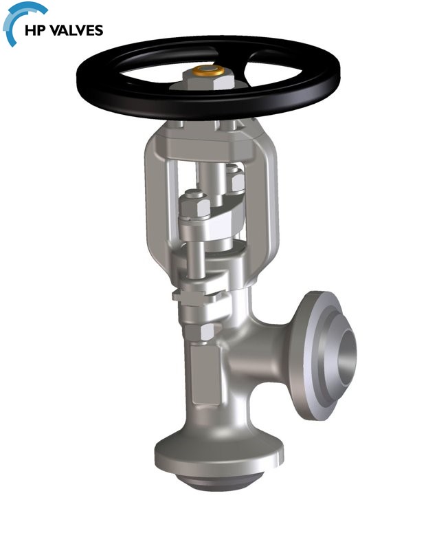
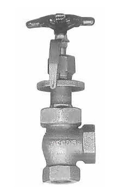
The boiler applications boil the water and therefore the impurities in water become sludge and get deposited at the bottom of the tanks and boilers. The blowdown systems are designed with more than one valve and are controlled by the user or operator. The GG25 Cast Iron Angle Blowdown Valveis one of the most used due to the high temperature applications. The sludge is removed by the opening of the valve at certain point. Some of the systems use automated time intervals while some other use the amount of sludge that builds up during the operations. The GS-C25 cast steel Steam Blowdown Valveis available from us with other types and grades as well. The purging of the sludge is made easy with the blow down valves. Depending on the water quality, the use of different types of valves such as the Cast Steel Blowdown Valvesis decided. You can contact us for more detailed information on the different types and prices of these valves.

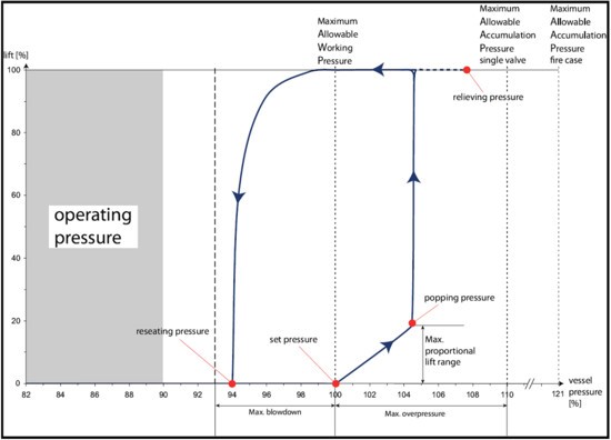
The pressure below the valve must increase above the set pressurebefore the safety valve reaches a noticeable lift. As a result of the restriction of flow between the disc and the adjusting ring, pressure builds up in the huddling chamber. The pressure now acts on an enlarged disc area. This increases the force Fp so that the additional spring force required to further compress the spring is overcome. The valve will open rapidly with a "pop", in most cases to its full lift.
Overpressure is the pressure increase above the set pressurenecessary for the safety valve to achieve full lift and capacity. The overpressure is usually expressed as a percentage of the set pressure. Codes and standards provide limits for the maximum overpressure. A typical value is 10%, ranging between 3% and 21% depending on the code and application.

In order to ensure that the maximum allowable accumulation pressure of any system or apparatus protected by a safety valve is never exceeded, careful consideration of the safety valve’s position in the system has to be made. As there is such a wide range of applications, there is no absolute rule as to where the valve should be positioned and therefore, every application needs to be treated separately.
A common steam application for a safety valve is to protect process equipment supplied from a pressure reducing station. Two possible arrangements are shown in Figure 9.3.3.
The safety valve can be fitted within the pressure reducing station itself, that is, before the downstream stop valve, as in Figure 9.3.3 (a), or further downstream, nearer the apparatus as in Figure 9.3.3 (b). Fitting the safety valve before the downstream stop valve has the following advantages:
• The safety valve can be tested in-line by shutting down the downstream stop valve without the chance of downstream apparatus being over pressurised, should the safety valve fail under test.
• When setting the PRV under no-load conditions, the operation of the safety valve can be observed, as this condition is most likely to cause ‘simmer’. If this should occur, the PRV pressure can be adjusted to below the safety valve reseat pressure.
Indeed, a separate safety valve may have to be fitted on the inlet to each downstream piece of apparatus, when the PRV supplies several such pieces of apparatus.
• If supplying one piece of apparatus, which has a MAWP pressure less than the PRV supply pressure, the apparatus must be fitted with a safety valve, preferably close-coupled to its steam inlet connection.
• If a PRV is supplying more than one apparatus and the MAWP of any item is less than the PRV supply pressure, either the PRV station must be fitted with a safety valve set at the lowest possible MAWP of the connected apparatus, or each item of affected apparatus must be fitted with a safety valve.
• The safety valve must be located so that the pressure cannot accumulate in the apparatus viaanother route, for example, from a separate steam line or a bypass line.
It could be argued that every installation deserves special consideration when it comes to safety, but the following applications and situations are a little unusual and worth considering:
• Fire - Any pressure vessel should be protected from overpressure in the event of fire. Although a safety valve mounted for operational protection may also offer protection under fire conditions,such cases require special consideration, which is beyond the scope of this text.
• Exothermic applications - These must be fitted with a safety valve close-coupled to the apparatus steam inlet or the body direct. No alternative applies.
• Safety valves used as warning devices - Sometimes, safety valves are fitted to systems as warning devices. They are not required to relieve fault loads but to warn of pressures increasing above normal working pressures for operational reasons only. In these instances, safety valves are set at the warning pressure and only need to be of minimum size. If there is any danger of systems fitted with such a safety valve exceeding their maximum allowable working pressure, they must be protected by additional safety valves in the usual way.
In order to illustrate the importance of the positioning of a safety valve, consider an automatic pump trap (see Block 14) used to remove condensate from a heating vessel. The automatic pump trap (APT), incorporates a mechanical type pump, which uses the motive force of steam to pump the condensate through the return system. The position of the safety valve will depend on the MAWP of the APT and its required motive inlet pressure.
This arrangement is suitable if the pump-trap motive pressure is less than 1.6 bar g (safety valve set pressure of 2 bar g less 0.3 bar blowdown and a 0.1 bar shut-off margin). Since the MAWP of both the APT and the vessel are greater than the safety valve set pressure, a single safety valve would provide suitable protection for the system.
Here, two separate PRV stations are used each with its own safety valve. If the APT internals failed and steam at 4 bar g passed through the APT and into the vessel, safety valve ‘A’ would relieve this pressure and protect the vessel. Safety valve ‘B’ would not lift as the pressure in the APT is still acceptable and below its set pressure.
It should be noted that safety valve ‘A’ is positioned on the downstream side of the temperature control valve; this is done for both safety and operational reasons:
Operation - There is less chance of safety valve ‘A’ simmering during operation in this position,as the pressure is typically lower after the control valve than before it.
Also, note that if the MAWP of the pump-trap were greater than the pressure upstream of PRV ‘A’, it would be permissible to omit safety valve ‘B’ from the system, but safety valve ‘A’ must be sized to take into account the total fault flow through PRV ‘B’ as well as through PRV ‘A’.
A pharmaceutical factory has twelve jacketed pans on the same production floor, all rated with the same MAWP. Where would the safety valve be positioned?
One solution would be to install a safety valve on the inlet to each pan (Figure 9.3.6). In this instance, each safety valve would have to be sized to pass the entire load, in case the PRV failed open whilst the other eleven pans were shut down.
If additional apparatus with a lower MAWP than the pans (for example, a shell and tube heat exchanger) were to be included in the system, it would be necessary to fit an additional safety valve. This safety valve would be set to an appropriate lower set pressure and sized to pass the fault flow through the temperature control valve (see Figure 9.3.8).
As soon as mankind was able to boil water to create steam, the necessity of the safety device became evident. As long as 2000 years ago, the Chinese were using cauldrons with hinged lids to allow (relatively) safer production of steam. At the beginning of the 14th century, chemists used conical plugs and later, compressed springs to act as safety devices on pressurised vessels.
Early in the 19th century, boiler explosions on ships and locomotives frequently resulted from faulty safety devices, which led to the development of the first safety relief valves.
In 1848, Charles Retchie invented the accumulation chamber, which increases the compression surface within the safety valve allowing it to open rapidly within a narrow overpressure margin.
Today, most steam users are compelled by local health and safety regulations to ensure that their plant and processes incorporate safety devices and precautions, which ensure that dangerous conditions are prevented.
The principle type of device used to prevent overpressure in plant is the safety or safety relief valve. The safety valve operates by releasing a volume of fluid from within the plant when a predetermined maximum pressure is reached, thereby reducing the excess pressure in a safe manner. As the safety valve may be the only remaining device to prevent catastrophic failure under overpressure conditions, it is important that any such device is capable of operating at all times and under all possible conditions.
Safety valves should be installed wherever the maximum allowable working pressure (MAWP) of a system or pressure-containing vessel is likely to be exceeded. In steam systems, safety valves are typically used for boiler overpressure protection and other applications such as downstream of pressure reducing controls. Although their primary role is for safety, safety valves are also used in process operations to prevent product damage due to excess pressure. Pressure excess can be generated in a number of different situations, including:
The terms ‘safety valve’ and ‘safety relief valve’ are generic terms to describe many varieties of pressure relief devices that are designed to prevent excessive internal fluid pressure build-up. A wide range of different valves is available for many different applications and performance criteria.
In most national standards, specific definitions are given for the terms associated with safety and safety relief valves. There are several notable differences between the terminology used in the USA and Europe. One of the most important differences is that a valve referred to as a ‘safety valve’ in Europe is referred to as a ‘safety relief valve’ or ‘pressure relief valve’ in the USA. In addition, the term ‘safety valve’ in the USA generally refers specifically to the full-lift type of safety valve used in Europe.
Pressure relief valve- A spring-loaded pressure relief valve which is designed to open to relieve excess pressure and to reclose and prevent the further flow of fluid after normal conditions have been restored. It is characterised by a rapid-opening ‘pop’ action or by opening in a manner generally proportional to the increase in pressure over the opening pressure. It may be used for either compressible or incompressible fluids, depending on design, adjustment, or application.
Safety valves are primarily used with compressible gases and in particular for steam and air services. However, they can also be used for process type applications where they may be needed to protect the plant or to prevent spoilage of the product being processed.
Relief valve - A pressure relief device actuated by inlet static pressure having a gradual lift generally proportional to the increase in pressure over opening pressure.
Relief valves are commonly used in liquid systems, especially for lower capacities and thermal expansion duty. They can also be used on pumped systems as pressure overspill devices.
Safety relief valve - A pressure relief valve characterised by rapid opening or pop action, or by opening in proportion to the increase in pressure over the opening pressure, depending on the application, and which may be used either for liquid or compressible fluid.
In general, the safety relief valve will perform as a safety valve when used in a compressible gas system, but it will open in proportion to the overpressure when used in liquid systems, as would a relief valve.
Safety valve- A valve which automatically, without the assistance of any energy other than that of the fluid concerned, discharges a quantity of the fluid so as to prevent a predetermined safe pressure being exceeded, and which is designed to re-close and prevent further flow of fluid after normal pressure conditions of service have been restored.
“4Matic” Blowdown valves are used to drain some amount of liquid from an equipment. It is attached to those equipment whose working fluids contain solid impurities. The nature of such impurities are that they don’t dissolve in the working fluid and it may get deposited on the surfaces of the equipment this causing problems in the operation of the equipment.

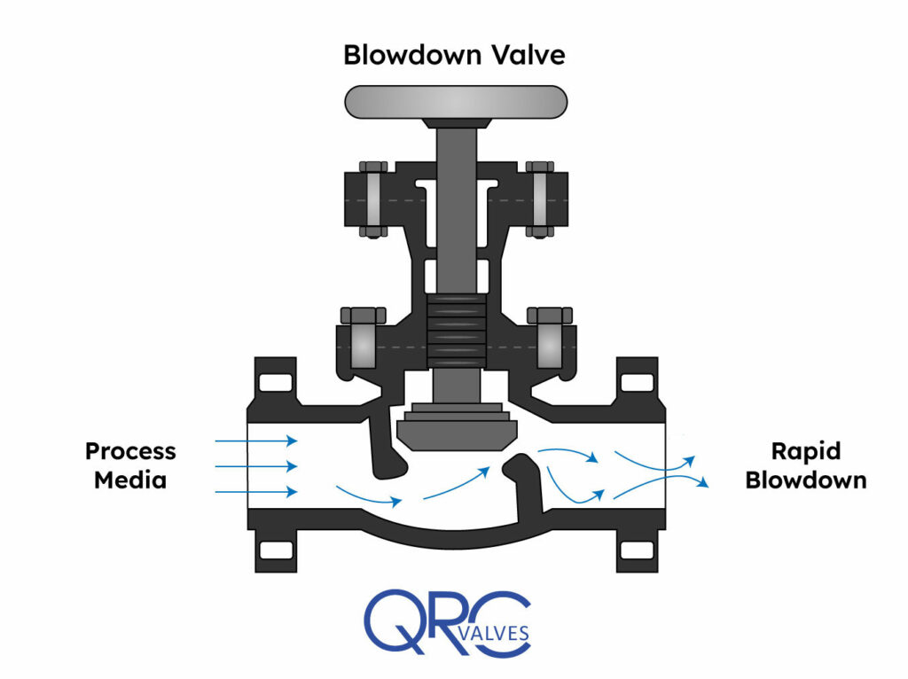
A blowdown valve’s main function is to control a continuous or intermittent flow of steam or fluid under high differential pressure. When installed in a system, they drain solid contaminants from the fluid. In this article, you will learn the working principle of a blowdown valve, review a blowdown valve diagram, and its use in boiler and compressor applications.
In industry, blowdown valves often attach to equipment where water is the working fluid. Usually, this water contains suspended solid impurities. As mechanisms such as vaporization or drafting occur in the system, the concentration of undissolved solids increases and hampers system performance. How? Some of these deposits may accumulate and form blockages that disrupt the flow. Also, the solids could deposit on the surface of the equipment and impact heat transfer. This reduces the efficiency of heat exchangers and designed cooling measures. Thus, blowdown valves along drain lines allow for the removal of these contaminants.
It is a common practice to use two blowdown valves in series. One acts as the seal valve, while the other is the main blowdown valve. Customarily, the seal valve opens first when draining, and closes last. However, to minimize erosion of the valve disk faces and seats, both may open simultaneously and rapidly.
In addition, care should be taken to avoid trapping scale and rust particles within the valve by briefly reopening it, after it has been shut. Especially if there was resistance when closing it initially. One important parameter in the operation of blowdown valves is the blowdown percentage. It refers to the ratio of the quantity of blowdown water (Vblowdown) to that of the feedwater (Vfeed) as the formula below shows.
For most applications, the blowdown percentage lies between 4% to 10%. However, it could be as low as 1% when the system has access to high-quality feedwater. On the other hand, it could reach above 20% in a critical system with poor quality feedwater. In any case, caution should be exercised to evacuate as many contaminants as possible, but without emptying the equipment.
The classification of blowdown valves depends on either the valve location or working interval. Generally, blowdown valves are installed at the surface or the bottom of the equipment, depending on the speed of solid impurities precipitation. Also, the valve may operate continuously or intermittently. Usually, surface blowdown valves operate in steady state, while bottom blowdown valves work intermittently.
This is suitable for applications where the rate of solid impurities precipitation is relatively slower. For a simple design of this type of valve, a pipe inserts near the surface of the water level. Then, water, along with impurities, goes through the pipe continuously as the valve is normally in the open position.
On the other hand, a more sophisticated design uses a swivel joint with a short length of pipe suspended on a float. Thus, it removes oil floating on the water surface. Typically, surface blowdown valves find use in equipment where a significant amount of vaporization exists. This is because as vaporization occurs, the contaminants, precipitate and remain on the water surface. Also, the outlet of these valves often feeds into a flash tank and provides heating for heat exchangers.
As the name implies, this type of blowdown valves installs at the bottom of the equipment. They are opened periodically to enable the evacuation of accumulated solid impurities and sludge. Unlike the surface blowdown valve, this type does not operate in a steady state. This is because prolonged opening decreases the water level quickly, thereby risking a shutdown of the equipment. A basic requirement of this valve is to provide tight shut-off even after repetitive blowdown operations. Also, the drainpipe diameter should be large enough so that the slug does not clog and block the flow.
The diagram above is that of a manually operated blowdown valve. Of importance, the orifice maintains fluid velocity below levels that could damage the trim. Also, the stem mates to the orifice for proper control, while the open yoke enables the operator to see the position of the plunger in the valve body. A long stroke length of the stem enables the prevention of water hammer, which occurs if the valve is opened or closed too quickly. At the exit, the angle of the orifice is intentionally made divergent, to minimize downstream piping erosion and noise.
Blowdown valves are common in boiler and compressor systems. In compressors, they serve to depressurize the gas in the system at critical times such as shutdown, restart, or in the case of an emergency. In boilers, they see more frequent use, where there could be both bottom blowdown valves, and a surface valve, in some cases.
Generally, in boilers, blowdown valves remove both suspended solids and sludge from the surface and bottom respectively. As a result, it prevents the foaming at the water surface which leads to unstable water levels and excessive passing on of liquid in the steam. When blowdown water leaves a boiler, it does so at high temperatures, creating a safety concern. For example, a boiler working at 100 psig typically discharges around 338 ℉. Thus, engineers must ensure controlled discharge occurs into a flash tank prior to disposal into drainage. Or, engineers may repurpose the heat elsewhere within the facility, perhaps to increase feedwater temperature.
In some cases, having just the flash tank is not enough. Especially if the blowdown will end up in a sewer system. Environmental regulations require that water comes into sewers at 140 ℉ or less. As a result, such facilities use a blowdown separator to separate steam from the liquid, and further cool down the temperature, as seen in the apparatus below.
A little product education can make you look super smart to customers, which usually means more orders for everything you sell. Here’s a few things to keep in mind about safety valves, so your customers will think you’re a genius.
A safety valve is required on anything that has pressure on it. It can be a boiler (high- or low-pressure), a compressor, heat exchanger, economizer, any pressure vessel, deaerator tank, sterilizer, after a reducing valve, etc.
There are four main types of safety valves: conventional, bellows, pilot-operated, and temperature and pressure. For this column, we will deal with conventional valves.
A safety valve is a simple but delicate device. It’s just two pieces of metal squeezed together by a spring. It is passive because it just sits there waiting for system pressure to rise. If everything else in the system works correctly, then the safety valve will never go off.
A safety valve is NOT 100% tight up to the set pressure. This is VERY important. A safety valve functions a little like a tea kettle. As the temperature rises in the kettle, it starts to hiss and spit when the water is almost at a boil. A safety valve functions the same way but with pressure not temperature. The set pressure must be at least 10% above the operating pressure or 5 psig, whichever is greater. So, if a system is operating at 25 psig, then the minimum set pressure of the safety valve would be 30 psig.
Most valve manufacturers prefer a 10 psig differential just so the customer has fewer problems. If a valve is positioned after a reducing valve, find out the max pressure that the equipment downstream can handle. If it can handle 40 psig, then set the valve at 40. If the customer is operating at 100 psig, then 110 would be the minimum. If the max pressure in this case is 150, then set it at 150. The equipment is still protected and they won’t have as many problems with the safety valve.
Here’s another reason the safety valve is set higher than the operating pressure: When it relieves, it needs room to shut off. This is called BLOWDOWN. In a steam and air valve there is at least one if not two adjusting rings to help control blowdown. They are adjusted to shut the valve off when the pressure subsides to 6% below the set pressure. There are variations to 6% but for our purposes it is good enough. So, if you operate a boiler at 100 psig and you set the safety valve at 105, it will probably leak. But if it didn’t, the blowdown would be set at 99, and the valve would never shut off because the operating pressure would be greater than the blowdown.
All safety valves that are on steam or air are required by code to have a test lever. It can be a plain open lever or a completely enclosed packed lever.
Safety valves are sized by flow rate not by pipe size. If a customer wants a 12″ safety valve, ask them the flow rate and the pressure setting. It will probably turn out that they need an 8×10 instead of a 12×16. Safety valves are not like gate valves. If you have a 12″ line, you put in a 12″ gate valve. If safety valves are sized too large, they will not function correctly. They will chatter and beat themselves to death.
Safety valves need to be selected for the worst possible scenario. If you are sizing a pressure reducing station that has 150 psig steam being reduced to 10 psig, you need a safety valve that is rated for 150 psig even though it is set at 15. You can’t put a 15 psig low-pressure boiler valve after the reducing valve because the body of the valve must to be able to handle the 150 psig of steam in case the reducing valve fails.
The seating surface in a safety valve is surprisingly small. In a 3×4 valve, the seating surface is 1/8″ wide and 5″ around. All it takes is one pop with a piece of debris going through and it can leak. Here’s an example: Folgers had a plant in downtown Kansas City that had a 6×8 DISCONTINUED Consolidated 1411Q set at 15 psig. The valve was probably 70 years old. We repaired it, but it leaked when plant maintenance put it back on. It was after a reducing valve, and I asked him if he played with the reducing valve and brought the pressure up to pop the safety valve. He said no, but I didn’t believe him. I told him the valve didn’t leak when it left our shop and to send it back.
If there is a problem with a safety valve, 99% of the time it is not the safety valve or the company that set it. There may be other reasons that the pressure is rising in the system before the safety valve. Some ethanol plants have a problem on starting up their boilers. The valves are set at 150 and they operate at 120 but at startup the pressure gets away from them and there is a spike, which creates enough pressure to cause a leak until things get under control.
If your customer is complaining that the valve is leaking, ask questions before a replacement is sent out. What is the operating pressure below the safety valve? If it is too close to the set pressure then they have to lower their operating pressure or raise the set pressure on the safety valve.
Is the valve installed in a vertical position? If it is on a 45-degree angle, horizontal, or upside down then it needs to be corrected. I have heard of two valves that were upside down in my 47 years. One was on a steam tractor and the other one was on a high-pressure compressor station in the New Mexico desert. He bought a 1/4″ valve set at 5,000 psig. On the outlet side, he left the end cap in the outlet and put a pin hole in it so he could hear if it was leaking or not. He hit the switch and when it got up to 3,500 psig the end cap came flying out like a missile past his nose. I told him to turn that sucker in the right direction and he shouldn’t have any problems. I never heard from him so I guess it worked.
If the set pressure is correct, and the valve is vertical, ask if the outlet piping is supported by something other than the safety valve. If they don’t have pipe hangers or a wall or something to keep the stress off the safety valve, it will leak.
There was a plant in Springfield, Mo. that couldn’t start up because a 2″ valve was leaking on a tank. It was set at 750 psig, and the factory replaced it 5 times. We are not going to replace any valves until certain questions are answered. I was called to solve the problem. The operating pressure was 450 so that wasn’t the problem. It was in a vertical position so we moved on to the piping. You could tell the guy was on his cell phone when I asked if there was any piping on the outlet. He said while looking at the installation that he had a 2″ line coming out into a 2×3 connection going up a story into a 3×4 connection and going up another story. I asked him if there was any support for this mess, and he hung up the phone. He didn’t say thank you, goodbye, or send me a Christmas present.
A spring-loaded relief valve can be thought of as a spring /mass system which is why relief valves chatter. Researchers have found significant differences in the stability of relief valves based on the design of their internals. One recent study found that with 6 feet of inlet piping, valves from Manufacturer X were stable in 50% of the tests while valves from Manufacturer Z where stable in 100% of these tests.¹ Smith & Burgess Laboratory research has confirmed these findings. However, relief systems designers tend to downplay (if not ignore) the importance of the mechanical design of relief valves which is important to stability. Therefore, this article discusses the fundamentals of the design parameters for the internals of a relief valve. The intent is to provide design considerations and general operation information for use by relief systems designers, specifically assisting with the understanding of the effects of valve design on stability.
Modern relief valves are wonderfully modular.The internal parts for a relief valve (valve disc,disc holder, blowdown ringandspring) can be interchanged for ones with a different design to customize valve performance based on the application, fluid service, and set pressure.Valve disccan be metal-to-metal or soft seats. Soft seat designs use an elastomer to create a better seal between thevalvediscand thenozzle. Relief valves with elastomer seats have limitations and can only be used in certain applications.Disc holdersare generally designed to allow thevalve discto float which provides an angular movement that reduces seat leakage from minor misalignments (ensuring that thevalve dischas 360 degrees of contact with thenozzle). Thedisc holderoutside diameter, shape and thickness plays an important role in determining the valve performance by defining the shape of thehuddling chamber. Thehuddling chambercan also be defined by theblowdown ring(s). Thering(s)can also be swapped to different sized and shapedringsto adjust performance based on the expected relief fluid.Springsare selected to keep the valve closed and must fit inside thevalve bonnet. The force thespringexerts is an important design criteria for a relief device and varies depending on the relief fluid, valve size and set pressure.
Spring loaded relief valves are known as "pop action" relief valves as they typically pop open at their set pressure. Initially, the pressure differential across thevalve discthat creates the force to over come the spring force and open the valve.The pop action occurs because mosthuddling chambersare designed with an area that is approximately 10%-30% larger than thevalve seat(as thedisc holderis bigger than thevalve disc). Once the pressure under the seat is enough to lift thevalve discoff thenozzle, there is a step change in the upward forces on thespringand the valve "pops" open. The shape of thehuddling chamber(created by the shape and size of thedisc holder), the position and shape of theblowdown ring, and the characteristics of the fluid being relieved together determine the initial opening force and the initial lift of the valve.
Blowdown ringsare adjustable rings with a design shape that modifies the effluent flow path andhuddling chamberbased on the position. For process valves, a singleblowdown ringis typically threaded onto thenozzleand can be adjusted vertically up or down. Manufacturers will specify a recommended position relative to contact with thevalve disc. The position of theblowdown ringis fixed with a locking screw. The position of theblowdown ringchanges the blowdown (or reseat) pressure. For valves with a singleblowdown ring, the closer theblowdown ringis to thenozzle, the lower the pressure in the system will need to be for the valve to close (more blowdown). Other relief valves have multipleblowdown rings. Each manufacturer designs a uniqueblowdown ringto compliment other aspects of the relief valve design. Smith & Burgess" testing confirms that position and design ofblowdown ring(s)affects valve stability.
Relief Valve manufactures generally select aspringthat is designed for the set pressure of the valve. Thespringthat is selected will have a pressure range that thespringcan be applied. In many cases, there may be more than onespringthat can be used with each relief valve each having a different spring constant. The stifferspringmay have a range that is higher than the softerspringbut still meet the overall requirements for set pressure. The selection of thespringwill affect stability as the specific spring influences the natural frequency of the valve and can also affect the blowdown.
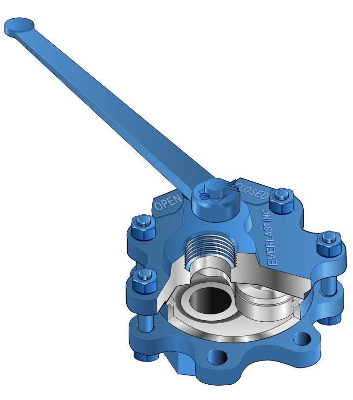
Control Specialties representsEverlasting Blowdown Valves, Penn Blow Down Separators andSpirax Sarco Blowdown Control Systems. Everlasting manufacturers the most recognized blow down valves used for boiler blow down, surface blow down, water column drain and shut off valve blow down. Penn Separator is noted for their intermittent blow down equipment and Spirax Sarco manufactures a control system that minimizes the amount of boiler blow down required.


 8613371530291