
blowdown safety valve in stock
Blowdown Valves keep boilers clean. Blowdown valves are used to vent the impurities, sediment, and other solids that are present in boiler water. They are opened periodically to prevent buildup. They are also used to regulate the conductivity of the water in a boiler, because higher electrical conductivity causes scale to build up faster.
Blowdown valves come in two varieties, fast-open and slow-open. Fast-open valves act as the quick cutoff, while slow-open valves allow modulation of the water flow.
During a blowdown, the fast-open valve is opened first. This feeds the slow-open valve, which can then be opened gradually for operator safety and to prevent thermal shock to the drain pipes.
There are four locations where blowdown valves are typically installed:The bottom of the sight glassto keep water readings accurateThe bottom of the boilerto remove heavier solids, sediment, and impuritiesLevel with the surface of the water inside the boilerto allow floating impurities to be blown outThe low water cutoff, to confirm that it is operating properly
Without the blowdown valve in place, sediment and other impurities would gradually build up along the inside surface of the boiler. This would not only reduce the boiler’s operating efficiency, it could also become a safety hazard by creating uneven heating and metal stress.
Blowdown valves also regulate electrical conductivity in the boiler water by regulating the amount of suspended solids. Higher electrical conductivity creates faster scale buildup, which reduces a boiler’s operating efficiency. Higher conductivity also decreases the life of the boiler by accelerating the corrosive effects of the oxygen inside.
Things to Consider about Blowdown Valves:When the blowdown valve is opened, the water is extremely hot, and has a lot of steam pressure behind it. Always use extreme caution and be aware of your environment when operating a blowdown valve.Always wear proper protective equipment when operating a blowdown valve.Open the valve slowly. This is not only for operator safety, it also reduces thermal shock to the venting pipes.After completing a blowdown, momentarily crack the slow-open valve to release the pressure between the valves.
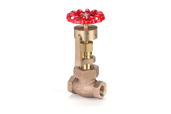
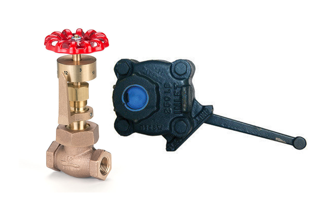
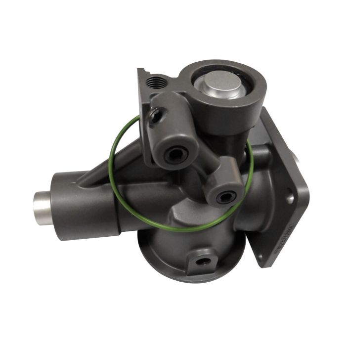
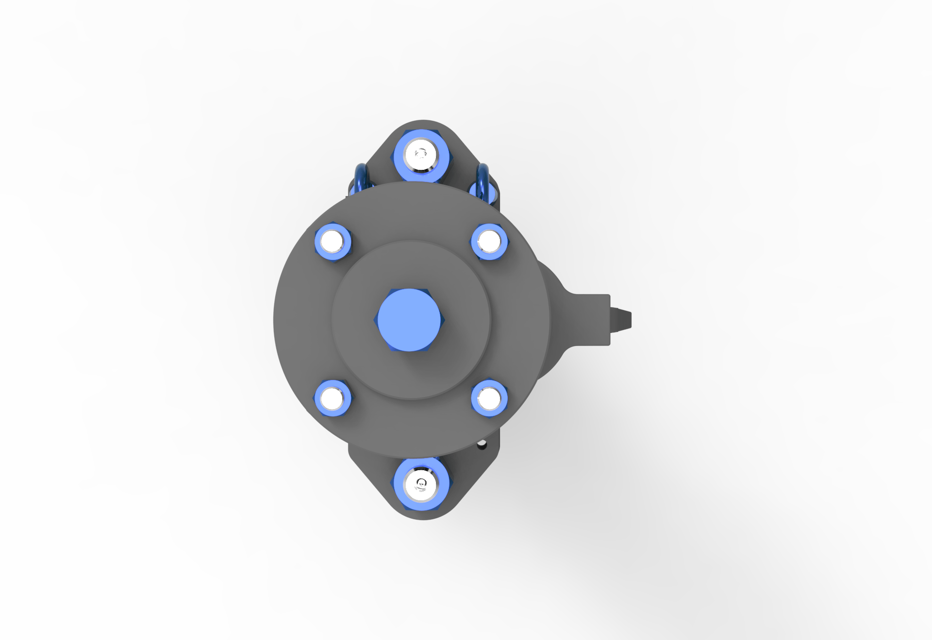
Everlasting lever operated quick-opening, lever and gear operated, angle pattern blow-off valve with a 1-1/2" flanged connection with a maximum steam service of 250 psi. Learn More

The Consolidated 19000 Series valve provides quality performance in seat tightness, capacity, and blowdown on most media. It surpasses ASME code requirements and is CE compliant to European PED specifications in functional performance and overpressure protection.
The Type 19000 safety relief valve is suitable for overpressure protection in chemical, petrochemical, refinery, power generation (nuclear and commercial), and other commercial applications.

In order to ensure that the maximum allowable accumulation pressure of any system or apparatus protected by a safety valve is never exceeded, careful consideration of the safety valve’s position in the system has to be made. As there is such a wide range of applications, there is no absolute rule as to where the valve should be positioned and therefore, every application needs to be treated separately.
A common steam application for a safety valve is to protect process equipment supplied from a pressure reducing station. Two possible arrangements are shown in Figure 9.3.3.
The safety valve can be fitted within the pressure reducing station itself, that is, before the downstream stop valve, as in Figure 9.3.3 (a), or further downstream, nearer the apparatus as in Figure 9.3.3 (b). Fitting the safety valve before the downstream stop valve has the following advantages:
• The safety valve can be tested in-line by shutting down the downstream stop valve without the chance of downstream apparatus being over pressurised, should the safety valve fail under test.
• When setting the PRV under no-load conditions, the operation of the safety valve can be observed, as this condition is most likely to cause ‘simmer’. If this should occur, the PRV pressure can be adjusted to below the safety valve reseat pressure.
Indeed, a separate safety valve may have to be fitted on the inlet to each downstream piece of apparatus, when the PRV supplies several such pieces of apparatus.
• If supplying one piece of apparatus, which has a MAWP pressure less than the PRV supply pressure, the apparatus must be fitted with a safety valve, preferably close-coupled to its steam inlet connection.
• If a PRV is supplying more than one apparatus and the MAWP of any item is less than the PRV supply pressure, either the PRV station must be fitted with a safety valve set at the lowest possible MAWP of the connected apparatus, or each item of affected apparatus must be fitted with a safety valve.
• The safety valve must be located so that the pressure cannot accumulate in the apparatus viaanother route, for example, from a separate steam line or a bypass line.
It could be argued that every installation deserves special consideration when it comes to safety, but the following applications and situations are a little unusual and worth considering:
• Fire - Any pressure vessel should be protected from overpressure in the event of fire. Although a safety valve mounted for operational protection may also offer protection under fire conditions,such cases require special consideration, which is beyond the scope of this text.
• Exothermic applications - These must be fitted with a safety valve close-coupled to the apparatus steam inlet or the body direct. No alternative applies.
• Safety valves used as warning devices - Sometimes, safety valves are fitted to systems as warning devices. They are not required to relieve fault loads but to warn of pressures increasing above normal working pressures for operational reasons only. In these instances, safety valves are set at the warning pressure and only need to be of minimum size. If there is any danger of systems fitted with such a safety valve exceeding their maximum allowable working pressure, they must be protected by additional safety valves in the usual way.
In order to illustrate the importance of the positioning of a safety valve, consider an automatic pump trap (see Block 14) used to remove condensate from a heating vessel. The automatic pump trap (APT), incorporates a mechanical type pump, which uses the motive force of steam to pump the condensate through the return system. The position of the safety valve will depend on the MAWP of the APT and its required motive inlet pressure.
This arrangement is suitable if the pump-trap motive pressure is less than 1.6 bar g (safety valve set pressure of 2 bar g less 0.3 bar blowdown and a 0.1 bar shut-off margin). Since the MAWP of both the APT and the vessel are greater than the safety valve set pressure, a single safety valve would provide suitable protection for the system.
Here, two separate PRV stations are used each with its own safety valve. If the APT internals failed and steam at 4 bar g passed through the APT and into the vessel, safety valve ‘A’ would relieve this pressure and protect the vessel. Safety valve ‘B’ would not lift as the pressure in the APT is still acceptable and below its set pressure.
It should be noted that safety valve ‘A’ is positioned on the downstream side of the temperature control valve; this is done for both safety and operational reasons:
Operation - There is less chance of safety valve ‘A’ simmering during operation in this position,as the pressure is typically lower after the control valve than before it.
Also, note that if the MAWP of the pump-trap were greater than the pressure upstream of PRV ‘A’, it would be permissible to omit safety valve ‘B’ from the system, but safety valve ‘A’ must be sized to take into account the total fault flow through PRV ‘B’ as well as through PRV ‘A’.
A pharmaceutical factory has twelve jacketed pans on the same production floor, all rated with the same MAWP. Where would the safety valve be positioned?
One solution would be to install a safety valve on the inlet to each pan (Figure 9.3.6). In this instance, each safety valve would have to be sized to pass the entire load, in case the PRV failed open whilst the other eleven pans were shut down.
If additional apparatus with a lower MAWP than the pans (for example, a shell and tube heat exchanger) were to be included in the system, it would be necessary to fit an additional safety valve. This safety valve would be set to an appropriate lower set pressure and sized to pass the fault flow through the temperature control valve (see Figure 9.3.8).
As soon as mankind was able to boil water to create steam, the necessity of the safety device became evident. As long as 2000 years ago, the Chinese were using cauldrons with hinged lids to allow (relatively) safer production of steam. At the beginning of the 14th century, chemists used conical plugs and later, compressed springs to act as safety devices on pressurised vessels.
Early in the 19th century, boiler explosions on ships and locomotives frequently resulted from faulty safety devices, which led to the development of the first safety relief valves.
In 1848, Charles Retchie invented the accumulation chamber, which increases the compression surface within the safety valve allowing it to open rapidly within a narrow overpressure margin.
Today, most steam users are compelled by local health and safety regulations to ensure that their plant and processes incorporate safety devices and precautions, which ensure that dangerous conditions are prevented.
The principle type of device used to prevent overpressure in plant is the safety or safety relief valve. The safety valve operates by releasing a volume of fluid from within the plant when a predetermined maximum pressure is reached, thereby reducing the excess pressure in a safe manner. As the safety valve may be the only remaining device to prevent catastrophic failure under overpressure conditions, it is important that any such device is capable of operating at all times and under all possible conditions.
Safety valves should be installed wherever the maximum allowable working pressure (MAWP) of a system or pressure-containing vessel is likely to be exceeded. In steam systems, safety valves are typically used for boiler overpressure protection and other applications such as downstream of pressure reducing controls. Although their primary role is for safety, safety valves are also used in process operations to prevent product damage due to excess pressure. Pressure excess can be generated in a number of different situations, including:
The terms ‘safety valve’ and ‘safety relief valve’ are generic terms to describe many varieties of pressure relief devices that are designed to prevent excessive internal fluid pressure build-up. A wide range of different valves is available for many different applications and performance criteria.
In most national standards, specific definitions are given for the terms associated with safety and safety relief valves. There are several notable differences between the terminology used in the USA and Europe. One of the most important differences is that a valve referred to as a ‘safety valve’ in Europe is referred to as a ‘safety relief valve’ or ‘pressure relief valve’ in the USA. In addition, the term ‘safety valve’ in the USA generally refers specifically to the full-lift type of safety valve used in Europe.
Pressure relief valve- A spring-loaded pressure relief valve which is designed to open to relieve excess pressure and to reclose and prevent the further flow of fluid after normal conditions have been restored. It is characterised by a rapid-opening ‘pop’ action or by opening in a manner generally proportional to the increase in pressure over the opening pressure. It may be used for either compressible or incompressible fluids, depending on design, adjustment, or application.
Safety valves are primarily used with compressible gases and in particular for steam and air services. However, they can also be used for process type applications where they may be needed to protect the plant or to prevent spoilage of the product being processed.
Relief valve - A pressure relief device actuated by inlet static pressure having a gradual lift generally proportional to the increase in pressure over opening pressure.
Relief valves are commonly used in liquid systems, especially for lower capacities and thermal expansion duty. They can also be used on pumped systems as pressure overspill devices.
Safety relief valve - A pressure relief valve characterised by rapid opening or pop action, or by opening in proportion to the increase in pressure over the opening pressure, depending on the application, and which may be used either for liquid or compressible fluid.
In general, the safety relief valve will perform as a safety valve when used in a compressible gas system, but it will open in proportion to the overpressure when used in liquid systems, as would a relief valve.
Safety valve- A valve which automatically, without the assistance of any energy other than that of the fluid concerned, discharges a quantity of the fluid so as to prevent a predetermined safe pressure being exceeded, and which is designed to re-close and prevent further flow of fluid after normal pressure conditions of service have been restored.
(a) Safety relief valves shall be so constructed that no shocks detrimental to the valve or pressure vessel are produced when lifting or closing. Safety relief valves shall be designed to open sharply and reach full lift and capacity at the maximum accumulation. Valve closure after popping shall be clean and sharp. Safety relief valves shall operate satisfactorily without wiredrawing and chattering at any stage of operation.
(b) Safety relief valves having adjustable blow-down construction shall be adjusted to close after blowing down not more than 5 percent of the set pressure. Valves shall be adjusted to pop within a tolerance of plus or minus 3 percent of the set pressure, except that for pressures of 70 p.s.i. and below, the tolerance in popping pressure shall not vary more than plus or minus 2 p.s.i.

Safety Relief ValvePioneers in the industry, we offer safety relief valve, pressure safety valve, thermal relief valve, sanitary safety valve, flange end safety relief valve and high pressure relief valve from India.

A fire-tube boiler can be fitted with one or more safety valves on the top of its shell, with each set to open when the boiler reaches its design pressure. Noisolation valvesor restrictions should be integrated between the safety valve(s) and boiler. If the valves are not installed directly onto the boiler shell, the pipework connecting the valves to the boiler must be kept clear of blockagesand water, and this must be confirmed by periodic testing.
Once a safety valve opens, steam is discharged via the exhaust pipe. Exhaust pipes must be designed to encounter as few bends as possible, be as short as possible, to have no reduction in pipe section (no internal pipe diameter reduction), and should lead to asafe point of discharge(typically outside the boiler house).
Water must be drained from the safety valve or exhaust pipework via a drainpipe. Drainpipes may be connected to holes drilled into the lowest section of the exhaust pipework, or, directly to drain holes in the safety valve body; these drains are not to be confused with the blowdown ring locking bolt, if one is fitted.
Where two safety valves are fitted, it is common that one is set just belowthe boiler’s design pressure. It is vital that each safety valve permits the full flow of steam produced when the boiler is operating at maximum capacity i.e. when the boiler is producing the maximum amount of steam it can possibly produce. If safety valves are sized correctly, a boiler can be firing at full capacity without the steam pressure exceeding design limits (because the safety valve(s) relieves pressure at a faster rate than it is accumulated).
There are various types of safety valve, including high lift and improved high lift valves, which use the force of escaping steam to open a winged valve plug to achieve greater steam flow rates. In addition to this, some valves integrate a pistonat the bottom of the spring chamber. The piston has a larger surface area than the valve plug, which leads to the valve opening with a definitive ‘pop’ sound.
Some boiler safety valves include a blowdown ring. The blowdown ring can raise or lower the valve seat ring and is used to control the amount of blowdown through the valve. This ring is locked by a bolt that protrudes through the valve and into the adjusting ring segments.
Boiler safety valves should be fitted with an easing gear (looks like a handle), used, when necessary, to rapidly release boiler pressure. Easing gears can also be used for testing a safety valve, ensuring the spindle has freedom of movement and that the valve operating mechanism functions as intended. Easing gear testing is often not conducted due to operators having difficulty with the valves resealing, but this is generally only the case with valves that are not tested often enough. Actuating the easing gear several times is often all it takes to dislodge debris from the sealing area and allow the valve to seal again. For safe operation, the easing gear handle is usually connected via steel cables to an area neighbouring the boiler.
Like pressure gauges, all safety valves should be stripped, inspected, and calibrated, at least once a year; maintenance usually occurs during statutory inspections. Calibration of each valve should be conducted by a competent person, and any valve adjustment (including the blowdown ring) should be approved and sealed by the authorised inspector. After testing and calibration, all valves should be correctly marked, suitable certificates issued, and accurate records maintained.
An accumulation test can be conducted to ensure a safety valve can relieve over-pressure steam when the boiler burner is operating at maximum capacity. Accumulation testing of safety valves must be repeated after any alterations are made to the boiler e.g. replacement of a safety valve, fuel change, or changes to the control system. If, during an accumulation test, boiler pressure rises by more than 10% of its design pressure, the test must be aborted. Before the boiler is re-tested, amendments must be made to either the safety valve relieving capacity, thesafety valve exhaust pipework, or the boiler’s steaming capacity, to ensure the 10% limit is never exceeded.
Reliefand safetyvalves prevent equipment damage by relieving over-pressurisation of fluid systems. The main difference between a relief valve and a safety valve is the extent of opening at the set-point pressure.
A relief valve gradually opens as the inlet pressure increases above the set-point. A relief valve opens only as necessary to relieve the over-pressure condition. Relief valves are typically used for liquid systems.
A safety valve rapidly‘pops’ fully openas soon as the pressure setting is reached and will stay fully open until the pressure drops below the reset pressure. The reset pressure is lower than the actuating set-point pressure. The difference between the actuating pressure set-point, and the pressure at which the safety valve resets, is called blowdown. Safety valves are typically used for gas or vapour systems.
A safety relief valve may open fully, or proportionally, once the pressure setting is reached. SRVs may be used for any fluid system (gas, liquid, or vapour).
A spring-loaded relief valve can be thought of as a spring /mass system which is why relief valves chatter. Researchers have found significant differences in the stability of relief valves based on the design of their internals. One recent study found that with 6 feet of inlet piping, valves from Manufacturer X were stable in 50% of the tests while valves from Manufacturer Z where stable in 100% of these tests.¹ Smith & Burgess Laboratory research has confirmed these findings. However, relief systems designers tend to downplay (if not ignore) the importance of the mechanical design of relief valves which is important to stability. Therefore, this article discusses the fundamentals of the design parameters for the internals of a relief valve. The intent is to provide design considerations and general operation information for use by relief systems designers, specifically assisting with the understanding of the effects of valve design on stability.
Modern relief valves are wonderfully modular.The internal parts for a relief valve (valve disc,disc holder, blowdown ringandspring) can be interchanged for ones with a different design to customize valve performance based on the application, fluid service, and set pressure.Valve disccan be metal-to-metal or soft seats. Soft seat designs use an elastomer to create a better seal between thevalvediscand thenozzle. Relief valves with elastomer seats have limitations and can only be used in certain applications.Disc holdersare generally designed to allow thevalve discto float which provides an angular movement that reduces seat leakage from minor misalignments (ensuring that thevalve dischas 360 degrees of contact with thenozzle). Thedisc holderoutside diameter, shape and thickness plays an important role in determining the valve performance by defining the shape of thehuddling chamber. Thehuddling chambercan also be defined by theblowdown ring(s). Thering(s)can also be swapped to different sized and shapedringsto adjust performance based on the expected relief fluid.Springsare selected to keep the valve closed and must fit inside thevalve bonnet. The force thespringexerts is an important design criteria for a relief device and varies depending on the relief fluid, valve size and set pressure.
Spring loaded relief valves are known as "pop action" relief valves as they typically pop open at their set pressure. Initially, the pressure differential across thevalve discthat creates the force to over come the spring force and open the valve.The pop action occurs because mosthuddling chambersare designed with an area that is approximately 10%-30% larger than thevalve seat(as thedisc holderis bigger than thevalve disc). Once the pressure under the seat is enough to lift thevalve discoff thenozzle, there is a step change in the upward forces on thespringand the valve "pops" open. The shape of thehuddling chamber(created by the shape and size of thedisc holder), the position and shape of theblowdown ring, and the characteristics of the fluid being relieved together determine the initial opening force and the initial lift of the valve.
Blowdown ringsare adjustable rings with a design shape that modifies the effluent flow path andhuddling chamberbased on the position. For process valves, a singleblowdown ringis typically threaded onto thenozzleand can be adjusted vertically up or down. Manufacturers will specify a recommended position relative to contact with thevalve disc. The position of theblowdown ringis fixed with a locking screw. The position of theblowdown ringchanges the blowdown (or reseat) pressure. For valves with a singleblowdown ring, the closer theblowdown ringis to thenozzle, the lower the pressure in the system will need to be for the valve to close (more blowdown). Other relief valves have multipleblowdown rings. Each manufacturer designs a uniqueblowdown ringto compliment other aspects of the relief valve design. Smith & Burgess" testing confirms that position and design ofblowdown ring(s)affects valve stability.
Relief Valve manufactures generally select aspringthat is designed for the set pressure of the valve. Thespringthat is selected will have a pressure range that thespringcan be applied. In many cases, there may be more than onespringthat can be used with each relief valve each having a different spring constant. The stifferspringmay have a range that is higher than the softerspringbut still meet the overall requirements for set pressure. The selection of thespringwill affect stability as the specific spring influences the natural frequency of the valve and can also affect the blowdown.
Many people probably know that the National Board operates a capacity certification program and a valve repair program where we test many pressure relief devices. I want to talk about the background and requirements of that program and the applicability of our testing data to reliability for industry. As a result of years of testing, we have accumulated a good deal of data that helps us analyze the quality and reliability of the equipment. We want to use the data to determine what industry can expect when they receive a certified pressure relief device, pressure relief valve, or rupture disk device.
Two samples are selected every six years and tested at an ASME-certified lab. All test requirements come from the ASME Boiler and Pressure Vessel Code. Through the code, the National Board has been designated the responsibility to manage and run that certification program using the ASME boiler code rules. National Board inspectors travel to the manufacturers’ sites. We also deal with valve assemblers and rupture disk manufacturers. A big part of their responsibility when visiting the site is to look at the manufacturing, assembly, and test procedures, and make sure we get a good representative sample of what that manufacturer is capable of doing.
In some cases we will actually take valves right from shelf stock, particularly from manufacturers that mass produce their product and have large quantities of valves in stock. One selection technique is to go into the warehouse and say, “Give me one of those and one of those.” Sometimes they will dust off the box, but we are trying to get an accurate sample. Sometimes they are testing a valve they are building for the inspector while he"s there, but in that case they are looking at the assembly and test procedures and trying to see if it’s a good representative sample.
The program for individual design is not meant to be statistical in nature, so we are not testing a certain percentage of devices: just those two products every six years. It may be more than two if a test failure occurs. If there is a failure, the manufacturer has to test two additional samples. If they get past that test and still have a problem, a formal corrective action program is implemented. They have to analyze their failure, report on what happened (the cause), and explain what corrective actions they will take. And potentially, a manufacturer could actually lose the ability to put the code stamp on their product, so it"s an important test. The manufacturers have a lot riding on it because if the product passes, they can produce that valve for a six-year period of time. The tests are conducted at ASME/National Board-certified test labs, which include the National Board Testing Lab in Columbus, Ohio, but there are also about 10 other laboratories that are operated by valve manufacturers and rupture disk manufacturers.
Slide 5: We analyzed information starting with the year 2000. I chose that year because it gave me a lot of tests, but also the code rules for rupture disk certification went into effect in the "98 code, and by the year 2000, rupture disks were a well-certified device under ASME Code Section 8, and manufacturers had started to certify those devices. So it gave them a wider variety of equipment than we had seen before, because until then we were just testing pressure relief valves, and the non-reclosing devices were not well represented in the formal testing that we did, although they were being used out in the industry. It includes valve repair verification tests.
So although we talked about testing done on new product, as part of the valve repair certification process, the valve repair applicant has to repair several sample valves. Those are sent to a certified test lab and tested to exactly the same procedure that a new device is tested under. And while we always say a goal of the valve repair program is to return the valve to a like-new condition, as far as a user is concerned, if we get a repaired pressure relief valve, you should be able to expect that valve to do exactly what a new valve would do. It"s a certified device to begin with. It"s put through a program to inspect it, repair it as necessary, reset it, and get it back to that like-new condition. So I included all these valve repair verification tests. The typical test program for a repair outfit is doing a steam valve, an air valve, and a water valve, depending on the scope of work. And I threw those into the hopper; I treated those just like any other new valve that would be coming from the manufacturer.
We do tests for research and development projects and informational tests (what we call provisional testing). Provisional testing is the test a manufacturer does when they are first getting their design certified. Those tests are essentially prototypes. They are not valves that have truly gone into production, which doesn"t happen until a two-valve test is performed. So none of that was included, because they are still tweaking their design and getting it to the point at which they think it"s capable of being put through the final tests, and then to the production tests, which are the proof of the pudding.
It doesn"t include what we call investigation tests. I will talk a little bit about some of that test data. We don"t have a lot of it, but we do have enough to draw a couple conclusions, but it"s not indicative of the new product going out the door. Some of the limitations of this information based on the economics represents the lower pressures and smaller sizes of valves. So what we and other test labs can do is go up to three-, four-inch inlet sizes. Our pressures and capacities are necessarily limited because to put a pressure relief valve through a full-flow test, you need a lot of support equipment. We run boilers (we previously ran large air compressors but we"ve switched to a nitrogen system) but we have a lot of capital tied up in that. And as you double the pressure, the costs go up exponentially. So our tests are limited; we don"t do eight- and twelve-inch valves. The theory is that the valves are scaled up appropriately, but most of the testing we do is lower sizes and pressures. Hopefully that reflects more typical industrial equipment. We don"t get super-critical boilers, but there are large numbers of boilers with a 150-pound safety valve, and we have covered those pretty well.
Section III – 12 tests (These Section III valves were likely nuclear valves that got repaired as part of a repair demonstration. We don"t normally test many nuclear valves. They are the same physical equipment as you see in either Section 1 or Section 8.)
This is the bulk of the work we do; a wide variety of all different types of Section 8 pressure relief devices. In regards to test medium used: steam is about 25 percent and air is almost half. Air represents all the industrial gases. And then water tests are at about 25 percent. That represents valves for liquid service.
The test outcomes are based on the criteria we put in our database. After we run a test, we give it a designation as to the outcome of the test. Eighty-five percent of the valves passed. The biggest ones are set pressure failures and failures of capacity, with the next biggest elements, and I will talk a little bit about each category.
What I have is a plot of all the pressure relief valves, looking first at set pressure. Anything we called a failure is a failure to meet the ASME code set pressure tolerance. It"s cut and dried. If you fail it, you have to retest. But what we tried to do is see how wide those failures were, their distribution, and where test failures might potentially affect the pressurized equipment where that valve might be installed.
Slides 11-12: This distribution is the measured set pressure over the nameplate set pressure. The numbers below the 100% line are valves that opened underneath the nameplate set pressure requirement. The little tilted spot in the middle is all the valves that passed. And then as we go up on the right-hand side, those are the valves that failed but where the set pressure was actually high. And that to me is the real area of concern. A valve that opens low indicates an operational issue. But what we don"t want are valves that open high.
One glitch we discovered were a few valves that showed up at 400% above the set pressure. Normally we stop a test essentially at one and a half times the set pressure of the valve.
Occasionally we had some valves where set pressure was in bars, the test pressure was in psi, and if you tried to compare those numbers you didn’t necessarily get the right answer. Then what is the unsafe level? Where should we be concerned? A lot of times when people do this analysis, they will look at the hydrostatic test pressure. I do not believe that is conservative enough. That was good when a pressure vessel or boiler was manufactured.
We did an overload test on it and made sure it was good. But as that equipment goes into service over time, we know it"s degraded and there are other things happening to it. The criteria I used for what I call ‘the real bad actors’ was all of the devices that were over 116 % of the nameplate set pressure. That is the Section 8 overpressure limit for a system with multiple pressure relief devices. And if we get above that, we also reference it in the NBIC as a place for taking up the valve for an inservice test. We are going to stop at that point. I"m concerned with anything above that. So that was my first set of data where I"m thinking these are really not the way we would want them to be.
Then we get to valve capacity. The capacity includes valves that didn"t flow what they were rated to flow. A common cause is when valves are over pressured, they will hit a point where they get a secondary lift, and if someone doesn"t fine tune that valve properly, secondary lift isn"t quite achieved. It’s a test-and-tune issue; it"s not necessarily a design issue, but people really understanding how the equipment works. We do have a number of liquid valves that showed up, and again, if a valve doesn"t meet its rated capacity by the code-specified overpressure, it"s a test failure. But we have a number of liquid valves that would open just above whatever the specified overpressure is, typically 10 percent for a Section 8 valve.
So we did have a number of comments for those. And this also includes rupture disks where the flow resistance, which is the Kr valveor minimum net flow area, did not meet specifications.
Slides 13-14: This is my first graph of the distribution of our valve capacity. These are valves that were designated as failures, and we have the measured capacity divided by what the valve is actually rated for. So you can see, it starts at zero and works its way up. It should end at one but I had two or three tests where we called it a capacity failure, but it actually flowed more than the nameplate. Every so often we do run across valves that are misidentified, and sometimes that can be an issue. What I used as a measuring stick was stuff that was less than half of what it was rated at. That tells me it"s a valve that probably was not just a secondary lift issue. There was something really wrong with it. And that ended up being about a half percent of all the tests that were done.
We had about 1% of tests where we just didn"t have a measured capacity. Many were liquid valves. So we will take that test (the set pressure on those is where it first starts to have a trickling flow) and we will keep increasing the pressure until that valve pops open. And if that pressure occurred more than 10% above the set pressure, that valve was a capacity failure. We had a number of those that were about 12-15% above the set point. That information goes to the manufacturer and it can help them figure out their problem. Those valves were not counted in the case where we knew where they opened. We know that once they did open, they would probably work fine. But if you don"t hit it by that 10%, you have got to go through and do another test and improve your product to make it better. The rupture disk Kr number is used a little bit differently.
Slide 17: We had about two percent of what we reported as blow-down failures. These are not included in the final analysis because in reality we look at blow-down ultimately as more of an operational issue. It"s a concern to the user and to the boiler operator. It took two examples: one, we did have some Section 1 valves that were occasionally flagged. There is a minimum blow-down under Section 1. If it"s less than that, again, it"s a test failure and you have to address it. In most cases the capacity is probably fine in those valves.
Under Section 8 there is a requirement for manufacturers to demonstrate the capability to make certain valves meet a 7% blow-down requirement, and ones that fell in this category were valves that the capacity was fine because we actually do test that in that case, but they could not make that blow-down be less than 7%, which is the Section 8 specification. And that"s only for certain designs that are deemed what we call adjustable.
Slide 18: For whatever reason, they couldn"t adjust it. And in that case, the service condition you see is the valve stayed open a little bit longer. We had about .2 percent that we called failed operation. Mostly this is the adjustment of the lifting lever. It"s a lack of attention to detail when the valve was being put together.
I had about a tenth of a percent of valves that we deemed incorrect lift. This is from valves that are certified primarily in Section 8 where they will have restricted lift design. The manufacturer could make a valve that would pass all the criteria, but if set incorrectly, there would be too much lift and the design would not meet capacity. We don"t want somebody to pass because they put the valve together wrong.
Slide 19: So to summarize, I took what I classified as my bad actors: the set pressures that were more than 16 percent above the set pressure; the valve capacity failures that were less than half; the rupture disk Kr and rupture disk failures to open; and it all adds up to about one percent of our test total. And thus my initial estimate of what"s the reliability of this equipment ultimately to do its overpressure protection job is that it comes to about 99 percent, which is good.
We also compare that to the actual test failures. They were higher, and it obviously shows there is still room for improvement in the industry. We deemed a number of tests ‘investigation tests.’ These were valves that either had been received from chief inspectors in a few cases or received from private organizations to do a test to see if it possibly contributed to an accident.
Slide 20: We had 130 tests. About half of them were not applicable, but about 37 valves actually passed. Some failed set pressures, some failed capacity, a few failed blow-down. In all of the tests I have personally witnessed, the majority of the problems were ultimately due to how it was applied or maintained. I can pick up a valve and look inside the inlet and tell you if it will pass or not. We will put it on the test stand and test it. But if it"s all clogged up with rust or corrosion, or if the outlet is clogged with product, that valve is not capable of doing its job. And it"s nothing to do with how it was built. It was ultimately how it was maintained when it was inservice.
Slides 21-22: Looking at all of this information, what can we take away from it? One, we do want to recognize the value of the ASME code/National Board capacity certification program. It ultimately is a program that makes the manufacturers and organizations toe the line. They have got to work hard to meet the standard, and the standard has some very tight tolerances that are associated with it. They are there for a reason: this is safety equipment. We want it to be available 100 percent of the time. But that tight margin does give us a little bit of leeway. For example, if we get a valve that opens at four percent above the set pressure, that"s not a good thing and we will want the manufacturer to do better than that, but it still is well below the area where potentially we are going to have a problem when that valve goes into service.
Make sure you have good inspection history to know how often we should be looking at these pressure relief devices. Some industry standards have a ten-year inspection period, which to me is way too long, particularly in a lot of the more aggressive services. You really need to look at the pressure relief devices more often because of the important function that they serve. But this preliminary data gives you an idea of how good a valve is once it goes into service, at least from a new product perspective. However, because of the data quirks, I wouldn"t necessarily quote any of this yet and put it into a publication.


 8613371530291