
blowdown safety valve brands

Blowdown Valves keep boilers clean. Blowdown valves are used to vent the impurities, sediment, and other solids that are present in boiler water. They are opened periodically to prevent buildup. They are also used to regulate the conductivity of the water in a boiler, because higher electrical conductivity causes scale to build up faster.
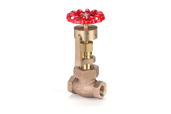
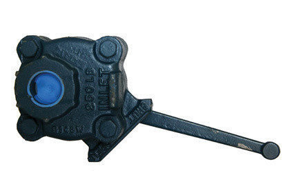
Blowdown valves come in two varieties, fast-open and slow-open. Fast-open valves act as the quick cutoff, while slow-open valves allow modulation of the water flow.
During a blowdown, the fast-open valve is opened first. This feeds the slow-open valve, which can then be opened gradually for operator safety and to prevent thermal shock to the drain pipes.
There are four locations where blowdown valves are typically installed:The bottom of the sight glassto keep water readings accurateThe bottom of the boilerto remove heavier solids, sediment, and impuritiesLevel with the surface of the water inside the boilerto allow floating impurities to be blown outThe low water cutoff, to confirm that it is operating properly
Without the blowdown valve in place, sediment and other impurities would gradually build up along the inside surface of the boiler. This would not only reduce the boiler’s operating efficiency, it could also become a safety hazard by creating uneven heating and metal stress.
Blowdown valves also regulate electrical conductivity in the boiler water by regulating the amount of suspended solids. Higher electrical conductivity creates faster scale buildup, which reduces a boiler’s operating efficiency. Higher conductivity also decreases the life of the boiler by accelerating the corrosive effects of the oxygen inside.
Things to Consider about Blowdown Valves:When the blowdown valve is opened, the water is extremely hot, and has a lot of steam pressure behind it. Always use extreme caution and be aware of your environment when operating a blowdown valve.Always wear proper protective equipment when operating a blowdown valve.Open the valve slowly. This is not only for operator safety, it also reduces thermal shock to the venting pipes.After completing a blowdown, momentarily crack the slow-open valve to release the pressure between the valves.
Distributor of hydraulic press safety, quick opening safety, rotary and safety valves. Amerigear®, Boston Gear®, Carlisle®, DeMag®, Desch® and IMI Norgren®, pneumatic, double action, quick release and flow control valves also provided. Repair and preventative maintenance services are offered. Value added services such as custom barcoding, CAD capabilities, OEM assembly, plant surveys and third party logistics are also available. Serves the metal processing, metal service center, paper mill and paper converting, canning, grinding, commercial laundry, marine, oil and gas and material handling industries. Vendor managed inventory (VMI) programs available. Kanban delivery.
Custom manufacturer of cooling water, boiler water, closed loop & heating water system treatment chemicals, coil & duct cleaners, anitfoam defoaming agents & descale products. Meets ISO 9001 standards. Distributor of water treatment equipment & supplies including defoaming agents, alarms, antennas, dual head assemblies, automation systems, blocks, chemical & static in-line mixers, chlorinators, coil cleaners, calibration columns, flow controls, sample coolers, ultraviolet (UV) sterilizers, tubing, deodorizers, chemical bypass feeders, filters, flowmeters, gages, chemical injectors, water & pulse meters, misting systems, monitoring systems, pumps, racks, refractometers, rotameters, flow sensors, solids separators, lift stations, liquid flow switches, tanks, safety equipment, test kits, testing equipment, level transmitters, thermometer wells, wireless remote controls & wireless transmitters. Training & industrial & processed water treatment services are also available.

The pressure below the valve must increase above the set pressurebefore the safety valve reaches a noticeable lift. As a result of the restriction of flow between the disc and the adjusting ring, pressure builds up in the huddling chamber. The pressure now acts on an enlarged disc area. This increases the force Fp so that the additional spring force required to further compress the spring is overcome. The valve will open rapidly with a "pop", in most cases to its full lift.
Overpressure is the pressure increase above the set pressurenecessary for the safety valve to achieve full lift and capacity. The overpressure is usually expressed as a percentage of the set pressure. Codes and standards provide limits for the maximum overpressure. A typical value is 10%, ranging between 3% and 21% depending on the code and application.

There is a wide range of safety valves available to meet the many different applications and performance criteria demanded by different industries. Furthermore, national standards define many varying types of safety valve.
The ASME standard I and ASME standard VIII for boiler and pressure vessel applications and the ASME/ANSI PTC 25.3 standard for safety valves and relief valves provide the following definition. These standards set performance characteristics as well as defining the different types of safety valves that are used:
ASME I valve - A safety relief valve conforming to the requirements of Section I of the ASME pressure vessel code for boiler applications which will open within 3% overpressure and close within 4%. It will usually feature two blowdown rings, and is identified by a National Board ‘V’ stamp.
ASME VIII valve- A safety relief valve conforming to the requirements of Section VIII of the ASME pressure vessel code for pressure vessel applications which will open within 10% overpressure and close within 7%. Identified by a National Board ‘UV’ stamp.
Full bore safety valve - A safety valve having no protrusions in the bore, and wherein the valve lifts to an extent sufficient for the minimum area at any section, at or below the seat, to become the controlling orifice.
Conventional safety relief valve -The spring housing is vented to the discharge side, hence operational characteristics are directly affected by changes in the backpressure to the valve.
Balanced safety relief valve -A balanced valve incorporates a means of minimising the effect of backpressure on the operational characteristics of the valve.
Pilot operated pressure relief valve -The major relieving device is combined with, and is controlled by, a self-actuated auxiliary pressure relief device.
Power-actuated safety relief valve - A pressure relief valve in which the major pressure relieving device is combined with, and controlled by, a device requiring an external source of energy.
Standard safety valve - A valve which, following opening, reaches the degree of lift necessary for the mass flowrate to be discharged within a pressure rise of not more than 10%. (The valve is characterised by a pop type action and is sometimes known as high lift).
Full lift (Vollhub) safety valve -A safety valve which, after commencement of lift, opens rapidly within a 5% pressure rise up to the full lift as limited by the design. The amount of lift up to the rapid opening (proportional range) shall not be more than 20%.
Direct loaded safety valve -A safety valve in which the opening force underneath the valve disc is opposed by a closing force such as a spring or a weight.
Proportional safety valve - A safety valve which opens more or less steadily in relation to the increase in pressure. Sudden opening within a 10% lift range will not occur without pressure increase. Following opening within a pressure of not more than 10%, these safety valves achieve the lift necessary for the mass flow to be discharged.
Diaphragm safety valve -A direct loaded safety valve wherein linear moving and rotating elements and springs are protected against the effects of the fluid by a diaphragm
Bellows safety valve - A direct loaded safety valve wherein sliding and (partially or fully) rotating elements and springs are protected against the effects of the fluids by a bellows. The bellows may be of such a design that it compensates for influences of backpressure.
Controlled safety valve - Consists of a main valve and a control device. It also includes direct acting safety valves with supplementary loading in which, until the set pressure is reached, an additional force increases the closing force.
Safety valve - A safety valve which automatically, without the assistance of any energy other than that of the fluid concerned, discharges a quantity of the fluid so as to prevent a predetermined safe pressure being exceeded, and which is designed to re-close and prevent further flow of fluid after normal pressure conditions of service have been restored. Note; the valve can be characterised either by pop action (rapid opening) or by opening in proportion (not necessarily linear) to the increase in pressure over the set pressure.
Direct loaded safety valve -A safety valve in which the loading due to the fluid pressure underneath the valve disc is opposed only by a direct mechanical loading device such as a weight, lever and weight, or a spring.
Assisted safety valve -A safety valve which by means of a powered assistance mechanism, may additionally be lifted at a pressure lower than the set pressure and will, even in the event of a failure of the assistance mechanism, comply with all the requirements for safety valves given in the standard.
Supplementary loaded safety valve - A safety valve that has, until the pressure at the inlet to the safety valve reaches the set pressure, an additional force, which increases the sealing force.
Note; this additional force (supplementary load), which may be provided by means of an extraneous power source, is reliably released when the pressure at the inlet of the safety valve reaches the set pressure. The amount of supplementary loading is so arranged that if such supplementary loading is not released, the safety valve will attain its certified discharge capacity at a pressure not greater than 1.1 times the maximum allowable pressure of the equipment to be protected.
Pilot operated safety valve -A safety valve, the operation of which is initiated and controlled by the fluid discharged from a pilot valve, which is itself, a direct loaded safety valve subject to the requirement of the standard.
The common characteristic shared between the definitions of conventional safety valves in the different standards, is that their operational characteristics are affected by any backpressure in the discharge system. It is important to note that the total backpressure is generated from two components; superimposed backpressure and the built-up backpressure:
Subsequently, in a conventional safety valve, only the superimposed backpressure will affect the opening characteristic and set value, but the combined backpressure will alter the blowdown characteristic and re-seat value.
The ASME/ANSI standard makes the further classification that conventional valves have a spring housing that is vented to the discharge side of the valve. If the spring housing is vented to the atmosphere, any superimposed backpressure will still affect the operational characteristics. Thiscan be seen from Figure 9.2.1, which shows schematic diagrams of valves whose spring housings are vented to the discharge side of the valve and to the atmosphere.
By considering the forces acting on the disc (with area AD), it can be seen that the required opening force (equivalent to the product of inlet pressure (PV) and the nozzle area (AN)) is the sum of the spring force (FS) and the force due to the backpressure (PB) acting on the top and bottom of the disc. In the case of a spring housing vented to the discharge side of the valve (an ASME conventional safety relief valve, see Figure 9.2.1 (a)), the required opening force is:
In both cases, if a significant superimposed backpressure exists, its effects on the set pressure need to be considered when designing a safety valve system.
Once the valve starts to open, the effects of built-up backpressure also have to be taken into account. For a conventional safety valve with the spring housing vented to the discharge side of the valve, see Figure 9.2.1 (a), the effect of built-up backpressure can be determined by considering Equation 9.2.1 and by noting that once the valve starts to open, the inlet pressure is the sum of the set pressure, PS, and the overpressure, PO.
Balanced safety valves are those that incorporate a means of eliminating the effects of backpressure. There are two basic designs that can be used to achieve this:
Although there are several variations of the piston valve, they generally consist of a piston type disc whose movement is constrained by a vented guide. The area of the top face of the piston, AP, and the nozzle seat area, AN, are designed to be equal. This means that the effective area of both the top and bottom surfaces of the disc exposed to the backpressure are equal, and therefore any additional forces are balanced. In addition, the spring bonnet is vented such that the top face of the piston is subjected to atmospheric pressure, as shown in Figure 9.2.2.
The bellows arrangement prevents backpressure acting on the upper side of the disc within the area of the bellows. The disc area extending beyond the bellows and the opposing disc area are equal, and so the forces acting on the disc are balanced, and the backpressure has little effect on the valve opening pressure.
Bellows failure is an important concern when using a bellows balanced safety valve, as this may affect the set pressure and capacity of the valve. It is important, therefore, that there is some mechanism for detecting any uncharacteristic fluid flow through the bellows vents. In addition, some bellows balanced safety valves include an auxiliary piston that is used to overcome the effects of backpressure in the case of bellows failure. This type of safety valve is usually only used on critical applications in the oil and petrochemical industries.
Since balanced pressure relief valves are typically more expensive than their unbalanced counterparts, they are commonly only used where high pressure manifolds are unavoidable, or in critical applications where a very precise set pressure or blowdown is required.
This type of safety valve uses the flowing medium itself, through a pilot valve, to apply the closing force on the safety valve disc. The pilot valve is itself a small safety valve.
The diaphragm type is typically only available for low pressure applications and it produces a proportional type action, characteristic of relief valves used in liquid systems. They are therefore of little use in steam systems, consequently, they will not be considered in this text.
The piston type valve consists of a main valve, which uses a piston shaped closing device (or obturator), and an external pilot valve. Figure 9.2.4 shows a diagram of a typical piston type, pilot operated safety valve.
The piston and seating arrangement incorporated in the main valve is designed so that the bottom area of the piston, exposed to the inlet fluid, is less than the area of the top of the piston. As both ends of the piston are exposed to the fluid at the same pressure, this means that under normal system operating conditions, the closing force, resulting from the larger top area, is greater than the inlet force. The resultant downward force therefore holds the piston firmly on its seat.
If the inlet pressure were to rise, the net closing force on the piston also increases, ensuring that a tight shut-off is continually maintained. However, when the inlet pressure reaches the set pressure, the pilot valve will pop open to release the fluid pressure above the piston. With much less fluid pressure acting on the upper surface of the piston, the inlet pressure generates a net upwards force and the piston will leave its seat. This causes the main valve to pop open, allowing the process fluid to be discharged.
When the inlet pressure has been sufficiently reduced, the pilot valve will reclose, preventing the further release of fluid from the top of the piston, thereby re-establishing the net downward force, and causing the piston to reseat.
Pilot operated safety valves offer good overpressure and blowdown performance (a blowdown of 2% is attainable). For this reason, they are used where a narrow margin is required between the set pressure and the system operating pressure. Pilot operated valves are also available in much larger sizes, making them the preferred type of safety valve for larger capacities.
One of the main concerns with pilot operated safety valves is that the small bore, pilot connecting pipes are susceptible to blockage by foreign matter, or due to the collection of condensate in these pipes. This can lead to the failure of the valve, either in the open or closed position, depending on where the blockage occurs.
The terms full lift, high lift and low lift refer to the amount of travel the disc undergoes as it moves from its closed position to the position required to produce the certified discharge capacity, and how this affects the discharge capacity of the valve.
A full lift safety valve is one in which the disc lifts sufficiently, so that the curtain area no longer influences the discharge area. The discharge area, and therefore the capacity of the valve are subsequently determined by the bore area. This occurs when the disc lifts a distance of at least a quarter of the bore diameter. A full lift conventional safety valve is often the best choice for general steam applications.
The disc of a high lift safety valve lifts a distance of at least 1/12th of the bore diameter. This means that the curtain area, and ultimately the position of the disc, determines the discharge area. The discharge capacities of high lift valves tend to be significantly lower than those of full lift valves, and for a given discharge capacity, it is usually possible to select a full lift valve that has a nominal size several times smaller than a corresponding high lift valve, which usually incurs cost advantages.Furthermore, high lift valves tend to be used on compressible fluids where their action is more proportional.
In low lift valves, the disc only lifts a distance of 1/24th of the bore diameter. The discharge area is determined entirely by the position of the disc, and since the disc only lifts a small amount, the capacities tend to be much lower than those of full or high lift valves.
Except when safety valves are discharging, the only parts that are wetted by the process fluid are the inlet tract (nozzle) and the disc. Since safety valves operate infrequently under normal conditions, all other components can be manufactured from standard materials for most applications. There are however several exceptions, in which case, special materials have to be used, these include:
Cast steel -Commonly used on higher pressure valves (up to 40 bar g). Process type valves are usually made from a cast steel body with an austenitic full nozzle type construction.
For all safety valves, it is important that moving parts, particularly the spindle and guides are made from materials that will not easily degrade or corrode. As seats and discs are constantly in contact with the process fluid, they must be able to resist the effects of erosion and corrosion.
The spring is a critical element of the safety valve and must provide reliable performance within the required parameters. Standard safety valves will typically use carbon steel for moderate temperatures. Tungsten steel is used for higher temperature, non-corrosive applications, and stainless steel is used for corrosive or clean steam duty. For sour gas and high temperature applications, often special materials such as monel, hastelloy and ‘inconel’ are used.
Standard safety valves are generally fitted with an easing lever, which enables the valve to be lifted manually in order to ensure that it is operational at pressures in excess of 75% of set pressure. This is usually done as part of routine safety checks, or during maintenance to prevent seizing. The fitting of a lever is usually a requirement of national standards and insurance companies for steam and hot water applications. For example, the ASME Boiler and Pressure Vessel Code states that pressure relief valves must be fitted with a lever if they are to be used on air, water over 60°C, and steam.
A test gag (Figure 9.2.7) may be used to prevent the valve from opening at the set pressure during hydraulic testing when commissioning a system. Once tested, the gag screw is removed and replaced with a short blanking plug before the valve is placed in service.
The amount of fluid depends on the particular design of safety valve. If emission of this fluid into the atmosphere is acceptable, the spring housing may be vented to the atmosphere – an open bonnet. This is usually advantageous when the safety valve is used on high temperature fluids or for boiler applications as, otherwise, high temperatures can relax the spring, altering the set pressure of the valve. However, using an open bonnet exposes the valve spring and internals to environmental conditions, which can lead to damage and corrosion of the spring.
When the fluid must be completely contained by the safety valve (and the discharge system), it is necessary to use a closed bonnet, which is not vented to the atmosphere. This type of spring enclosure is almost universally used for small screwed valves and, it is becoming increasingly common on many valve ranges since, particularly on steam, discharge of the fluid could be hazardous to personnel.
Some safety valves, most commonly those used for water applications, incorporate a flexible diaphragm or bellows to isolate the safety valve spring and upper chamber from the process fluid, (see Figure 9.2.9).
In order to ensure that the maximum allowable accumulation pressure of any system or apparatus protected by a safety valve is never exceeded, careful consideration of the safety valve’s position in the system has to be made. As there is such a wide range of applications, there is no absolute rule as to where the valve should be positioned and therefore, every application needs to be treated separately.
A common steam application for a safety valve is to protect process equipment supplied from a pressure reducing station. Two possible arrangements are shown in Figure 9.3.3.
The safety valve can be fitted within the pressure reducing station itself, that is, before the downstream stop valve, as in Figure 9.3.3 (a), or further downstream, nearer the apparatus as in Figure 9.3.3 (b). Fitting the safety valve before the downstream stop valve has the following advantages:
• The safety valve can be tested in-line by shutting down the downstream stop valve without the chance of downstream apparatus being over pressurised, should the safety valve fail under test.
• When setting the PRV under no-load conditions, the operation of the safety valve can be observed, as this condition is most likely to cause ‘simmer’. If this should occur, the PRV pressure can be adjusted to below the safety valve reseat pressure.
Indeed, a separate safety valve may have to be fitted on the inlet to each downstream piece of apparatus, when the PRV supplies several such pieces of apparatus.
• If supplying one piece of apparatus, which has a MAWP pressure less than the PRV supply pressure, the apparatus must be fitted with a safety valve, preferably close-coupled to its steam inlet connection.
• If a PRV is supplying more than one apparatus and the MAWP of any item is less than the PRV supply pressure, either the PRV station must be fitted with a safety valve set at the lowest possible MAWP of the connected apparatus, or each item of affected apparatus must be fitted with a safety valve.
• The safety valve must be located so that the pressure cannot accumulate in the apparatus viaanother route, for example, from a separate steam line or a bypass line.
It could be argued that every installation deserves special consideration when it comes to safety, but the following applications and situations are a little unusual and worth considering:
• Fire - Any pressure vessel should be protected from overpressure in the event of fire. Although a safety valve mounted for operational protection may also offer protection under fire conditions,such cases require special consideration, which is beyond the scope of this text.
• Exothermic applications - These must be fitted with a safety valve close-coupled to the apparatus steam inlet or the body direct. No alternative applies.
• Safety valves used as warning devices - Sometimes, safety valves are fitted to systems as warning devices. They are not required to relieve fault loads but to warn of pressures increasing above normal working pressures for operational reasons only. In these instances, safety valves are set at the warning pressure and only need to be of minimum size. If there is any danger of systems fitted with such a safety valve exceeding their maximum allowable working pressure, they must be protected by additional safety valves in the usual way.
In order to illustrate the importance of the positioning of a safety valve, consider an automatic pump trap (see Block 14) used to remove condensate from a heating vessel. The automatic pump trap (APT), incorporates a mechanical type pump, which uses the motive force of steam to pump the condensate through the return system. The position of the safety valve will depend on the MAWP of the APT and its required motive inlet pressure.
This arrangement is suitable if the pump-trap motive pressure is less than 1.6 bar g (safety valve set pressure of 2 bar g less 0.3 bar blowdown and a 0.1 bar shut-off margin). Since the MAWP of both the APT and the vessel are greater than the safety valve set pressure, a single safety valve would provide suitable protection for the system.
Here, two separate PRV stations are used each with its own safety valve. If the APT internals failed and steam at 4 bar g passed through the APT and into the vessel, safety valve ‘A’ would relieve this pressure and protect the vessel. Safety valve ‘B’ would not lift as the pressure in the APT is still acceptable and below its set pressure.
It should be noted that safety valve ‘A’ is positioned on the downstream side of the temperature control valve; this is done for both safety and operational reasons:
Operation - There is less chance of safety valve ‘A’ simmering during operation in this position,as the pressure is typically lower after the control valve than before it.
Also, note that if the MAWP of the pump-trap were greater than the pressure upstream of PRV ‘A’, it would be permissible to omit safety valve ‘B’ from the system, but safety valve ‘A’ must be sized to take into account the total fault flow through PRV ‘B’ as well as through PRV ‘A’.
A pharmaceutical factory has twelve jacketed pans on the same production floor, all rated with the same MAWP. Where would the safety valve be positioned?
One solution would be to install a safety valve on the inlet to each pan (Figure 9.3.6). In this instance, each safety valve would have to be sized to pass the entire load, in case the PRV failed open whilst the other eleven pans were shut down.
If additional apparatus with a lower MAWP than the pans (for example, a shell and tube heat exchanger) were to be included in the system, it would be necessary to fit an additional safety valve. This safety valve would be set to an appropriate lower set pressure and sized to pass the fault flow through the temperature control valve (see Figure 9.3.8).
![]()
meets numerous application requirements. For example. the type 1900-UM valve is capable of flowing liquid, gas or steam with no adjustment required to switch between different media with the same set pressure.
The ConsolidatedType 19000valve is ASME and PED certified. It meets and exceeds API seat tightness performance. The 19000 offers enhanced capacity and blowdown performance on many media types. In most cases, it does not require parts changes to accommodate different media.
choice for OEM and skid manufacturers requiring high-relief capacity from a small valve. The 1982 offers superior seat tightness and blowdown performance for most media applications.
The ConsolidatedType 11000Series Safety Relief Valve combines performance, quality, reliability and value into a single overpressure device. The 11000 SRV is specifically designed for the most demanding upstream and midstream oil and gas applications where safety is of prime importance.
“4Matic” Blowdown valves are used to drain some amount of liquid from an equipment. It is attached to those equipment whose working fluids contain solid impurities. The nature of such impurities are that they don’t dissolve in the working fluid and it may get deposited on the surfaces of the equipment this causing problems in the operation of the equipment.
A spring-loaded relief valve can be thought of as a spring /mass system which is why relief valves chatter. Researchers have found significant differences in the stability of relief valves based on the design of their internals. One recent study found that with 6 feet of inlet piping, valves from Manufacturer X were stable in 50% of the tests while valves from Manufacturer Z where stable in 100% of these tests.¹ Smith & Burgess Laboratory research has confirmed these findings. However, relief systems designers tend to downplay (if not ignore) the importance of the mechanical design of relief valves which is important to stability. Therefore, this article discusses the fundamentals of the design parameters for the internals of a relief valve. The intent is to provide design considerations and general operation information for use by relief systems designers, specifically assisting with the understanding of the effects of valve design on stability.
Modern relief valves are wonderfully modular.The internal parts for a relief valve (valve disc,disc holder, blowdown ringandspring) can be interchanged for ones with a different design to customize valve performance based on the application, fluid service, and set pressure.Valve disccan be metal-to-metal or soft seats. Soft seat designs use an elastomer to create a better seal between thevalvediscand thenozzle. Relief valves with elastomer seats have limitations and can only be used in certain applications.Disc holdersare generally designed to allow thevalve discto float which provides an angular movement that reduces seat leakage from minor misalignments (ensuring that thevalve dischas 360 degrees of contact with thenozzle). Thedisc holderoutside diameter, shape and thickness plays an important role in determining the valve performance by defining the shape of thehuddling chamber. Thehuddling chambercan also be defined by theblowdown ring(s). Thering(s)can also be swapped to different sized and shapedringsto adjust performance based on the expected relief fluid.Springsare selected to keep the valve closed and must fit inside thevalve bonnet. The force thespringexerts is an important design criteria for a relief device and varies depending on the relief fluid, valve size and set pressure.
Spring loaded relief valves are known as "pop action" relief valves as they typically pop open at their set pressure. Initially, the pressure differential across thevalve discthat creates the force to over come the spring force and open the valve.The pop action occurs because mosthuddling chambersare designed with an area that is approximately 10%-30% larger than thevalve seat(as thedisc holderis bigger than thevalve disc). Once the pressure under the seat is enough to lift thevalve discoff thenozzle, there is a step change in the upward forces on thespringand the valve "pops" open. The shape of thehuddling chamber(created by the shape and size of thedisc holder), the position and shape of theblowdown ring, and the characteristics of the fluid being relieved together determine the initial opening force and the initial lift of the valve.
Blowdown ringsare adjustable rings with a design shape that modifies the effluent flow path andhuddling chamberbased on the position. For process valves, a singleblowdown ringis typically threaded onto thenozzleand can be adjusted vertically up or down. Manufacturers will specify a recommended position relative to contact with thevalve disc. The position of theblowdown ringis fixed with a locking screw. The position of theblowdown ringchanges the blowdown (or reseat) pressure. For valves with a singleblowdown ring, the closer theblowdown ringis to thenozzle, the lower the pressure in the system will need to be for the valve to close (more blowdown). Other relief valves have multipleblowdown rings. Each manufacturer designs a uniqueblowdown ringto compliment other aspects of the relief valve design. Smith & Burgess" testing confirms that position and design ofblowdown ring(s)affects valve stability.
Relief Valve manufactures generally select aspringthat is designed for the set pressure of the valve. Thespringthat is selected will have a pressure range that thespringcan be applied. In many cases, there may be more than onespringthat can be used with each relief valve each having a different spring constant. The stifferspringmay have a range that is higher than the softerspringbut still meet the overall requirements for set pressure. The selection of thespringwill affect stability as the specific spring influences the natural frequency of the valve and can also affect the blowdown.

Manufacturer of a wide range of products which include boiler safety valve, safety valve-pop type, pressure safety valve, spring loaded safety valve, safety relief valve and ibr safety valve.
ConnectionThreaded and Flanged EndsWe are the manufacturer, Supplier, and Exporter of Boiler Safety Valve from Chennai -India to Globally. These Safety Valves are Used to release the excess pressure inside the Boiler, High-Pressure Tanks, nd Vessels. So that Pressure can be maintained uniformly. we are manufacturer of valves like: Pressure Relief Valves, Safety relief Valves, Vacuum Relief Valve, Pressure cum vacuum relief valve, Breather valves.
Certificate-ApprovalISO, IBR, IRS, ATEX, TUV, BV, SGSWe are the manufacturer, supplier, and exporter of Safety Valves from Chennai-India to Globally. Used for controlling excess pressures, their precision construction standards make them extensively used in equipment like pressure vessels, pipelines & reactors.We have good infrastructure facility for EXPORT
LeverPlain and Packed LeverBEEKAY brand Safety Valve, Safety Relief Valve, pressure Safety Valves are manufactured by LEVEL AND FLOW CONTROL ENGINEERS in India. Pressure Safety Valve can safeguard the tanks, vessels, boilers, and other capital equipments. when the pressure is esceed the limit valve will open automatically and release the excess pressure.we are expecting enquiry and orders from all over the world.
Accumulation0 to 10%LFCE Spring Loaded Safety Valve, Safety Relief Valves and Pressure Relief Valves are high performance and cost effective. Based on client request we can ready to supply valves with 0 to 5% accumulation and blowdown.Valve size : 1/4" to 12"
Country of OrginIndiaBEEKAY brand Safety Valve, Safety Relief Valve are manufactured by Level and Flow Control Engineers in INDIA. Valves are 100% safe and accuracy for Set pressure and Re-set pressures. Valves are mounted on pipelines, tanks, vessels and reactors to safeguard the capital equipments.We have already exported our range of products to all over the world like UAE, Middle East, Germany, Italay, Australlia, Malysia, Thailand, Indonesia, Philipines, Burunei, Srilanka, Pakistan, Netherland and many more
Flange Ratings150, 300, 600, 900, 1500 lbs RatingsLFCE Manufacturing, supplying, Exporting IBR Certified Safety Valves for Boilers, Deareators, LP, HP Heaters, Condensate Tanks and Vessels. We can able to supply the valves size from 25NB to 300NB and the Pressure Rating 150 lbs to 1500 lbs
We are expecting enquiry and orders from all over the world. Our valves and range of products are well exported to UAE, MIddle East, Thailand, Indonesia, Mayanmar, Vietnam, Srilanka, Malaysia, Singapore, Philipines, Australlia, Netherland, Italy, UAE, South African Countires.
Country of OriginMade in IndiaLFCE manufacturing, supplying, EXPORTING Safety Valve, Pressure Relief Valves with Lever and Plain types.We can able to supply CS, SS, DSS, SDSS, Alloy Steel grade of Materials with Max. of Pressure of 150 barValve size from 15NB to 200NBWe are expecting good enquiry and orders from all over the globe.
Rust ResistanceYesLFCE manufacturing and supplying Beekay brand Brass Safety Valves, Safety Relief Valves, Pressure Relief Valves fo the pressure vessels and Air Receivers. When the pressure is exceed the limit then the valve will open automatically and safeguard the capital equipments.Our brand Beekay is well known in the global market. Already we exported our range of products to all over the world :- UAE, Middle East, South Africa, Zimbawe, Zambia, Kenya, Oman, Saudi Arabia, Thailand, Indonesia, Philipines, Burunei, Srilanka, Pakistan, Hongkong, Netherland, Italay and many more
Flange StandardsANSI, BS, DIN, JS, IS, ASMELFCE manufacturing and EXPORTING Low Pressure, Medium Pressure, High Pressure Safety Valves, Safety Relief Valves for the Process Industries and Hydro Carbon Projects.Our Valves are manufactured and tested as per API StandardsWe are expecting enquiry/orders from all over the world.
The primary purpose of a blowdown valve is to regulate a constant flow of steam/fluid at an elevated differential pressure and also to remove dirt, sediment, and limescale.
Blowdown valves are used either continuously or intermittently depending on the service requirements and play an important role in fossil fuel boilers to remove dissolved solids from the boiler water. Generally, only one blowdown valve is used in a boiler. If more than one blowdown valve is used in a boiler, the two valves are often used in series to minimize erosion. In this design, one valve acts as the shutoff valve, and the other valve acts as the drain valve. The shutoff valve is usually opened first and closed last. To minimize erosion of the disc and seat, both valves are opened quickly and simultaneously. Most importantly, care should be taken to avoid trapping rust particles in the valve during the drainage process. This is accomplished by opening the valves again so that any remaining rust particles are flushed out with the next passage of steam through the piping. Whenever a boiler is taken out of service for maintenance, the bottom drain valve is usually rebuilt or replaced.
Generally, we classify blowdown valves into two categories, continuous blowdown(CBD) valves, and intermittent blowdown (IBD) valves, since the intermittent blowdown valve works close to the bottom of the boiler, we also call it a bottom blowdown valve.
The continuous blowdown valve (CBD) is designed to operate in a constant open position to maintain the TDS level in the boiler ladle by continuously releasing water from the boiler water surface through the blowdown tap. Some engineers also name this valve a surface blowdown valve.
The purpose of the bottom blowdown valve is to remove boiler sediment to keep the boiler water in compliance with manufacturing standards to improve the efficiency and performance of the boiler.
The function of the intermittent blowdown valve is to release accumulated sludge and sewage through a drain near the bottom of the boiler at regular periods, usually with a predetermined time cycle. There is a special requirement for the bottom blowdown valve to ensure that the valve can be tightly closed after repeated draining actions.
In boiler operation, the deposition of impurities is highest at the point where liquid water is converted to steam. The resulting scale forms an insulating layer, impeding the flow of heat through the equipment. As the thickness of the formed scale increases, the rate of steam generation decreases, as does the rate of heat flow. In addition, due to the accumulation of heat, the temperature of the metal surface may increase to the point where the metal surface itself may be damaged. Generally, drain valves are installed on equipment in processes where the working fluid is water. If the water contains solid impurities and some of the water continues to evaporate through some mechanism, such as drafting in a cooling tower or vaporization in a boiler, then the concentration of solid impurities in other water that accumulates in the equipment increases. Drain valves are used to drain a certain amount of liquid from equipment that contains solid impurities that by their nature are insoluble in the working fluid and may be deposited on the surface of the equipment, causing problems with the operation of the equipment.
If the water in the boiler is not well treated in the preparation stage, the density of insoluble substances (TDS) will increase due to steam generation. If the determined limit is exceeded, it can cause damage to the boiler and piping, and eventually lead to equipment failure. Insoluble materials are carried along with steam, and they can increase the conductivity of condensate and cause energy loss. Insoluble materials typically include calcium and magnesium salts, and these insoluble substances are deposited during the steam production process, and we need to remove them through a number of techniques to achieve optimum TDS levels. This operation is known as blowdown, and the valve used for this purpose is known as a blowdown valve.
Continuous blowdown: Also called surface blowdown, it is a continuous process of draining the most concentrated furnace water from the surface layer of the steam ladle furnace water. The purpose is to reduce the salinity and alkalinity of the boiler water to prevent the concentration of the furnace water from being too high and affecting the quality of steam. Continuous drain is generally installed in the steam ladle normal water level (i.e. “0” level) 80-100mm below. Furnace water is continuously evaporated and concentrated so that the highest concentration of salt is near the water surface. Therefore, the continuous drainage orifice should be installed in the area with the highest density of furnace water, in order to continuously discharge high-density furnace water and supplement it with clean feed water, so as to improve the quality of boiler water, and the drainage rate is generally about 1% of the evaporation volume.
The drain valve usually uses a gate valve or globe valve. The nominal diameter of the drain valve is DN25~50, rated evaporation ≥1t/h or working pressure ≥0.7Mpa boiler, the drain pipe should be installed with two drain valves in series.
The traditional design is a combination of 1 slow drain (with gate valve) + 1 fast drain (high-temperature ball valve), but due to the PTFE soft seal inside the ball valve, the valve seat is easily deformed by aging due to the long-term high temperature above 140℃, which eventually leads to valve leakage. And the gate valve sealing groove is easy to accumulate impurities, the gate does not close tightly and leaks. So this design service life is short.
Use one slow discharge (with bellows shut off globe valve S25FGB) + one fast discharge (quick-opening bellows shut-off valve S25F). The quick opening bellows globe valve S25FGB-1 is a special replacement for the high-temperature ball valve.
Advantages The switch is fast and convenient, only needs to make within 180 ℃ rotation, you can achieve from fully open to fully closed or fully closed to fully open, and the sealing performance of the globe valve, as well as the quick switching performance of the ball valve.
When discharging, the blowdown valve is subjected to high-temperature liquid flushing and dirt wear and will be cooled to room temperature after it stops draining. In order to improve the drain valve’s frequent poor working conditions such as pressure difference (large differential pressure drop), scale corrosion and wear vibration, and thermal shock,the series drain valve has a certain operation procedure: when discharging, valve 1 (slow opening blowdown valve) is opened first, then valve 2 (quick opening blowdown valve) is opened; when stopping discharging, valve 2 is closed first, then valve 1 is closed.
Valve 1 is a slow-opening blowdown valve, which should have the ability to resist alkaline corrosion of furnace water; valve 2 is a fast-opening blowdown valve, which should meet the action and time requirements of drainage.
THINKTANKis a reliableblowdown valve supplier, manufacturerand factory, with rich experience in replacing international brands for boiler manufacturers and end-users. If you have any related questions about blowdown valves, please feel free to contact us. We are here willing to provide expert service for you.

Safety Relief ValvePioneers in the industry, we offer safety relief valve, pressure safety valve, thermal relief valve, sanitary safety valve, flange end safety relief valve and high pressure relief valve from India.

A customer has requested an accumulation of less than 10% for relief valves. We are unfamiliar with the term "accumulation" in this context. The customer defines it as the pressure difference when the relief valve starts relieving and the pressure when the valve is fully open. This makes no sense to us, as this ratio would change with the relief valve setting. Any insights?
Accumulation is the overpressure between when the valve initially opens and where its capacity is rated. This is defined by the ASME Boiler and Pressure Vessel code, which is recognized as law by most states. ASME Section VIII safety-relief valves reach rated capacity at 10% accumulation, and generally reclose on 10% blowdown, or 10% below initial set pressure. Sec VIII valves are intended for non-fired pressure vessels. ASME section 1 Safety valves operate with 3% accumulation. Sec 1 valves are for fired pressure vessels (boilers) The ratio does NOT change with relief valve setting. The springs used for setting a relief valve have a very narrow range. You can"t just crank down on the adjuster or a 50 psi valve and reset it to 100 psi. Spring-operated safety-relief valves may need the overpressure to operate stably. You might get away better with limited accumulation if you offer a pilot-operated safety-relief valve. The valve-manufacturer will de-rate the capacity if the accumulation is less than 10%.


 8613371530291