boiler safety valve diagram for sale

It is found on the majority of espresso machine boilers, but there are exceptions, such as Pavoni, Rancilio and few others. As it is a non-returnable item, please measure yours before ordering.

Choose these valves for small steam-heating boilers requiring pressure relief between 5 psi and 12 psi. They spring fully open at the set pressure and remain open until the system pressure is restored below the set pressure. All have a bronze body for durability and a long service life.

Choose these valves for small steam-heating boilers requiring pressure relief between 5 psi and 12 psi. They spring fully open at the set pressure and remain open until the system pressure is restored below the set pressure. All have a bronze body for durability and a long service life.

Years ago, it was not uncommon to read news about tragic boiler explosions, sometimes resulting in mass destruction. Today, boilers are equipped with important safety devises to help protect against these types of catastrophes. Let’s take a look at the most critical of these devices: the safety valve.
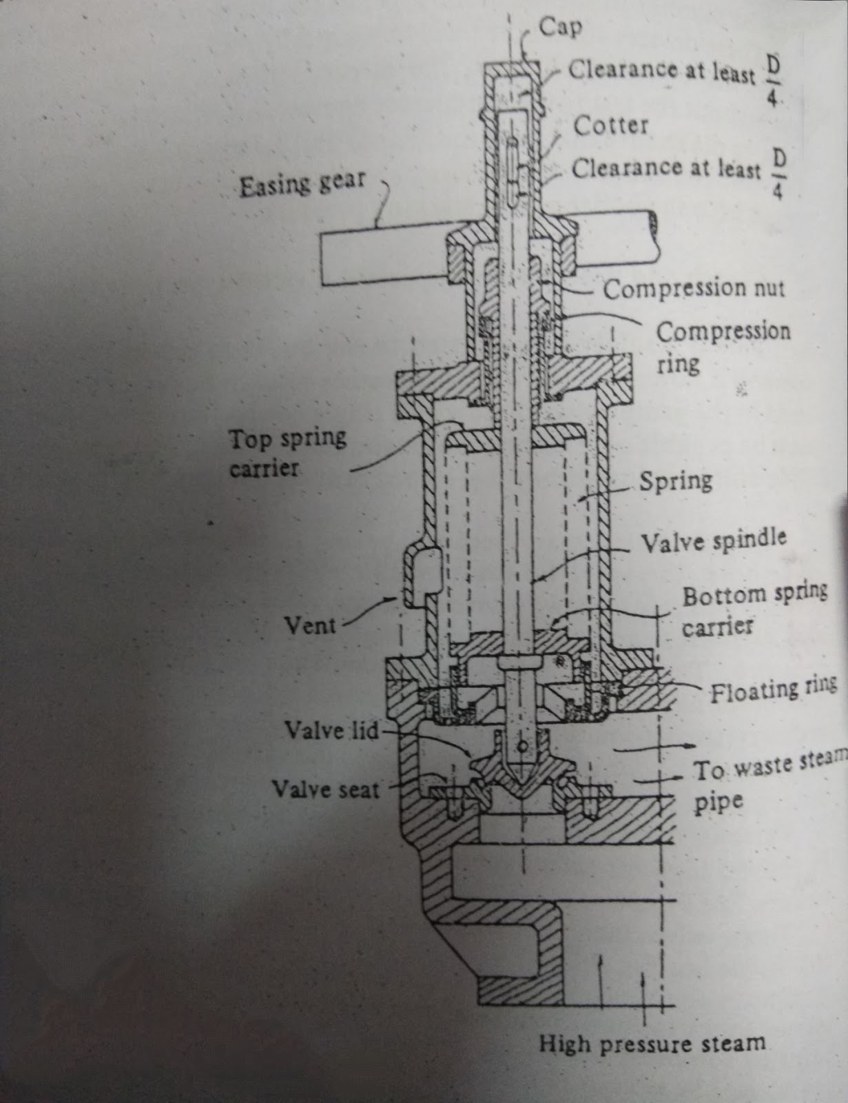
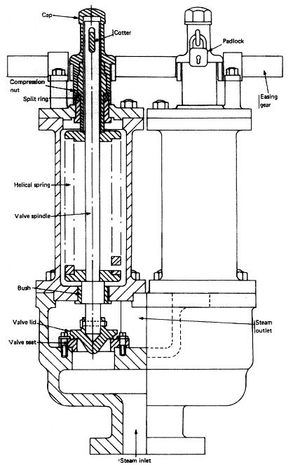
The safety valve is one of the most important safety devices in a steam system. Safety valves provide a measure of security for plant operators and equipment from over pressure conditions. The main function of a safety valve is to relieve pressure. It is located on the boiler steam drum, and will automatically open when the pressure of the inlet side of the valve increases past the preset pressure. All boilers are required by ASME code to have at least one safety valve, dependent upon the maximum flow capacity (MFC) of the boiler. The total capacity of the safety valve at the set point must exceed the steam control valve’s MFC if the steam valve were to fail to open. In most cases, two safety valves per boiler are required, and a third may be needed if they do not exceed the MFC.
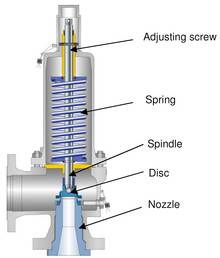
There are three main parts to the safety valve: nozzle, disc, and spring. Pressurized steam enters the valve through the nozzle and is then threaded to the boiler. The disc is the lid to the nozzle, which opens or closes depending on the pressure coming from the boiler. The spring is the pressure controller.
As a boiler starts to over pressure, the nozzle will start to receive a higher pressure coming from the inlet side of the valve, and will start to sound like it is simmering. When the pressure becomes higher than the predetermined pressure of the spring, the disc will start to lift and release the steam, creating a “pop” sound. After it has released and the steam and pressure drops below the set pressure of the valve, the spring will close the disc. Once the safety valve has popped, it is important to check the valve to make sure it is not damaged and is working properly.
A safety valve is usually referred to as the last line of safety defense. Without safety valves, the boiler can exceed it’s maximum allowable working pressure (MAWP) and not only damage equipment, but also injure or kill plant operators that are close by. Many variables can cause a safety valve on a boiler to lift, such as a compressed air or electrical power failure to control instrumentation, or an imbalance of feedwater rate caused by an inadvertently shut or open isolation valve.
Once a safety valve has lifted, it is important to do a complete boiler inspection and confirm that there are no other boiler servicing issues. A safety valve should only do its job once; safety valves should not lift continuously. Lastly, it is important to have the safety valves fully repaired, cleaned and recertified with a National Board valve repair (VR) stamp as required by local code or jurisdiction. Safety valves are a critical component in a steam system, and must be maintained.
All of Nationwide Boiler’s rental boilers include on to two safety valves depending on the size; one set at design pressure and the other set slightly higher than design. By request, we can reset the safeties to a lower pressure if the application requires it. In addition, the valves are thoroughly checked after every rental and before going out to a new customer, and they are replaced and re-certified as needed.

Boiler explosions have been responsible for widespread damage to companies throughout the years, and that’s why today’s boilers are equipped with safety valves and/or relief valves. Boiler safety valves are designed to prevent excess pressure, which is usually responsible for those devastating explosions. That said, to ensure that boiler safety valves are working properly and providing adequate protection, they must meet regulatory specifications and require ongoing maintenance and periodic testing. Without these precautions, malfunctioning safety valves may fail, resulting in potentially disastrous consequences.
Boiler safety valves are activated by upstream pressure. If the pressure exceeds a defined threshold, the valve activates and automatically releases pressure. Typically used for gas or vapor service, boiler safety valves pop fully open once a pressure threshold is reached and remain open until the boiler pressure reaches a pre-defined, safe lower pressure.
Boiler relief valves serve the same purpose – automatically lowering boiler pressure – but they function a bit differently than safety valves. A relief valve doesn’t open fully when pressure exceeds a defined threshold; instead, it opens gradually when the pressure threshold is exceeded and closes gradually until the lower, safe threshold is reached. Boiler relief valves are typically used for liquid service.
There are also devices known as “safety relief valves” which have the characteristics of both types discussed above. Safety relief valves can be used for either liquid or gas or vapor service.
Nameplates must be fastened securely and permanently to the safety valve and remain readable throughout the lifespan of the valve, so durability is key.
The National Board of Boiler and Pressure Vessel Inspectors offers guidance and recommendations on boiler and pressure vessel safety rules and regulations. However, most individual states set forth their own rules and regulations, and while they may be similar across states, it’s important to ensure that your boiler safety valves meet all state and local regulatory requirements.
The National Board published NB-131, Recommended Boiler and Pressure Vessel Safety Legislation, and NB-132, Recommended Administrative Boiler and Pressure Vessel Safety Rules and Regulationsin order to provide guidance and encourage the development of crucial safety laws in jurisdictions that currently have no laws in place for the “proper construction, installation, inspection, operation, maintenance, alterations, and repairs” necessary to protect workers and the public from dangerous boiler and pressure vessel explosions that may occur without these safeguards in place.
The American Society of Mechanical Engineers (ASME) governs the code that establishes guidelines and requirements for safety valves. Note that it’s up to plant personnel to familiarize themselves with the requirements and understand which parts of the code apply to specific parts of the plant’s steam systems.
High steam capacity requirements, physical or economic constraints may make the use of a single safety valve impossible. In these cases, using multiple safety valves on the same system is considered an acceptable practice, provided that proper sizing and installation requirements are met – including an appropriately sized vent pipe that accounts for the total steam venting capacity of all valves when open at the same time.
The lowest rating (MAWP or maximum allowable working pressure) should always be used among all safety devices within a system, including boilers, pressure vessels, and equipment piping systems, to determine the safety valve set pressure.
Avoid isolating safety valves from the system, such as by installing intervening shut-off valves located between the steam component or system and the inlet.
Contact the valve supplier immediately for any safety valve with a broken wire seal, as this indicates that the valve is unsafe for use. Safety valves are sealed and certified in order to prevent tampering that can prevent proper function.
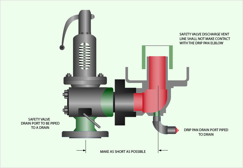
Avoid attaching vent discharge piping directly to a safety valve, which may place unnecessary weight and additional stress on the valve, altering the set pressure.

A blowdown valve’s main function is to control a continuous or intermittent flow of steam or fluid under high differential pressure. When installed in a system, they drain solid contaminants from the fluid. In this article, you will learn the working principle of a blowdown valve, review a blowdown valve diagram, and its use in boiler and compressor applications.
In industry, blowdown valves often attach to equipment where water is the working fluid. Usually, this water contains suspended solid impurities. As mechanisms such as vaporization or drafting occur in the system, the concentration of undissolved solids increases and hampers system performance. How? Some of these deposits may accumulate and form blockages that disrupt the flow. Also, the solids could deposit on the surface of the equipment and impact heat transfer. This reduces the efficiency of heat exchangers and designed cooling measures. Thus, blowdown valves along drain lines allow for the removal of these contaminants.
It is a common practice to use two blowdown valves in series. One acts as the seal valve, while the other is the main blowdown valve. Customarily, the seal valve opens first when draining, and closes last. However, to minimize erosion of the valve disk faces and seats, both may open simultaneously and rapidly.
In addition, care should be taken to avoid trapping scale and rust particles within the valve by briefly reopening it, after it has been shut. Especially if there was resistance when closing it initially. One important parameter in the operation of blowdown valves is the blowdown percentage. It refers to the ratio of the quantity of blowdown water (Vblowdown) to that of the feedwater (Vfeed) as the formula below shows.
The classification of blowdown valves depends on either the valve location or working interval. Generally, blowdown valves are installed at the surface or the bottom of the equipment, depending on the speed of solid impurities precipitation. Also, the valve may operate continuously or intermittently. Usually, surface blowdown valves operate in steady state, while bottom blowdown valves work intermittently.
This is suitable for applications where the rate of solid impurities precipitation is relatively slower. For a simple design of this type of valve, a pipe inserts near the surface of the water level. Then, water, along with impurities, goes through the pipe continuously as the valve is normally in the open position.
On the other hand, a more sophisticated design uses a swivel joint with a short length of pipe suspended on a float. Thus, it removes oil floating on the water surface. Typically, surface blowdown valves find use in equipment where a significant amount of vaporization exists. This is because as vaporization occurs, the contaminants, precipitate and remain on the water surface. Also, the outlet of these valves often feeds into a flash tank and provides heating for heat exchangers.
As the name implies, this type of blowdown valves installs at the bottom of the equipment. They are opened periodically to enable the evacuation of accumulated solid impurities and sludge. Unlike the surface blowdown valve, this type does not operate in a steady state. This is because prolonged opening decreases the water level quickly, thereby risking a shutdown of the equipment. A basic requirement of this valve is to provide tight shut-off even after repetitive blowdown operations. Also, the drainpipe diameter should be large enough so that the slug does not clog and block the flow.
The diagram above is that of a manually operated blowdown valve. Of importance, the orifice maintains fluid velocity below levels that could damage the trim. Also, the stem mates to the orifice for proper control, while the open yoke enables the operator to see the position of the plunger in the valve body. A long stroke length of the stem enables the prevention of water hammer, which occurs if the valve is opened or closed too quickly. At the exit, the angle of the orifice is intentionally made divergent, to minimize downstream piping erosion and noise.
Blowdown valves are common in boiler and compressor systems. In compressors, they serve to depressurize the gas in the system at critical times such as shutdown, restart, or in the case of an emergency. In boilers, they see more frequent use, where there could be both bottom blowdown valves, and a surface valve, in some cases.
Generally, in boilers, blowdown valves remove both suspended solids and sludge from the surface and bottom respectively. As a result, it prevents the foaming at the water surface which leads to unstable water levels and excessive passing on of liquid in the steam. When blowdown water leaves a boiler, it does so at high temperatures, creating a safety concern. For example, a boiler working at 100 psig typically discharges around 338 ℉. Thus, engineers must ensure controlled discharge occurs into a flash tank prior to disposal into drainage. Or, engineers may repurpose the heat elsewhere within the facility, perhaps to increase feedwater temperature.

As soon as mankind was able to boil water to create steam, the necessity of the safety device became evident. As long as 2000 years ago, the Chinese were using cauldrons with hinged lids to allow (relatively) safer production of steam. At the beginning of the 14th century, chemists used conical plugs and later, compressed springs to act as safety devices on pressurised vessels.
Early in the 19th century, boiler explosions on ships and locomotives frequently resulted from faulty safety devices, which led to the development of the first safety relief valves.
In 1848, Charles Retchie invented the accumulation chamber, which increases the compression surface within the safety valve allowing it to open rapidly within a narrow overpressure margin.
Today, most steam users are compelled by local health and safety regulations to ensure that their plant and processes incorporate safety devices and precautions, which ensure that dangerous conditions are prevented.
The principle type of device used to prevent overpressure in plant is the safety or safety relief valve. The safety valve operates by releasing a volume of fluid from within the plant when a predetermined maximum pressure is reached, thereby reducing the excess pressure in a safe manner. As the safety valve may be the only remaining device to prevent catastrophic failure under overpressure conditions, it is important that any such device is capable of operating at all times and under all possible conditions.
Safety valves should be installed wherever the maximum allowable working pressure (MAWP) of a system or pressure-containing vessel is likely to be exceeded. In steam systems, safety valves are typically used for boiler overpressure protection and other applications such as downstream of pressure reducing controls. Although their primary role is for safety, safety valves are also used in process operations to prevent product damage due to excess pressure. Pressure excess can be generated in a number of different situations, including:
The terms ‘safety valve’ and ‘safety relief valve’ are generic terms to describe many varieties of pressure relief devices that are designed to prevent excessive internal fluid pressure build-up. A wide range of different valves is available for many different applications and performance criteria.
In most national standards, specific definitions are given for the terms associated with safety and safety relief valves. There are several notable differences between the terminology used in the USA and Europe. One of the most important differences is that a valve referred to as a ‘safety valve’ in Europe is referred to as a ‘safety relief valve’ or ‘pressure relief valve’ in the USA. In addition, the term ‘safety valve’ in the USA generally refers specifically to the full-lift type of safety valve used in Europe.
Pressure relief valve- A spring-loaded pressure relief valve which is designed to open to relieve excess pressure and to reclose and prevent the further flow of fluid after normal conditions have been restored. It is characterised by a rapid-opening ‘pop’ action or by opening in a manner generally proportional to the increase in pressure over the opening pressure. It may be used for either compressible or incompressible fluids, depending on design, adjustment, or application.
Safety valves are primarily used with compressible gases and in particular for steam and air services. However, they can also be used for process type applications where they may be needed to protect the plant or to prevent spoilage of the product being processed.
Relief valve - A pressure relief device actuated by inlet static pressure having a gradual lift generally proportional to the increase in pressure over opening pressure.
Relief valves are commonly used in liquid systems, especially for lower capacities and thermal expansion duty. They can also be used on pumped systems as pressure overspill devices.
Safety relief valve - A pressure relief valve characterised by rapid opening or pop action, or by opening in proportion to the increase in pressure over the opening pressure, depending on the application, and which may be used either for liquid or compressible fluid.
In general, the safety relief valve will perform as a safety valve when used in a compressible gas system, but it will open in proportion to the overpressure when used in liquid systems, as would a relief valve.
Safety valve- A valve which automatically, without the assistance of any energy other than that of the fluid concerned, discharges a quantity of the fluid so as to prevent a predetermined safe pressure being exceeded, and which is designed to re-close and prevent further flow of fluid after normal pressure conditions of service have been restored.

The replacement boiler pressure relief valve is an incredibly integral part of the operation of your UNIC espresso machines. The boiler pressure relief valve releases pressure from a boiler that is overheating. This is a safety valve to avoid extensive damage to the machine and to those around it and is used to avoid the boiler from becoming overpressurized.


 8613371530291