
boiler safety valve leaking made in china

Our company is a professional manufacturer of Boiler Pressure Reducing Valve, Cast Iron Globe Valve, Forged Gate Valve, our company produces a wide variety of these.Support each other, cooperate with each other, promote each other, and continuously improve profitability and comprehensive strength. Continue to enhance the brand"s influence, make every effort to build a first-class park, and strive to become an important engine for Boiler Pressure Relief Valve Leaking to build a world-class comprehensive Boiler Pressure Relief Valve Leaking enterprise. We have devoted ourselves to research in the technical field, and independently developed many products, which have been widely used and recognized in the industry. We constantly improve the value of our products and practice the company"s core marketing concept with our actions. We take "integrity, friendliness, responsibility, awe" as our core values. With high-quality products and excellent services, we have had a happy cooperation with many customers at home and abroad. We practice our responsibility, harmony and win-win to further promote harmony and win-win between enterprises and society. Our company carries out in-depth education on laws and regulations and enterprise rules and regulations among all employees through all-staff training, internal publication publicity and questionnaire examinations, and guides all employees to strive to be good citizens who abide by the law. Our company insists on sharing value, relying on respect, passing it on to employees, passing on equal cooperation, mutual benefit and win-win to partners, and passing on honesty, trustworthiness, and sincere feedback to the society.
oil pressure relief valve Pressure Relief Valve (PRV) or Safety Valve is the best on the pressure equipment, container and pipeline overpressure protection device. Flanged Pressure Relief Valve sizing and selection according to API 520,designed according to API 526, test...
adjustable pressure relief valve YX741X adjustable pressure regulator valve YA741X adjustable pressure regulator valve is installed in the water supply and drainage system of high-rise building pipeline, reducing the inlet pressure to a certain outlet pressure of the special...
hydraulic pressure reducing valve hydraulic relief control DR6DP 315bar DN6 pdf direct operated Pressure reducing valve Product Description The series pressure reducing valve is a pilot piston pressure reducing valve,it is composed of main valve and pilot valve. Main valve is...
The main parameter of the air compressor safety valve is the displacement, which is determined by the diameter of the valve seat and the opening height of the valve disc.
If you have a relatively new pressure relief valve that is leaking, turn off the power to the boiler and wait for it to cool. Open the valve manually. Water should gush from the valve. The release of...
Jul 31, 2022 · When a boiler system does not allow for sufficient thermal expansion of the water in the system, the pressure of the system increases beyond the Pressure Relief Valve setpoint. Leaking...
Jan 29, 2010 · A leaking boiler pressure relief valve is a sign of a serious problem with your system and needs to be addressed as soon as humanly possible. Don’t Wait to Call Your,...
Mar 24, 2020 · You can"t check that unless you turn the boiler off, then relieve the system pressure, otherwise, the precharge value will just equal the system pressure. If the reduction valve is...
Drop the boiler pressure, remove it and check it. It should be pressurized to 12 psi. But like the other guys stated, replace all water parts, even if just to update. Extrol tank, 30 lb relief valve,...
A boiler pressure relief valve can be rated as low as 30 pounds per square inch. Pressure relief valves have metal labels around the top of the valve body that show the pressure and temperature...
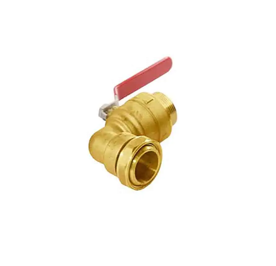
Our ANSI Check Valve, Ball Valve Handle Direction is novel in design with exquisite craftsmanship and strictly controlled to bring a high quality experience to our customers. We"re well-known as one of the leading Boiler Pressure Relief Valve Leaking manufacturers and suppliers in China for our quality products and good service. Please feel free to buy Boiler Pressure Relief Valve Leaking made in China here from our factory.
The water heater is known for its high heat and high pressure. The water heater temperature-pressure relief valve (TPR Valve), protects us from this high heat and pressure. So what is the TPR valve, why does it leak, and what should you do about it?
The TPR valve, also called, a pressure relief valve is a specialized valve at your water heater. This valve is typically on the top or side of your water heater.
The valve functions by releasing water if your water heater becomes too pressurized. Since heated water expands, the water heater can become a ticking time bomb if we were to continually build pressure in your water heater.
As seen in the featured image, a TPR valve is required to have a discharge pipe/tube. This tube should be aimed straight to the ground and never go up. This is because hot water will come out of the TPR valve as it releases water. Therefore, extremely hot water should discharge to the ground for safety.
Additionally, if a pipe were to go up, water will have to work against gravity to empty. So, it is possible a slow drip of the TPR valve will collect water in the tubing and ultimately rust out the valve rather than empty it to the floor.
Be one nominal size larger than the size of the relief valve outlet, where the relief valve discharge piping is installed with insert fittings. The outlet end of such tubing shall be fastened in place.
However, if you find the relief valve to continue to leak even after replacement, you should contact a plumber for assistance. A licensed plumber will be able to evaluate your system and decide on installing an expansion tank or other solutions.
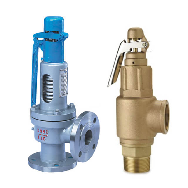
Safety valve is a special valve that the opening and closing parts are normally closed under the action of external force. When the medium pressure in the equipment or pipeline increases beyond the specified value, the medium pressure in the pipeline or equipment is prevented from exceeding the specified value by discharging the medium outside the system. Safety valve belongs to automatic valve category, which is mainly used in boiler, pressure vessel and pipeline. The control pressure does not exceed the specified value, which plays an important role in protecting personal safety and equipment operation. Note the safety valve can only be used after pressure test.
In most cases, the safety valve is the last safety defense line. If the above safety measures fail, the safety valve will take off and release pressure to prevent the pressure in the pressure equipment from exceeding the design allowable value. Safety valve is a kind of intrinsic safety protection measure. It takes off automatically by spring force and medium force, without any manual participation and external force participation, so as to prevent the safety accident caused by human misoperation. The function of the safety valve is realized through the following action process: when the system reaches the maximum allowable pressure, the safety valve can be opened accurately, and can discharge stably with the increase of the system pressure, and can discharge the rated amount of working medium under the rated discharge pressure. When the system pressure drops to a certain value, it should be closed in time, and keep the necessary sealing under the closed state Sex.
According to the different overall structure and loading mechanism, the common types of safety valve are spring loaded safety valve, balance bellows safety valve and pilot safety valve.
Spring loaded safety valve is a common safety valve, which overcomes the force produced by the medium pressure under the valve disc by the closing force of the spring. If the medium is harmless to people and the environment, such as non-toxic, non flammable and low-cost, such as air, it can be directly discharged into the atmosphere, in this case, the ordinary safety valve is used.
Balanced bellow safety valve, the effective area of the bellow is equal to the area of the sealing surface of the valve seat, which is used to counteract the effect of back pressure on the set pressure. It is suitable for the working conditions of high temperature and pressure, high back pressure or the medium can not be directly discharged into the atmosphere.
The pilot type safety valve is usually composed of a main valve with a movable unbalanced disc and an external pilot valve (piston). It drives or controls the opening and closing of the main valve by means of the medium discharged from the pilot valve. Compared with the balanced bellows type safety valve, its back pressure compensation coefficient is higher, which reduces the influence of back pressure on the action characteristics to a minimum and the discharge volume is large. For example, in the process of overpressure, the discharge of medium in the reactor is very large. If the balance bellows type safety valve is used, 16 sets are needed at most. If the pilot type safety valve is selected, 8 sets are enough, or even less. It will bring many advantages to users, such as less installation, less maintenance, less work and convenient maintenance. Of course, the technical complexity of the pilot safety valve is high, which puts forward higher requirements for the technical level of operators.
In the load spring safety valve, the valve closing pressure or spring force is applied by the coil spring under the pressure of the adjusting screw. The spring force is transferred to the disc through the stem. As long as the spring force is greater than the force generated at the inlet of the safety valve, the valve disc will seal the nozzle. The following figure shows the expanded nozzle and disc area of the relief valve at the pressure acting on the disc.
According to the preset conditions, the safety valve will open at the preset pressure. The spring force FS is applied in the closing direction, and the force FP generated by the pressure at the inlet of the safety valve is applied in the opening direction. When the pressure FS and medium force FP reach a balance, there is no force to place the valve disc on the valve seat; at this time, the safety valve will start to leak, and the sound of medium discharge can be seen or heard (the sound of medium just discharged).
Before the safety valve is obviously opened, the pressure at the valve inlet must be increased above the set pressure. Due to the flow restriction between the disc and the adjusting ring, the pressure gradually increases in this so-called mixing chamber. This pressure now acts on the expanded disc area, further increasing the pressure FP, which overcomes the additional force required to enter a compression spring. The valve will open quickly with a “bang” and in most cases it will be fully open. Overpressure refers to the pressure increase beyond the necessary set pressure of the safety valve to achieve full opening and full displacement of the valve. This overpressure is usually expressed as a percentage of the set pressure. The value is usually 10%, between 3% and 21% according to relevant specifications and applications.
In most applications, the proper size of safety valve will reduce the pressure when the vessel is discharged. The pressure of the vessel will drop at any subsequent point in time, but not later than the end of the pre-set condition. A decrease in pressure in the vessel will reduce the pressure FP. However, at set pressure, flow still acts on the expanded disc area, which opens the valve. Further pressure reduction is required before the spring force FS exceeds FP again and the relief valve begins to close again. Moreover, under the so-called reseating pressure, the disc will contact the nozzle again and the safety valve will close again. Return pressure difference refers to the difference between the set pressure of the safety valve and the return pressure, which is calculated as a percentage of the set pressure. According to the definition of relevant codes and standards, the reseating differential pressure is generally – 7% to – 10%, and it is – 4% to – 20% according to relevant codes and services (steam, gas or liquid).
API 526 safety valve series has a down regulating ring, and its set pressure is defined as the set pressure of the valve when the pressure reaches the initial discharge sound.
It is important to understand that the operating pressure of the protected equipment should be less than the reseating pressure of the safety valve. Most manufacturers and relevant codes and standards recommend that the difference between the reseating pressure and the operating pressure of 3% – 5% can achieve reasonable adjustment of the valve seat, and can again achieve good tightness of the valve seat.
Because the area of the pressure chamber is larger than the area of the main valve seat, the closing pressure is larger than the opening pressure. This allows the main valve to close tightly.
When the pressure reaches the set pressure, the pilot relief valve is activated. The medium will no longer lead to the pressure chamber (see Figure). This prevents further pressure rise in the pressure chamber.
At the same time, the pressure of the pressure chamber is discharged. Results the closing pressure of the main valve disappeared, which provided the precondition for the system overpressure to push the main valve to open.
The main valve is open. According to the design of pilot safety valve, there are two opening modes of safety valve, one is quick and thorough (quick opening action), the other is gradual and local (regulating action).
When the pressure in the pressure chamber increases, the main valve can be closed again through quick and thorough (quick opening action) or gradual local (regulating action).
Safety valve, also known as overflow valve, is a special valve that the opening and closing parts are normally closed under the action of external force. When the medium pressure in the equipment or pipeline increases beyond the specified value, the medium pressure in the pipeline or equipment is prevented from exceeding the specified value by discharging the medium outside the system. Safety valve belongs to automatic valve category, which is mainly used in boiler, pressure vessel and pipeline. The control pressure does not exceed the specified value, which plays an important role in protecting personal safety and equipment operation. Note the safety valve can only be used after pressure test.
The figure shows several typical structures of the safety valve. Fig. A is a piston type safety valve with a flat valve core. The air source pressure acts on piston A. when the pressure exceeds the safety value determined by the spring force, piston a is jacked open and part of the compressed air is discharged into the atmosphere from the valve port; when the air source pressure is lower than the safety value, the spring drives the piston to move down and close the valve port.
Figure B and figure C are ball valve type and diaphragm type safety valves respectively, with the same working principle as piston type. These three kinds of safety valves are all spring-loaded to provide control force. Adjusting the spring preload can change the safety value, so they are called direct acting safety valves.
Fig. D is a pilot type safety valve. The small direct acting valve provides control pressure to act on the diaphragm. The hard core on the diaphragm is the valve core, which is pressed on the valve seat. When the air source pressure a is greater than the safety pressure, the valve core is opened, and the compressed air is discharged into the atmosphere from the left output hole. The pressure characteristics of the diaphragm safety valve and the pilot safety valve are good and the action is sensitive, but the maximum opening force is relatively small, that is, the flow characteristics are poor. In practical application, the type of safety valve should be selected according to the actual needs, and its diameter should be selected according to the maximum exhaust volume.
① before leaving the factory, the opening pressure of the safety valve shall be adjusted one by one to the setting value required by the user. If the user puts forward the working pressure level of the spring, it shall be adjusted according to the lower limit value of the pressure level.
② before installing the safety valve on the protected equipment or before installation, the user must readjust it on the installation site to ensure that the set pressure value of the safety valve meets the requirements.
④ before rotating the adjusting screw, the inlet pressure of the valve shall be reduced below 90% of the opening pressure to prevent the valve disc from being driven to rotate when rotating the adjusting screw, so as to damage the sealing surface.
⑤ in order to ensure the accuracy of the opening pressure value, the medium conditions during adjustment, such as medium type and temperature, shall be close to the actual operation conditions as much as possible. With the change of medium type, especially when the accumulation state of medium is different (for example, from liquid phase to gas phase), the opening pressure often changes. When the working temperature increases, the opening pressure generally decreases. Therefore, when it is adjusted at room temperature and used at high temperature, the set pressure at room temperature shall be slightly higher than the required opening pressure. The degree to which it is related to the valve structure and material selection shall be based on the manufacturer’s instructions.
⑥ when the conventional safety valve is used to fix additional back pressure, the setting value should be less than the required back pressure when the opening pressure is adjusted after testing.
① to adjust the discharge pressure and reseating pressure of the valve, the action test of the valve reaching the full opening height must be carried out. Therefore, it can only be carried out on the large capacity test device or after the safety valve is installed on the protected equipment. The adjustment method depends on the valve structure.
② for the structure with recoil plate and valve seat adjusting ring, the valve seat adjusting ring is used for adjustment. Screw out the fixing screw of the adjusting ring, extend a thin iron bar or other tools from the exposed screw hole, and then move the teeth on the adjusting ring to make the adjusting ring rotate left and right. When the adjusting ring rotates counterclockwise to the left, its position increases, and the discharge pressure and the reseating pressure decrease. On the contrary, when the adjusting ring is rotated clockwise, its position will decrease, and the discharge pressure and reseating pressure will increase. For each adjustment, the adjustment: the rotation range of the ring should not be too large (generally, the number of teeth can be turned). After each adjustment, screw on the fixing screw so that its end is located in the groove between the two teeth of the adjusting ring, which can not only prevent the adjusting ring from turning, but also do not generate radial pressure on the adjusting ring. For the sake of safety, the inlet pressure of the safety valve shall be properly reduced (generally lower than 90% of the opening pressure) before the adjusting ring is moved to prevent the valve from suddenly opening during the adjustment, causing accidents.
③ for the structure with up and down regulating rings (one regulating ring on the guide sleeve and one regulating ring on the valve seat), the adjustment is more complicated. The valve seat adjusting ring is used to change the size of the channel between the disc and the adjusting ring, so as to change the accumulation of pressure in the chamber between the disc and the adjusting ring when the valve is initially opened. When the valve seat adjusting ring is raised, the degree of pressure accumulation increases, so that the valve proportional opening stage is reduced and the sudden rapid opening is achieved quickly. Therefore, raising the valve seat adjusting ring can reduce the discharge pressure. It should be noted that the seat adjusting ring can not be raised too close to the disc. In this way, the leakage at the sealing surface may cause the valve to open prematurely and suddenly, but because the medium pressure at this time is not enough to keep the valve disc in the open position, the valve disc will close immediately, so the valve will jump frequently. Valve seat adjustment: the ring is mainly used to reduce the valve proportion, the opening stage and adjust the discharge pressure, but also has an impact on the reseating pressure.
The upper pitch ring is used to change the angle of the flow medium after reflection at the lower side of the valve disc, so as to change the magnitude of the fluid force, so as to adjust the reseating pressure. When the upper pitch ring is raised, the turning angle decreases, and the fluid force decreases accordingly, so that the reseating pressure increases. On the contrary, when the upper adjusting ring is lowered, the reseating pressure is reduced. Of course, when the upper regulating ring changes the reseating pressure, it also affects the discharge pressure. That is to say, raising the upper regulating ring will increase the discharge pressure, and lowering the upper regulating ring will reduce the discharge pressure, but the effect is not as obvious as the reseating pressure.
After the adjustment of the safety valve, it shall be sealed with lead to prevent any change of the adjusted condition. When repairing the safety valve, the position of adjusting screw and adjusting ring shall be recorded before disassembling the valve, so as to facilitate the adjustment after finishing. Lead sealing shall be applied again after readjustment.
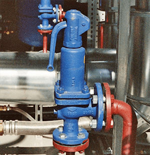
Safety valve is widely used in: steam boiler, liquefied petroleum gas tank car or liquefied petroleum gas railway tank car, oil production well, high pressure bypass of steam power generation equipment, pressure pipeline, pressure vessel, etc.
The safety valve is suitable for clean, particle free, low viscosity fluid. Where it is necessary to install a safety relief device but not suitable for installing a safety valve, a bursting disc shall be installed or the safety valve shall be used in series with the bursting disc.
1. Independent pressure system (with shut-off valve separated from other systems). The system refers to all gas phase, all liquid phase or gas phase connection;
After discharge, the valve disc does not return to its seat: This is mainly caused by the bent stem of spring, incorrect installation position of valve disc or being stuck. It should be reassembled.
Leakage: under the normal working pressure of the equipment, leakage between the valve disc and the sealing surface of the valve seat exceeds the allowable level. The reason is: there is dirt between the valve disc and the sealing surface of the valve seat. The lifting wrench can be used to open the valve several times to wash away the dirt; the sealing surface is damaged. According to the degree of damage, it shall be repaired by grinding or grinding after turning; the valve rod shall be bent, tilted or the lever and fulcrum shall be skewed to make the valve core and disc misplaced. It shall be reassembled or replaced; the spring elasticity shall be reduced or lost. The spring shall be replaced and the opening pressure shall be readjusted.
The safety valve does not open when it reaches the specified pressure: the reason for this situation is the inaccurate constant pressure. The compression amount of the spring or the position of the heavy hammer shall be readjusted; the disc and the valve seat shall be stuck. The safety valve shall be subject to manual air release or water discharge test regularly; the lever of the lever type safety valve is stuck or the heavy hammer is moved. The position of the hammer should be readjusted and the lever should move freely. [span]
The pressure continues to rise after exhaust: This is mainly because the displacement of the selected safety valve is less than the safe discharge capacity of the equipment, so the appropriate safety valve should be re selected; the valve rod center line is not correct or the spring is rusted, so that the valve disc cannot be opened to the proper height, so the valve rod should be re assembled or the spring should be replaced; if the section of the exhaust pipe is not enough, the exhaust pipe conforming to the safe discharge area should be adopted.
Safety valve disc frequency jump or vibration: mainly due to the spring stiffness is too large. The spring with proper rigidity should be used; the adjustment ring is not adjusted properly, so that the reseating pressure is too high. The position of the adjusting ring should be readjusted; the resistance of the discharge pipe is too large, resulting in excessive discharge back pressure. The discharge pipe resistance shall be reduced.
The safety valve is opened when the specified pressure is not reached: the main reason is that the constant pressure is not correct; the aging spring force decreases. The adjusting screw shall be tightened properly or the spring shall be replaced.
According to the diversity and complexity of coal chemical system pressure and medium, the influence of temperature, pressure, medium and other factors in the equipment shall be considered when selecting the safety valve, and the appropriate safety valve model shall be configured according to the flow diameter and diameter of the safety valve according to the design requirements. When determining the safety valve, its nominal pressure must be greater than the set pressure. When the valve reaches full opening, the pressure cannot exceed the nominal pressure of the safety valve. The smaller the working pressure range of the spring is, the better the working performance of the safety valve will be.
(1) If the non-toxic and pollution-free medium is allowed to leak to the atmosphere, open full open safety valve with valve cap shall be selected; if regular opening test is required for safety valve, safety valve with lifting wrench shall be selected. When the medium pressure reaches more than 75% of the set pressure, lifting wrench shall be used to check the flexibility of valve opening.
(2) Closed safety valve must be used for toxic or flammable medium, and good sealing shall be provided at the valve cover and protective cover gasket to ensure that the discharged medium does not leak out. After the safety valve takes off, the medium shall be discharged according to the specified outlet, and air tightness test shall be conducted at the same time.
(3) In the case of high back pressure, the back pressure balanced safety valve or pilot safety valve shall be selected. If necessary, two safety valves for mutual standby shall be installed. The mechanical interlock device shall be used for the inlet and outlet shut-off valve to meet the medium discharge required by the equipment during maintenance.
(4) The bellows safety valve shall be selected for the medium with high toxicity, strong corrosion and extreme danger. The bellows safety valve uses bellows to isolate the spring and guide mechanism from the medium, eliminate the impact of back pressure fluctuation on the valve performance, and protect the spring and other internal parts from medium corrosion.
① when the operating temperature of the closed safety valve exceeds 250 ℃ and the operating temperature of the open safety valve exceeds 350 ℃, the safety valve with radiator shall be selected;
② when the gas medium pressure in the equipment is greater than 3.0 MP, and when the temperature exceeds 235 ℃, the safety valve with radiator shall be used.
Safety valve is an important accessory of pressure limiting and pressure relief for special equipment (boiler, pressure vessel, pressure pipeline, etc.). Therefore, pay attention to the following points when setting the safety valve:
(2) when the safety valve is used for discharging flammable liquid, the outlet of the safety valve shall be connected with the emergency storage tank. When the discharged material is high temperature combustible, the receiving container shall be equipped with corresponding protective facilities.
(3) the general safety valve can be vented locally, and the vent port shall be more than 1 meter (m) higher than the operator, and shall not face the open fire location, spark emission location and high-temperature equipment within 15 meters (m). The vent of safety valve of indoor equipment and container shall lead out from the roof and be more than 2m (m) higher than the roof.
(4) when there is a block valve at the inlet of the safety valve, the block valve shall be in the normally open state and shall be lead sealed to avoid mistakes.
(1) the cross-sectional area of the through-hole of the connecting pipe and pipe fitting between the safety valve and the boiler or pressure vessel shall not be less than the inlet cross-sectional area of the safety valve; if several safety valves share one inlet pipe, the flow cross-sectional area of the inlet pipe shall not be less than the sum of the inlet cross-sectional area of the safety valve.
(2) generally, stop valve shall not be installed between safety valve and boiler drum or header, or take out pipe of steam. It is generally not suitable to install stop valve or other outlet pipe between safety valve and pressure vessel; for pressure vessel containing highly toxic, highly and moderately hazardous, inflammable, corrosive, viscous medium or precious medium, stop valve can be installed between safety valve and pressure vessel only with the approval of the technical director in charge of pressure vessel of the user and the formulation of reliable preventive measures 。 During normal operation of the pressure vessel, the stop valve must be kept fully open, sealed or locked with lead. The structure and diameter of the stop valve shall not hinder the safety relief of the safety valve.
(3) the spring-loaded safety valve with threaded connection shall be connected with the short pipe with thread, and the short pipe shall be welded with the simplified body and header.
(4) the safety valve must be equipped with discharge pipe. The drain pipe shall avoid twists and turns as much as possible to minimize resistance. The discharge pipe shall be directly connected to a safe place and have sufficient circulation cross-sectional area to ensure smooth exhaust. For the safety valve that can interact with each other to produce chemical reaction, it is not allowed to share a discharge pipe; when the safety valve is installed on the equipment with corrosive and combustible gas, anti-corrosion or anti fire and explosion measures shall also be taken during discharge; when the equipment with safety valve is toxic medium, and the vapor density of the medium is greater than the air density, the medium and steam discharged from the safety valve shall be introduced to Closed system, and recovered from closed system to use in production.
(6) the safety valve installed in the open air shall be provided with reliable measures to prevent the discharge of the safety valve from being affected by the freezing of the water contained in the valve medium when the temperature is lower than 0oC.
(7) when the medium crystallization temperature of the safety valve is higher than the minimum ambient temperature, the safety valve must be equipped with insulation jacket, and installed with insulation purging steam to prevent the medium crystallization from blocking the safety valve and affecting the normal operation performance of the safety valve. The inlet and outlet pipes of the safety valve must also be designed with steam insulation jacketed pipe or added with insulation steam tracing pipe to prevent medium crystallization from blocking the pipe.
Due to different production requirements, equipment properties and process requirements, safety valve standards adopted are also different. Common international standards include ASME, API, ISO, JIS, DIN, BS, ghost, etc. common domestic standards include GB, JB and TSG There are some differences in the regulations of safety valve in each standard.
When marking the working temperature andWorking pressureWhen working pressure must be marked with P and attached to the lower right corner of the P word.mediumThe maximum temperature is the integer obtained from the maximum temperature of 10 except the medium. For example, the working temperature is 540 C and the working pressure is 10MPa.valveIts code name is P54100.
1. The safety valve shall be equipped with a device to prevent the hammer from moving by itself and a guide frame to limit the lever from deviating. The spring safety valve shall be equipped with a device to lift the handle and prevent the adjustment screw from being unscrewed at will.
2. It shall be installed vertically at the highest position of the boiler manufacturer and header. Between the safety valve and the drum or header, there shall be no outlet pipe and valve for taking steam.
3. The cross-sectional area of the connecting pipe between the safety valve and the boiler shall not be less than the cross-sectional area of the inlet of the safety valve. If several safety valves are installed together on a short pipe directly connected to the drum, the passage cross-sectional area of the short pipe shall not be less than 1.25 times of the exhaust area of all safety valves.
4. For the boiler with rated steam pressure less than or equal to 3.82MPa, the safety valve throat diameter shall not be less than 25mm; for the boiler with rated steam pressure greater than 3.82MPa, the safety valve throat diameter shall not be less than 20mm.
5. Generally, the safety valve shall be equipped with exhaust pipe, which shall be directly connected to the safety place and have sufficient cross-sectional area to ensure smooth exhaust. The bottom of the vent pipe of the safety valve shall be equipped with a drain pipe connected to the safety place. It is not allowed to install a valve on the vent pipe and drain pipe.
6. The safety valve of pressure vessel should be directly installed on the highest position of pressure vessel. The safety valve of liquefied gas storage tank must be installed at the gas phase position. Generally, short pipe can be used to connect with the vessel, so the diameter of the short pipe of the safety valve shall not be less than the valve diameter of the safety valve.
7. Generally, no valve shall be installed between the safety valve and the container. For the container with inflammable, explosive or viscous medium, in order to facilitate the cleaning or replacement of the safety valve, a stop valve can be installed. The stop valve must be fully opened and lead sealed during normal operation to avoid disorderly movement.
8. For boilers with rated evaporation capacity greater than 0.5t/h, at least two safety valves shall be installed; for boilers with rated evaporation capacity less than or equal to 0.5t/h, at least one safety valve shall be installed. Safety valves must be installed at the outlet of separable economizer and steam superheater.
9. For the pressure vessel with inflammable, explosive or toxic medium, the medium discharged by the safety valve must have safety device and recovery system. The installation of the lever type safety valve must be kept in a vertical position, and the spring safety valve should also be installed vertically to avoid affecting its action. During installation, attention shall also be paid to fit, coaxiality of parts and uniform stress of each bolt.
10. The outlet of the safety valve shall be free of resistance to avoid back pressure. If a discharge pipe is installed, its inner diameter shall be larger than the outlet diameter of the safety valve. The discharge port of the safety valve shall pay attention to antifreeze. For containers containing inflammable, toxic and highly toxic media, the discharge pipe shall be directly connected to the outdoor safe place or have facilities for proper treatment. No valve is allowed to be installed in the discharge pipe.
11. The newly installed safety valve shall be attached with the product certificate. Before installation, it shall be recalibrated, lead sealed and safety valve calibration shall be issued.
12. No valve shall be installed between pressure equipment and safety valve. For containers containing inflammable, explosive, toxic or viscous media, in order to facilitate replacement and cleaning, stop valve can be installed. Its structure and size shall not hinder the normal operation of safety valve. In normal operation, the stop valve must be fully opened and sealed with lead.
When the operation of coal chemical system is not stable, the medium in the equipment is affected by the change of system pressure and temperature, the particles and impurities in the medium will rush into the valve body, and some solid impurities fall on the sealing surface, causing the gap between the valve core and the valve seat to cause leakage, forming pressure marks on the sealing surface, and forming pits and grooves caused by the corrosion of the medium between the sealing surfaces, resulting in the continuous leakage of the medium Or adhesion can not meet the production requirements, then the safety valve should be repaired.
The repair of safety valve is mainly the repair of the sealing surface of safety valve. Most of the safety valves on the chemical equipment are left with pungent chemicals after use. Attention shall be paid to the protection during disassembly. The valve body and spring of some safety valves are adhered with solidification medium. After disassembly, high temperature steam or other non corrosive cleaning agent shall be used to remove residues. The sealing surface of non-metallic material is generally replaced or turned after being damaged. The metal sealing surface is grinded when the damage is not serious. When lapping, the valve seat and the valve core must be separately lapping with a flat grinding tool. When the sealing surface is seriously damaged or has obvious pressing damage and other defects, use abrasive paste with particle size of 300-400 for initial grinding, then use abrasive paste with particle size of 600-800 for fine grinding, and finally use abrasive paste with particle size of 1000-1200 for polishing and fine grinding. Each time when changing the abrasive paste, it must be cleaned with acetone. When polishing and fine grinding, apply a small amount of abrasive paste to grind gently until it is bright. After grinding, put the valve core And the grinding paste on the sealing surface shall be cleaned up, and after several times of grinding, the sealing requirements shall be met.
Online calibration and calibration bench calibration are the two most commonly used calibration methods, and appropriate calibration methods are selected according to the operating conditions of equipment, medium type, operating pressure and other factors in coal chemical plant. The advantage of on-line calibration is that it is carried out when the equipment is running, the safety valve does not need to be disassembled from the equipment, and the calibration speed is fast, which is convenient for the calibration of welded safety valve. At the same time, the reseating pressure can be measured, and the calibration result is closer to the actual working condition; the disadvantage is that the calibration is dangerous, so the tightness test cannot be carried out. The calibration of the calibration bench is to open the safety valve through nitrogen, water and other media and record the opening pressure. The advantage is to solve the setting and leakage detection of the safety valve with normal temperature medium and working temperature below 250 ℃, save the adjustment time of the newly installed safety valve, reduce the energy consumption and reduce the work risk. The disadvantage is that there is an error between the operating temperature and the normal temperature (the spring becomes soft under high temperature), so it can only be opened The setting of starting pressure and sealing test can not verify the reseating pressure. During the calibration, it should be noted that the calibration bench should be used for the safety valve that cannot consider back pressure safety valve, high temperature or low temperature medium. The adjustment of calibration spring of high pressure safety valve can only be fine adjusted, and the air flow and water flow for calibration must be filtered.
During the calibration of safety valve, attention shall be paid to the adjustment of reseating pressure, which refers to the static pressure at the inlet of safety valve when the valve disc contacts the valve seat again with the decrease of system pressure, the valve opening height is zero, and the medium stops flowing out continuously. If the reseating pressure is too low and the medium outflow is large, the loss of medium and energy will be caused. If it is too high to discharge the system medium, the valve will have frequency jump. Therefore, in the case of rich experience, the reseating pressure will be adjusted as high as possible to reduce the loss of medium and energy. The adjustment method is to adjust the clearance through the adjusting ring. The smaller the clearance is, the greater the resistance when ejecting, the greater the force to hold the valve core to drop, the more difficult it is to reseat; the larger the clearance is, the easier it is to fall back, and the higher the reseating pressure is. Since the normal temperature calibration bench is unable to carry out the opening height and emission test, the regulating ring shall be kept in the factory state when the calibration bench is used to calibrate the safety valve.

D&R Metal Industry is China’s no.1 manufacturer and source of high-quality brass pressure relief valves. We have served thousands of plumbing industries and clients internationally. We maintain our good reputation by satisfying customers’ needs and exceeding their expectations.
Since its establishment, D&R Metal Industry is serving customers with the best quality brass pressure relief valves. We manufacture products using our advanced equipment and state-of-the-art production facilities.
Our complete set of forging machines and CNC machines assure you full capabilities in providing your brass pressure relief valve needs. D&R Metal Industry has been continuously improving the quality of products to ensure enhanced and up-to-date features.
Through constant innovation, D&R Metal Industry can provide you the best design and superior quality of brass pressure relief valves. We always make sure to produce products that will meet your requirements. Thus, we offer custom services according to your exact specifications.
As the best manufacturer in China, we only used superior quality raw materials for your brass pressure relief valves. Our engineers carefully selected solid and 100% tested brass materials. With its excellent properties, you can assure high-quality.
We manufacture brass pressure relief valves that are widely used for limiting or controlling surges of pressure in a pipeline. It can protect your system against equipment or instrument failure. D&R Metal Industry manufactures different types of brass pressure relief valves such as spring-loaded relief valves.
Other than that, we designed brass pressure relief with different pressure ratings based on applications. It also comes in unlimited sizes and designs. With their compact structure and design, D&R brass pressure relief valves will meet various space requirements.
D&R Metal Industry always makes sure that your brass pressure relief valves are tested rigorously to ensure higher quality. We also thoroughly inspected your products before shipment for their safety during delivery.
If you have inquiries or questions about our brass pressure relief valves, message us immediately. We have 24/7 assistance to support you. Our highly knowledgeable sales team will always accommodate your needs.
Water Pressure Relief ValvesWater Pressure Relief Valves: Water pressure relief valves, alternatively referred to as water pressure-lowering valves, are frequently employed by private and municipal water delivery organizations.
Available in various lengths, widths, and pipe sizes to fit different machines.Hydronic Pressure Valves: Hydronic pressure relief valves are a category of pressure relief valves designed specifically for hydronic applications.
Hydronic pressure valves give relief by assuring that these systems are pressurized to a safe working pressure of roughly 4-5 pounds per square inch gauge.
Consider the following additional characteristics of water hydronic pressure valves:Cast iron, forged brass, and stainless steel are all available in a range of models, sizes, and metals.
Here are a few additional properties of back pressure valves:Available in brass, cast iron, bronze, and other metals, these valves frequently feature many functions.

The following product safety recall was voluntarily conducted by the firm in cooperation with the CPSC. Consumers should stop using the product immediately unless otherwise instructed.
Description: Weil-McClain GV water boiler Models GV-3, GV-4, GV-5 and GV-6 with a serial number/date code range of CP5075477 to CP5221234 and built from April 1, 2005 through October 31, 2005. Serial numbers and date codes are located on the left side of the jacket, above the boiler rating label.
As a valve with important protection function, safety valve is widely used in various pressure vessels and piping systems, which can be automatically opened when the system reaches the upper limit of the specified pressure bearing value Discharge the excess medium out of the system, and after the discharge can be automatically closed to ensure that the pressure vessel can be safe, reliable pressure allowed to operate within the scope to avoid major safety accidents.
As a safety valve manufacture, COVNA is committed to helping you to select and manufacture the safety valve you need. Consult us for a free valve solution with the best price.
The normal operation of the safety valve is not only related to the normal safe use of pressure vessels such as boilers but also directly related to the safety of people’s lives and properties. Therefore, great attention must be paid to the common failures of the Boiler Safety Valve And eliminate it in a timely manner.
Valve leakage is one of the most common faults of boiler safety valve. It mainly refers to leakage between valve disc and valve seat under normal working pressure.
1.4 The opening pressure of the valve is too close to the normal pressure of the equipment, so that the sealing surface is lower than the pressure. When the valve is subject to vibration or medium pressure fluctuations, more prone to leakage. The opening pressure should be adjusted according to the strength condition of the equipment.
1.5 Loose Spring Reduces setting pressure and causes valve leakage. May Be due to high temperature or corrosion and other reasons, should be taken to change the spring, or even change the valve and other measures. If it is caused by improper regulation, the adjusting screw can be tightened properly.
Cause 1: Low Return pressure will cause a large number of medium to discharge over time, resulting in unnecessary energy loss. The reason is that the spring pulse relief valve on the large amount of steam discharge, this form of impulse relief valve to open, the medium continues to discharge, vibration relief valve body, or impulse relief valve before and after the force due to the main relief valve medium discharge is not enough to continue to increase, so the steam in the pulse tube along the drum gas header continues to flow impulse relief valve action.
On the other hand because of this type of impulse safety valve action impulse safety valve sealing surface. To its reorganization to form a kinetic pressure zone, the spool will be raised, so that the impulse safety valve continues to discharge, the greater the steam discharge, the role of the spool on the safety of the thrust on the larger, the impulse safety valve will be easier to return to the seat.
Solution 1: At this point, the way to eliminate the fault is to close the throttle valve small, so that the flow of the medium out of the impulse relief valve to reduce the pressure in the kinetic energy pressure zone, so that impulse relief valve back to the seat.
Solution 2: The way to eliminate this failure is to carefully check the size of the spool also guide sleeve parts, with the gap is too small, reduce the disc cover directly or disc stop valve cap diameter or increase the disc and guide sleeve radial gap, to increase the circulation area of the part, so that the steam flow is not diverted when the local pressure to form a high kinetic pressure zone.
Solution 3: The elimination of body surface leakage due to poor flatness of the body surface is to disassemble the valve and re-grind the joint surface until it meets quality standards. If the seal fails due to impurity packing, carefully clean the joint surface to avoid impurity falling into the valve assembly.
Solution 1: The method of eliminating this kind of trouble is mainly solved by opening the throttle valve wider and enlarging the throttle hole diameter.
Casuse 2:On the other hand, the friction between the moving parts and the fixing parts of the main safety valve will cause the main safety valve to return to the seat slowly.
The vibration phenomenon of safety valve in the process of discharging is called the chatter of safety valve. The chatter phenomenon easily causes metal fatigue, which reduces the mechanical performance of Safety Valve and causes serious hidden trouble of equipment.
Solution 1: The elimination method is that the rated discharge of the valve should be used as close as possible to the necessary discharge of the equipment.
Cause 2: On the other hand, because the diameter of the inlet pipe is too small, smaller than the inlet diameter of the valve, or the resistance of the inlet pipe is too big.
Solution 2: The method of elimination is when the valve is installed, the internal diameter of the inlet pipe should not be less than the inlet diameter of the valve or the resistance of the inlet pipe should be reduced This can be solved by reducing the resistance of the discharge line.
Boilers operate under extreme pressure and extreme fluctuations in temperature, often undergoing swings in temperature of hundreds of degrees Fahrenheit.
This guide to boiler inspections covers the basics of what a boiler is and does, what happens during a boiler inspection, the work that an inspector of boilers does, and how industries that use boilers can benefit from employing a drone for their inspections.
A boiler is a closed vessel whose purpose is the creation of hot water or steam. This steam is then used as a power source for various purposes (see the next section for some examples).
Typically, in order to create steam in a boiler, coal, oil or gas is converted into heat by combustion. That heat is then applied to the water contained in the boiler and, as the water is heated, it turns into steam.
But boilers don’t simply heat water in order to produce steam. Conditions within a boiler are also optimized to increase the boiling point of water through pressurization. This works the same way in a pressure cooker, where an airtight seal speeds up the time it takes to boil water, or to cook in general.
Through the combination of pressure, an efficient fuel source, and an efficient mechanism for transferring heat to the water, boilers are able to create huge amount of energy in the form of steam.
There are many different types of boilers out there. The difference between them has to do with the way heat is conveyed to or through the water in order to turn it into steam.
Fire-Tube Boiler.In a fire-tube boiler, fuel is burned inside the furnace and then the heat produced is transferred by tubes through the water in the tank to generate steam. Fire-tube boilers are one of the cheapest types of boilers to create since their design and construction is fairly straightforward. For the same reason, they are typically limited to low and medium pressure applications because their shell is not thick enough for higher pressures.
Recovery Boiler. Recovery boilers are used in the pulp and paper industry. They burn black liquor (a pulping byproduct) and recover inorganic elements in order to generate superheated steam.
Water-Tube Boilers. Water-tube boilers are similar to fire-tube boilers, but in water-tube boilers water tubes are heated inside the furnace to create steam instead of heating fire tubes that then transfer heat to the water inside of a tank. Water-tube boilers are more efficient than fire-tube boilers, but also more complex and therefore more expensive.
Biomass Boiler. Biomass boilers are similar to gas-fueled boilers except that they use bio fuel, such as wood chips, wood pellets, logs, or other forms of biomass to create heat instead of using fossil fuels.
But these plates can crack and buckle over time, which is why proper maintenance procedures are so important. If a problem goes undetected for too long, the boiler could suddenly explode with a force equivalent to a bomb going off.
Another concern is preserving the longevity of the boiler. Even if a disaster is not imminent, allowing a flaw to persist without maintenance could lead to a shorter lifespan for the asset, which will lead to increased costs for the company.
Most laws and insurance company guidelines recommend an annual inspection of large boilers. This inspection would be a thorough internal and external inspection, with the boiler cool and under no pressure.
Studies have shown that increasing the frequency of boiler inspections can lead to an increase in the asset life and a reduction in the release of greenhouse gases, but companies have to weigh these benefits against the cost of doing more inspections.
Boiler inspections are done by trained and certified technical specialists who are experts in the inspection of boilers. Given the high degree of specialization required for boiler inspections, companies usually contract out this type of work instead of using someone in-house.
Because boilers can be extremely dangerous if not properly maintained, the processes for inspecting them are rigorous and required by law in most countries.
The American Society of Mechanical Engineers (ASME) has created standards and codes for the installation of boilers, and the American Petroleum Institute (API) has created standards for boiler inspections, both of which are followed all over the world.
One aspect of these requirements is that inspections must be conducted by certified steam boiler inspectors, usually in the presence of a representative from a formal inspection body.
The goal for both the external and the internal inspection is to conduct a visual review of each part of the boiler in order to identify potential problems that could require maintenance.
While external inspections are straightforward and do not require any special preparation beyond making sure the boiler is cool and depressurized, internal boiler inspections can be difficult because of limitations with accessing various parts of a boiler.
In a manual internal boiler inspection, an inspector must physically enter the boiler, which requires the company to build scaffolding for the inspector to stand on during the inspection. Once the inspection is complete, the scaffolding must then be taken down after the inspection.
Boiler room condition. As part of a boiler inspection inspectors will usually inspect the room in which the boiler sits to make sure there is no flammable debris or other encumbrances that could present a safety hazard.
Nameplate. Inspectors will often begin their work at the nameplate, where they can find out the boiler type, when the boiler was made, the maximum pressure allowable in the boiler, and the types of controls needed for the boiler according to ASME manufacturing code and NBIC (National Board Inspection Code) requirements.
Safety valve. From a safety perspective, the safety valve is arguably the most important part of a boiler and will be an important device to review during a boiler inspection. If a problem develops in the boiler, the safety valve (also called the Relief Valve) will help prevent over-pressurization, which can lead to an explosion.
Control safety devices. Also of high importance for safety are control safety devices. Examples include the fuel train, the emergency shut off switch, and operating switch. All of these devices must be visually examined during a typical boiler inspection to ensure continued safe use of the boiler.
Piping. Boiler room piping is used to move water and fuel in and out of the boiler. The condition of the piping must be reviewed during any boiler inspection, both to ensure that it is still in good condition and also to ensure that it is the right kind of piping for the ways it’s being used according to ASME standards. Flue pipe connections must also be inspected to ensure that carbon monoxide is being expelled properly, and not building up in the boiler room.
Fresh air for combustion. Burners within a boiler must receive the correct ratio of fuel to air, which is why inspectors will review the combustion air requirements of the boiler during an inspection to make sure the air pathway is open and providing enough fresh air for the boiler to work properly.
Walls and surfaces. All internal walls and surfaces are inspected, looking for any signs of leaks, corrosion, overheating, or other structural issues within the boiler.
Using a drone instead of a person for collecting visual data in a boiler inspection has several benefits, the biggest of which are safety and savings.
Boilers present many challenges for flying, since the space within them is tight and full of objects for a drone’s blades to hit, which would immediately bring a normal drone crashing down.
Flyability drones are designed specifically for inspections inside confined spaceslike boilers, and help address all of these challenges. Flyability’s
Sending a drone into a confined space instead of an inspector keeps people out of potentially dangerous scenarios, improving the overall safety for those involved in the boiler inspection process.
Using a drone made just for indoor inspections, such as the Elios 3, inspectors can get a close view of burners, tubes, and other parts of the boiler that are typically hard to access during a manual inspection.

Your pressure relief valve is making a strange noise, and you’re worried about potential damages to the surrounding pipes and valves. When you hear moaning noises coming from a valve, or even sounds like sputtering, vibrations, or hissing noises coming from your pressure relief valve, it can be a cause for alarm. You’ll want to find the root cause of your noisy valve as soon as possible, and we’re here to help.
There are many reasons why your pressure relief valve is making noises. In some cases, these noises can be a sign your pressure valve is bad. In order to help you diagnose the problem, let’s divide the causes into the following three categories of valve noises: mechanical vibration noise, fluid dynamics noise, and aerodynamics noise. Now, let’s take a closer look at each of these causes of noises from sanitary pressure relief valves.
Various parts of pressure relief valves produce mechanical vibrations when fluid flows through them. Usually, this vibration is not noticeable, but it can become a nuisance when maintenance is required. These mechanical vibrations can be divided into two types:
Low-frequency vibrations are caused by jets and pulsations in the fluid medium brought on by fast flow rates at the valve outlet, unreasonable or inefficient pipeline layouts, and insufficient stiffness of the active parts of the valve.
High-frequency vibrations create resonance when the natural frequency of the valve coincides with the excitation frequency caused by the fluid flow. This phenomenon occurs within a certain range of pressure-reducing sanitary pressure relief valves. And the changes in noise can be very large once there’s even the slightest change in conditions. This kind of mechanical vibration noise has nothing to do with the flow rate of the medium but is primarily due to the unreasonable design of the pressure relief valve.
Fluid dynamics can generate noise from turbulence and eddy currents after the fluid passes through the valve’s pressure-reducing port. The process can be divided into two stages:
Turbulence noise is generated by the interactions between the turbulent fluid and the pressure relief valve or pipe surface. Its frequency and noise level are relatively low, which generally does not constitute a noise problem. If it does become a noise issue, you may need to rearrange the pipeline more efficiently.
During the valve’s pressure-reducing process, the fluid (liquid) will begin to vaporize once the fluid flow rate reaches a particular value. When the pressure on the bubble inside the liquid reaches a specific level, the bubble will explode, leading to very high pressure and shock waves in some parts. The instant pressure of the impact can be up to 196MPa. The pressure will sharply decline in locations far away from the center of the explosion. Shock waves can be a major factor in cavitation noises coming from the pressure relief valve.
When vapor and other compressible fluid pass through the pressure-reducing portion of the pressure relief valve, the fluid’s mechanical energy is converted into sound energy, and the water regulator produces an audible nuisance.
While these are the most common causes of noisy valves, there are several more possibilities. In rare cases, a failed expansion tank, quick closing pressure relief valves on new appliances, bad vacuum breakers, faulty valves with loose washers, or even improperly strapped pipes can be the cause of those noises coming from your pressure relief valve. In addition to the noises, also check for the signs that your pressure valve is bad.
First, check for a specified replacement cycle on the valve itself. If there is no date listed, you can also check the manufacturer’s website or contact them directly. If you still can’t find the specified replacement life cycle, you should replace most pressure relief valves five years after the manufacture date. Many i


 8613371530291