
boiler safety valve lifting pressure quotation

Boiler explosions have been responsible for widespread damage to companies throughout the years, and that’s why today’s boilers are equipped with safety valves and/or relief valves. Boiler safety valves are designed to prevent excess pressure, which is usually responsible for those devastating explosions. That said, to ensure that boiler safety valves are working properly and providing adequate protection, they must meet regulatory specifications and require ongoing maintenance and periodic testing. Without these precautions, malfunctioning safety valves may fail, resulting in potentially disastrous consequences.
Boiler safety valves are activated by upstream pressure. If the pressure exceeds a defined threshold, the valve activates and automatically releases pressure. Typically used for gas or vapor service, boiler safety valves pop fully open once a pressure threshold is reached and remain open until the boiler pressure reaches a pre-defined, safe lower pressure.
Boiler relief valves serve the same purpose – automatically lowering boiler pressure – but they function a bit differently than safety valves. A relief valve doesn’t open fully when pressure exceeds a defined threshold; instead, it opens gradually when the pressure threshold is exceeded and closes gradually until the lower, safe threshold is reached. Boiler relief valves are typically used for liquid service.
There are also devices known as “safety relief valves” which have the characteristics of both types discussed above. Safety relief valves can be used for either liquid or gas or vapor service.
Nameplates must be fastened securely and permanently to the safety valve and remain readable throughout the lifespan of the valve, so durability is key.
The National Board of Boiler and Pressure Vessel Inspectors offers guidance and recommendations on boiler and pressure vessel safety rules and regulations. However, most individual states set forth their own rules and regulations, and while they may be similar across states, it’s important to ensure that your boiler safety valves meet all state and local regulatory requirements.
The National Board published NB-131, Recommended Boiler and Pressure Vessel Safety Legislation, and NB-132, Recommended Administrative Boiler and Pressure Vessel Safety Rules and Regulationsin order to provide guidance and encourage the development of crucial safety laws in jurisdictions that currently have no laws in place for the “proper construction, installation, inspection, operation, maintenance, alterations, and repairs” necessary to protect workers and the public from dangerous boiler and pressure vessel explosions that may occur without these safeguards in place.
The American Society of Mechanical Engineers (ASME) governs the code that establishes guidelines and requirements for safety valves. Note that it’s up to plant personnel to familiarize themselves with the requirements and understand which parts of the code apply to specific parts of the plant’s steam systems.
High steam capacity requirements, physical or economic constraints may make the use of a single safety valve impossible. In these cases, using multiple safety valves on the same system is considered an acceptable practice, provided that proper sizing and installation requirements are met – including an appropriately sized vent pipe that accounts for the total steam venting capacity of all valves when open at the same time.
The lowest rating (MAWP or maximum allowable working pressure) should always be used among all safety devices within a system, including boilers, pressure vessels, and equipment piping systems, to determine the safety valve set pressure.
Avoid isolating safety valves from the system, such as by installing intervening shut-off valves located between the steam component or system and the inlet.
Contact the valve supplier immediately for any safety valve with a broken wire seal, as this indicates that the valve is unsafe for use. Safety valves are sealed and certified in order to prevent tampering that can prevent proper function.
Avoid attaching vent discharge piping directly to a safety valve, which may place unnecessary weight and additional stress on the valve, altering the set pressure.

Years ago, it was not uncommon to read news about tragic boiler explosions, sometimes resulting in mass destruction. Today, boilers are equipped with important safety devises to help protect against these types of catastrophes. Let’s take a look at the most critical of these devices: the safety valve.
The safety valve is one of the most important safety devices in a steam system. Safety valves provide a measure of security for plant operators and equipment from over pressure conditions. The main function of a safety valve is to relieve pressure. It is located on the boiler steam drum, and will automatically open when the pressure of the inlet side of the valve increases past the preset pressure. All boilers are required by ASME code to have at least one safety valve, dependent upon the maximum flow capacity (MFC) of the boiler. The total capacity of the safety valve at the set point must exceed the steam control valve’s MFC if the steam valve were to fail to open. In most cases, two safety valves per boiler are required, and a third may be needed if they do not exceed the MFC.
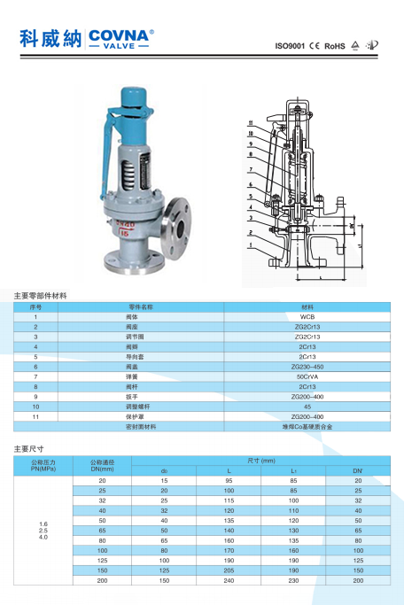
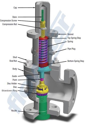
There are three main parts to the safety valve: nozzle, disc, and spring. Pressurized steam enters the valve through the nozzle and is then threaded to the boiler. The disc is the lid to the nozzle, which opens or closes depending on the pressure coming from the boiler. The spring is the pressure controller.
As a boiler starts to over pressure, the nozzle will start to receive a higher pressure coming from the inlet side of the valve, and will start to sound like it is simmering. When the pressure becomes higher than the predetermined pressure of the spring, the disc will start to lift and release the steam, creating a “pop” sound. After it has released and the steam and pressure drops below the set pressure of the valve, the spring will close the disc. Once the safety valve has popped, it is important to check the valve to make sure it is not damaged and is working properly.
A safety valve is usually referred to as the last line of safety defense. Without safety valves, the boiler can exceed it’s maximum allowable working pressure (MAWP) and not only damage equipment, but also injure or kill plant operators that are close by. Many variables can cause a safety valve on a boiler to lift, such as a compressed air or electrical power failure to control instrumentation, or an imbalance of feedwater rate caused by an inadvertently shut or open isolation valve.
Once a safety valve has lifted, it is important to do a complete boiler inspection and confirm that there are no other boiler servicing issues. A safety valve should only do its job once; safety valves should not lift continuously. Lastly, it is important to have the safety valves fully repaired, cleaned and recertified with a National Board valve repair (VR) stamp as required by local code or jurisdiction. Safety valves are a critical component in a steam system, and must be maintained.
All of Nationwide Boiler’s rental boilers include on to two safety valves depending on the size; one set at design pressure and the other set slightly higher than design. By request, we can reset the safeties to a lower pressure if the application requires it. In addition, the valves are thoroughly checked after every rental and before going out to a new customer, and they are replaced and re-certified as needed.
Safety valves are an arrangement or mechanism to release a substance from the concerned system in the event of pressure or temperature exceeding a particular preset limit. The systems in the context may be boilers, steam boilers, pressure vessels or other related systems. As per the mechanical arrangement, this one get fitted into the bigger picture (part of the bigger arrangement) called as PSV or PRV that is pressure safety or pressure relief valves.
This type of safety mechanism was largely implemented to counter the problem of accidental explosion of steam boilers. Initiated in the working of a steam digester, there were many methodologies that were then accommodated during the phase of the industrial revolution. And since then this safety mechanism has come a long way and now accommodates various other aspects.
These aspects like applications, performance criteria, ranges, nation based standards (countries like United States, European Union, Japan, South Korea provide different standards) etc. manage to differentiate or categorize this safety valve segment. So, there can be many different ways in which these safety valves get differentiated but a common range of bifurcation is as follows:
The American Society of Mechanical Engineers (ASME) I tap is a type of safety valve which opens with respect to 3% and 4% of pressure (ASME code for pressure vessel applications) while ASME VIII valve opens at 10% over pressure and closes at 7%. Lift safety valves get further classified as low-lift and full lift. The flow control valves regulate the pressure or flow of a fluid whereas a balanced valve is used to minimize the effects induced by pressure on operating characteristics of the valve in context.
A power operated valve is a type of pressure relief valve is which an external power source is also used to relieve the pressure. A proportional-relief valve gets opened in a relatively stable manner as compared to increasing pressure. There are 2 types of direct-loaded safety valves, first being diaphragms and second: bellows. diaphragms are valves which spring for the protection of effects of the liquid membrane while bellows provide an arrangement where the parts of rotating elements and sources get protected from the effects of the liquid via bellows.
In a master valve, the operation and even the initiation is controlled by the fluid which gets discharged via a pilot valve. Now coming to the bigger picture, the pressure safety valves based segment gets classified as follows:
So all in all, pressure safety valves, pressure relief valves, relief valves, pilot-operated relief valves, low pressure safety valves, vacuum pressure safety valves etc. complete the range of safety measures in boilers and related devices.
Safety valves have different discharge capacities. These capacities are based on the geometrical area of the body seat upstream and downstream of the valve. Flow diameter is the minimum geometrical diameter upstream and downstream of the body seat.
The nominal size designation refers to the inlet orifice diameter. A safety Valve"s theoretical flowing capacity is the mass flow through an orifice with the same cross-sectional area as the valve"s flow area. This capacity does not account for the flow losses caused by the valve. The actual capacity is measured, and the certified flow capacity is the actual flow capacity reduced by 10%.
A safety valve"s discharge capacity is dependent on the set pressure and position in a system. Once the set pressure is calculated, the discharge capacity must be determined. Safety valves may be oversized or undersized depending on the flow throughput and/or the valve"s set pressure.
The actual discharge capacity of a safety valve depends on the type of discharge system used. In liquid service, safety valves are generally automatic and direct-pressure actuated.
A safety valve is used to protect against overpressure in a fluid system. Its design allows for a lift in the disc, indicating that the valve is about to open. When the inlet pressure rises above the set pressure, the guide moves to the open position, and media flows to the outlet via the pilot tube. Once the inlet pressure falls below the set pressure, the main valve closes and prevents overpressure. There are five criteria for selecting a safety valve.
The first and most basic requirement of a safety valve is its ability to safely control the flow of gas. Hence, the valve must be able to control the flow of gas and water. The valve should be able to withstand the high pressures of the system. This is because the gas or steam coming from the boiler will be condensed and fill the pipe. The steam will then wet the safety valve seat.
The other major requirement for safety valves is their ability to prevent pressure buildup. They prevent overpressure conditions by allowing liquid or gas to escape. Safety valves are used in many different applications. Gas and steam lines, for example, can prevent catastrophic damage to the plant. They are also known as safety relief valves. During an emergency, a safety valve will open automatically and discharge gas or liquid pressure from a pressurized system, preventing it from reaching dangerous levels.
The discharge capacity of a safety valve is based on its orifice area, set pressure, and position in the system. A safety valve"s discharge capacity should be calculated based on the maximum flow through its inlet and outlet orifice areas. Its nominal size is often determined by manufacturer specifications.
Its discharge capacity is the maximum flow through the valve that it can relieve, based on the maximum flow through each individual flow path or combined flow path. The discharge pressure of the safety valve should be more than the operating pressure of the system. As a thumb rule, the relief pressure should be 10% above the working pressure of the system.
It is important to choose the discharge capacity of a safety valve based on the inlet and output piping sizes. Ideally, the discharge capacity should be equal to or greater than the maximum output of the system. A safety valve should also be installed vertically and into a clean fitting. While installing a valve, it is important to use a proper wrench for installation. The discharge piping should slope downward to drain any condensate.
The discharge capacity of a safety valve is measured in a few different ways. The first is the test pressure. This gauge pressure is the pressure at which the valve opens, while the second is the pressure at which it re-closes. Both are measured in a test stand under controlled conditions. A safety valve with a test pressure of 10,000 psi is rated at 10,000 psi (as per ASME PTC25.3).
The discharge capacity of a safety valve should be large enough to dissipate a large volume of pressure. A small valve may be adequate for a smaller system, but a larger one could cause an explosion. In a large-scale manufacturing plant, safety valves are critical for the safety of personnel and equipment. Choosing the right valve size for a particular system is essential to its efficiency.
Before you use a safety valve, you need to know its discharge capacity. Here are some steps you need to follow to calculate the discharge capacity of a safety valve.
To check the discharge capacity of a safety valve, the safety valve should be installed in the appropriate location. Its inlet and outlet pipework should be thoroughly cleaned before installation. It is important to avoid excessive use of PTFE tape and to ensure that the installation is solid. The safety valve should not be exposed to vibration or undue stress. When mounting a safety valve, it should be installed vertically and with the test lever at the top. The inlet connection of the safety valve should be attached to the vessel or pipeline with the shortest length of pipe. It must not be interrupted by any isolation valve. The pressure loss at the inlet of a safety valve should not exceed 3% of the set pressure.
The sizing of a safety valve depends on the amount of fluid it is required to control. The rated discharge capacity is a function of the safety valve"s orifice area, set pressure, and position in the system. Using the manufacturer"s specifications for orifice area and nominal size of the valve, the capacity of a safety valve can be determined. The discharge flow can be calculated using the maximum flow through the valve or the combined flows of several paths. When sizing a safety valve, it"s necessary to consider both its theoretical and actual discharge capacity. Ideally, the discharge capacity will be equal to the minimum area.
To determine the correct set pressure for a safety valve, consider the following criteria. It must be less than the MAAP of the system. Set pressure of 5% greater than the MAAP will result in an overpressure of 10%. If the set pressure is higher than the MAAP, the safety valve will not close. The MAAP must never exceed the set pressure. A set pressure that is too high will result in a poor shutoff after discharge. Depending on the type of valve, a backpressure variation of 10% to 15% of the set pressure cannot be handled by a conventional valve.
Shipment: All products and/or services covered by the quotation are sold F.O.B. either our plant in Linden, NJ or the manufacturer"s plant for the parts and/or valves required, unless otherwise indicated. The risk of loss or damage in transit will be upon the purchaser. The products will be prepared for shipment in a manner prescribed by us or the manufacturer and shipped by any public carrier which we deem satisfactory, unless the purchaser provides other specific shipping instructions when placing orders. Any date provided by us for completion of work or for shipment is intended as an estimate only and is not to be deemed a term of the quotation. Shipping charges shall be pre-paid and billed at the time of shipment.
Warranties and Limitations: We warrant only that our products will conform to their description herein and that at the time of sale our products will be free from defects on workmanship and material. The name and reputation of Certified Valve Repair stands prudently behind every valve or piece of equipment we recondition. We are valve repair specialists, if at any time, in any way, a valve or piece of equipment that we have repaired fails to provide complete satisfaction, please bring the matter to our attention. Every repaired valve, pump, instrument, or equipment when used in accordance with the manufacturer and our recommendations is guaranteed to be free from defective workmanship and material. We will repair or replace without charge, F.O.B. our plant any repaired unit which our own examination proves to be defective within a period stated by our firm at the time of delivery. We assume no responsibility for incidental damage or expense. Authorization is required before returned articles will be accepted.

This high capacity steam safety relief valve is built to handle low-pressure steam heating boilers such as hot water heaters or industrial office space boilers. Utilized by residential, commercial and manufacturing, this high capacity safety relief valve is durable and sturdy.

In the latter half of the 19th century explosions of steam boilers were commonplace. As a consequence of this, a company was formed in Manchester with the objective of reducing the number of explosions by subjecting steam boilers to independent examination. This company was, in fact, the beginning of today’s Safety Federation (SAFed), the body whose approval is required for boiler controls and fittings in the UK.
After a comparatively short period, only eight out of the 11 000 boilers examined exploded. This compared to 260 steam boiler explosions in boilers not examined by the scheme. This success led to the Boiler Explosions Act (1882) which included a requirement for a boiler name-plate. An example of a boiler name-plate is shown in Figure 3.7.1.
The serial number and model number uniquely identify the boiler and are used when ordering spares from the manufacturer and in the main boiler log book.
In Europe, matters relating to the suitability of safety valves for steam boilers are governed by the European standard EN 12953. In the US and some other parts of the world, such matters are covered by ASME standards.
The total discharge capacity of the safety valve(s) must be at least equal to the ‘from and at 100°C’ capacity of the boiler. If the ‘from and at’ evaporation is used to size the safety valve, the safety valve capacity will always be higher than the actual maximum evaporative boiler capacity.
The discharge pipework from the safety valve must be unobstructed and drained at the base to prevent the accumulation of condensate. It is good practice to ensure that the discharge pipework is kept as short as possible with the minimum number of bends, so that the allowable backpressure indicated by the valve manufacturer is not exceeded.
It will be quite normal for the internal diameter of the discharge pipework to be more than the internal diameter of the safety valve outlet connection, but under no circumstances should it be less.
A steam boiler must be fitted with a stop valve (also known as a crown valve) which isolates the steam boiler and its pressure from the process or plant. It is generally an angle pattern globe valve of the screw-down variety. Figure 3.7.3 shows a typical stop valve of this type.
In the past, these valves have often been manufactured from cast iron, with steel and bronze being used for higher pressure applications. In the UK, BS 2790 (eventually to be replaced with EN 12953) states that cast iron valves are no longer permitted for this application on steam boilers. Nodular or spheroidal graphite (SG) iron should not be confused with grey cast iron as it has mechanical properties approaching those of steel. For this reason many boilermakers use SG iron valves as standard.
The stop valve is not designed as a throttling valve, and should be fully open or closed. It should always be opened slowly to prevent any sudden rise in downstream pressure and associated waterhammer, and to help restrict the fall in boiler pressure and any possible associated priming.
To comply with UK regulations, the valve should be of the ‘rising handwheel’ type. This allows the boiler operator to easily see the valve position, even from floor level. The valve shown is fitted with an indicator that makes this even easier for the operator.
On multi-boiler applications an additional isolating valve should be fitted, in series with the crown valve. At least one of these valves should be lockable in the closed position. The additional valve is generally a globe valve of the screw-down, non-return type which prevents one boiler pressurising another. Alternatively, it is possible to use a screw-down valve, with a disc check valve sandwiched between the flanges of the crown valve and itself.
The feedwater check valve (as shown in Figures 3.7.4 and 3.7.5) is installed in the boiler feedwater line between the feedpump and boiler. A boiler feed stop valve is fitted at the boiler shell.
The check valve includes a spring equivalent to the head of water in the elevated feedtank when there is no pressure in the boiler. This prevents the boiler being flooded by the static head from the boiler feedtank.
Under normal steaming conditions the check valve operates in a conventional manner to stop return flow from the boiler entering the feedline when the feedpump is not running. When the feedpump is running, its pressure overcomes the spring to feed the boiler as normal.
Because a good seal is required, and the temperatures involved are relatively low (usually less than 100°C) a check valve with a EPDM (Ethylene Propylene) soft seat is generally the best option.
The maintenance of water quality is essential to the safe and efficient operation of a steam boiler. The measurement and control of the various parameters is a complex topic, which is also covered by a number of regulations. It is therefore covered in detail later in this Block. The objective of the next few Sections is simply to identify the fittings to be seen on a boiler.
This controls the amount of Total Dissolved Solids (TDS) in the boiler water, and is sometimes also referred to as ‘continuous blowdown’. The boiler connection is typically DN15 or DN20. The system may be manual or automatic. Whatever system is used, the TDS in a sample of boiler water is compared with a set point; if the TDS level is too high, a quantity of boiler water is released to be replaced by feedwater with a much lower TDS level. This has the effect of diluting the water in the boiler, and reducing the TDS level.
This ejects the sludge or sediment from the bottom of the boiler. The control is a large (usually DN25 to DN50) key operated valve. This valve might normally be opened for a period of about 5 seconds, once per shift.
Figure 3.7.7 illustrates a key operated manual bottom blowdown valve whereas Figure 3.7.8 illustrates an automated bottom blowdown valve and its typical position in a blowdown system.
The dial should be at least 150 mm in diameter and of the Bourdon tube type, it should be marked to indicate the normal working pressure and the maximum permissible working pressure / design pressure.
Pressure gauges are connected to the steam space of the boiler and usually have a ring type siphon tube which fills with condensed steam and protects the dial mechanism from high temperatures.
All steam boilers are fitted with at least one water level indicator, but those with a rating of 100 kW or more should be fitted with two indicators. The indicators are usually referred to as gauge glasses complying with EN 12953.
A gauge glass shows the current level of water in the boiler, regardless of the boiler’s operating conditions. Gauge glasses should be installed so that their lowest reading will show the water level at 50 mm above the point where overheating will occur. They should also be fitted with a protector around them, but this should not hinder visibility of the water level. Figure 3.7.10 shows a typical gauge glass.
Gauge glasses are prone to damage from a number of sources, such as corrosion from the chemicals in boiler water, and erosion during blowdown, particularly at the steam end. Any sign of corrosion or erosion indicates that a new glass is required.
If the water passages are choked an artificially high water level may be observed due to steam condensing in the glass. After testing, the glass will tend to remain empty unless the water level in the boiler is higher than the top connection, in which case water might flow into the glass from this connection.
Gauge glass levels must be treated with the utmost respect, as they are the only visual indicator of water level conditions inside the boiler. Any water level perceived as abnormal must be investigated as soon as it is observed, with immediate action taken to shut down the boiler burner if necessary.
The maintenance of the correct water level in a steam boiler is essential to its safe and efficient operation. The methods of sensing the water level, and the subsequent control of water level is a complex topic that is covered by a number of regulations. The following few Sections will provide a brief overview, and the topic will be discussed in much greater detail later.
The function of the level controls or alarms is checked daily using the sequencing purge valves. With the handwheel turned fully anticlockwise the valve is in the ‘normal working’ position and a back seating shuts off the drain connection. The handwheel dial may look similar to that shown in Figure 3.7.12. Some handwheels have no dial, but rely on a mechanism for correct operation.
Slowly move the handwheel further clockwise to full travel. The water connection is shut-off, the drain valve remains open, and the float chamber and steam connections are blown through. The boiler controls should operate as for lowered water level in boiler i.e. pump running and / or audible alarm sounding and burner cut-out. Alternatively if the level control chamber is fitted with a second or extra low water alarm, the boiler should lock-out.
Sequencing purge valves are provided by a number of different manufacturers. Each may differ in operating procedure. It is essential that the manufacturer’s instructions be followed regarding this operation.
Level control systems with sensors (or probes) which fit inside the boiler shell (or steam drum) are also available. These provide a higher degree of safety than those fitted externally. The level alarm systems may also provide a self-checking function on system integrity.
When a boiler is started from cold, the steam space is full of air. This air has no heat value, and will adversely affect steam plant performance due to its effect of blanketing heat exchange surfaces. The air can also give rise to corrosion in the condensate system, if not removed adequately.
The air may be purged from the steam space using a simple cock; normally this would be left open until a pressure of about 0.5 bar is showing on the pressure gauge. An alternative to the cock is a balanced pressure air vent which not only relieves the boiler operator of the task of manually purging air (and hence ensures that it is actually done), it is also much more accurate and will vent gases which may accumulate in the boiler. Typical air vents are shown in Figure 3.7.14.
When a boiler is taken off-line, the steam in the steam space condenses and leaves a vacuum. This vacuum causes pressure to be exerted on the boiler from the outside, and can result in boiler inspection doors leaking, damage to the boiler flat plates and the danger of overfilling a shutdown boiler. To avoid this, a vacuum breaker (see Figure 3.7.14) is required on the boiler shell.

In order to ensure that the maximum allowable accumulation pressure of any system or apparatus protected by a safety valve is never exceeded, careful consideration of the safety valve’s position in the system has to be made. As there is such a wide range of applications, there is no absolute rule as to where the valve should be positioned and therefore, every application needs to be treated separately.
A common steam application for a safety valve is to protect process equipment supplied from a pressure reducing station. Two possible arrangements are shown in Figure 9.3.3.
The safety valve can be fitted within the pressure reducing station itself, that is, before the downstream stop valve, as in Figure 9.3.3 (a), or further downstream, nearer the apparatus as in Figure 9.3.3 (b). Fitting the safety valve before the downstream stop valve has the following advantages:
• The safety valve can be tested in-line by shutting down the downstream stop valve without the chance of downstream apparatus being over pressurised, should the safety valve fail under test.
• When setting the PRV under no-load conditions, the operation of the safety valve can be observed, as this condition is most likely to cause ‘simmer’. If this should occur, the PRV pressure can be adjusted to below the safety valve reseat pressure.
Indeed, a separate safety valve may have to be fitted on the inlet to each downstream piece of apparatus, when the PRV supplies several such pieces of apparatus.
• If supplying one piece of apparatus, which has a MAWP pressure less than the PRV supply pressure, the apparatus must be fitted with a safety valve, preferably close-coupled to its steam inlet connection.
• If a PRV is supplying more than one apparatus and the MAWP of any item is less than the PRV supply pressure, either the PRV station must be fitted with a safety valve set at the lowest possible MAWP of the connected apparatus, or each item of affected apparatus must be fitted with a safety valve.
• The safety valve must be located so that the pressure cannot accumulate in the apparatus viaanother route, for example, from a separate steam line or a bypass line.
It could be argued that every installation deserves special consideration when it comes to safety, but the following applications and situations are a little unusual and worth considering:
• Fire - Any pressure vessel should be protected from overpressure in the event of fire. Although a safety valve mounted for operational protection may also offer protection under fire conditions,such cases require special consideration, which is beyond the scope of this text.
• Exothermic applications - These must be fitted with a safety valve close-coupled to the apparatus steam inlet or the body direct. No alternative applies.
• Safety valves used as warning devices - Sometimes, safety valves are fitted to systems as warning devices. They are not required to relieve fault loads but to warn of pressures increasing above normal working pressures for operational reasons only. In these instances, safety valves are set at the warning pressure and only need to be of minimum size. If there is any danger of systems fitted with such a safety valve exceeding their maximum allowable working pressure, they must be protected by additional safety valves in the usual way.
In order to illustrate the importance of the positioning of a safety valve, consider an automatic pump trap (see Block 14) used to remove condensate from a heating vessel. The automatic pump trap (APT), incorporates a mechanical type pump, which uses the motive force of steam to pump the condensate through the return system. The position of the safety valve will depend on the MAWP of the APT and its required motive inlet pressure.
This arrangement is suitable if the pump-trap motive pressure is less than 1.6 bar g (safety valve set pressure of 2 bar g less 0.3 bar blowdown and a 0.1 bar shut-off margin). Since the MAWP of both the APT and the vessel are greater than the safety valve set pressure, a single safety valve would provide suitable protection for the system.
However, if the pump-trap motive pressure had to be greater than 1.6 bar g, the APT supply would have to be taken from the high pressure side of the PRV, and reduced to a more appropriate pressure, but still less than the 4.5 bar g MAWP of the APT. The arrangement shown in Figure 9.3.5 would be suitable in this situation.
Here, two separate PRV stations are used each with its own safety valve. If the APT internals failed and steam at 4 bar g passed through the APT and into the vessel, safety valve ‘A’ would relieve this pressure and protect the vessel. Safety valve ‘B’ would not lift as the pressure in the APT is still acceptable and below its set pressure.
It should be noted that safety valve ‘A’ is positioned on the downstream side of the temperature control valve; this is done for both safety and operational reasons:
Operation - There is less chance of safety valve ‘A’ simmering during operation in this position,as the pressure is typically lower after the control valve than before it.
Also, note that if the MAWP of the pump-trap were greater than the pressure upstream of PRV ‘A’, it would be permissible to omit safety valve ‘B’ from the system, but safety valve ‘A’ must be sized to take into account the total fault flow through PRV ‘B’ as well as through PRV ‘A’.
A pharmaceutical factory has twelve jacketed pans on the same production floor, all rated with the same MAWP. Where would the safety valve be positioned?
One solution would be to install a safety valve on the inlet to each pan (Figure 9.3.6). In this instance, each safety valve would have to be sized to pass the entire load, in case the PRV failed open whilst the other eleven pans were shut down.
If additional apparatus with a lower MAWP than the pans (for example, a shell and tube heat exchanger) were to be included in the system, it would be necessary to fit an additional safety valve. This safety valve would be set to an appropriate lower set pressure and sized to pass the fault flow through the temperature control valve (see Figure 9.3.8).
The other advantage of POPRV’s is that whether a snap-acting or modulating pilot is used, the presence of superimposed back pressure does not affect the opening pressure when the valve is in service. This is unlike direct spring safety relief valves, which require expensive and fragile bellows to protect against backpressure.
The modern POPRV can be used confidently in ASME Section VIII applications. POPRV’s provide a leak-free system operation very close to the PRV set pressure. A non-flowing pilot design assures that the POPRV will relief consistently within code tolerances even in “dirty” service applications, thus lower cost of ownership. Since process pressure is used to provide sealing force, a lighter unit weight and smaller size results in a lower cost of installation. POPRV’s provide advanced, reliable, and efficient overpressure protection, utilizing a product technology designed for a wide range of ASME Section VIII applications.
A safety valve is a valve that acts as a fail-safe. An example of safety valve is a pressure relief valve (PRV), which automatically releases a substance from a boiler, pressure vessel, or other system, when the pressure or temperature exceeds preset limits. Pilot-operated relief valves are a specialized type of pressure safety valve. A leak tight, lower cost, single emergency use option would be a rupture disk.
Safety valves were first developed for use on steam boilers during the Industrial Revolution. Early boilers operating without them were prone to explosion unless carefully operated.
Vacuum safety valves (or combined pressure/vacuum safety valves) are used to prevent a tank from collapsing while it is being emptied, or when cold rinse water is used after hot CIP (clean-in-place) or SIP (sterilization-in-place) procedures. When sizing a vacuum safety valve, the calculation method is not defined in any norm, particularly in the hot CIP / cold water scenario, but some manufacturers

Fluidyne BoilerFull Lift Full Flow Safety Relief Valve is a high performance valve designed and developed for steam and water service. It can also be used for most other applications like gases and vapors, saturated steam, superheated steam. Fluidyne Safety Relief Valve is designed for steam service. The valves are designed as per API 520, API 526 and meets the requirements of ASME Sec VIII-Division I. Fluidyne Boiler Safety Valves are offered with IBR Certification in Form III-C. The valves have a full nozzle or half nozzle and guided at the guide of the valve body, increasing the eficiency of the valve assembly. Specially designed disc holder ensures full lift within 5% to 10% overpressure or increase of pressure above the set pressure value. Blow down of a maximum of 5% to 10% is achieved in this design. Lapping of valve seat to optical flatness ensures leak tightness at seat. Full lift of valve disc ensures that the certified flow of the safety valve is discharged. Spring made of chrome vanadium steel is precisely selected and assembled so that the valve operates precisely and a good leak tightness is achieved at high temperatures with great repeatability.


 8613371530291