
boiler safety valve popping test factory

PSV or pressure safety valve is a device to protect the entire system. But to be confident and avoiding of leaving any chance of risk of PSV popping we need to test each and every Pressure safety valve with a specified PSV popping test procedure.
Testing of PSV and its procedure can be different but the findings of each method is to verify the exact working of the Pressure safety valve. In this article we will learn the following:
A pressure relief valve is a safety device that is designed to safeguard pressure-holding equipment during an event of overpressure of the equipment. An overpressure event means a condition that would cause pressure in a vessel that increases beyond the designed pressure or maximum allowable working pressure of that system.
The primary purpose of the pressure relief valve is to protect life and properties from overpressurization of equipment of the system by venting out fluid from overpressurized vessels.
Standard safety valve – A valve in which the opening reaches the degree of lift only necessary to be discharged within a pressure rise of not more than 10% (The valve is characterized by a pop type action and is sometimes known as high lift).
Full lift safety valve – A safety valve that opens rapidly within a 5% pressure rise up to the full lift as limited by the design. The amount of lift up to the rapid opening (proportional range) shall not be more than 20%.
Direct loaded safety valve – A safety valve in which the opening force underneath the valve disc is opposed by a closing force such as a spring or a weight.
Proportional safety valve – A safety valve that opens more or less steadily in relation to the increase in pressure. Sudden opening within a 10% lift range will not occur without a pressure increase. Following opening within a pressure of not more than 10%, these safety valves achieve the lift necessary for the mass flow to be discharged.
Diaphragm safety valve – A directly loaded safety valve in which linear moving and rotating elements and springs are protected against the effects of the fluid by a diaphragm.
Bellows safety valve – A direct loaded safety valve where sliding and (partially or fully) rotating elements and springs are protected against the effects of the fluids by a bellows. The bellows may be of such design that they compensate for the influences of backpressure.
Controlled safety valve– This type of pressure safety valve consists of the main valve and a control device. It also includes direct acting safety valves with supplementary loading in which, until the set pressure is reached, an additional force increases the closing force.
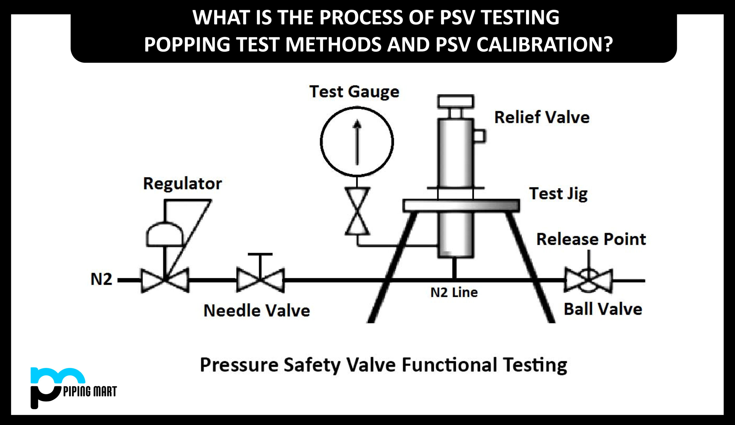
The PSV popping test or Pop test is a set pressure test of pressure safety valves. It is done with the help of compressed air which let flow it in the inlet of PSV until it opens. Then the authorized person for PSV calibration compares the opening force with the set pressure to see whether the valve works well or not.
When the inlet pressure of the pressure safety valve surpasses the threshold pressure, the “popping off” action is produced until the system pressure drops to the designated minimum pressure. The pressure safety valve then resets itself and closes down automatically.
Before testing, Set pressure needs to be determined by the pressure safety valve. A properly manufactured and serviced PSV has a set pressure engraved on the tag which is riveted on the body of the PSV.
Reduce the pressure gradually and record the reseating pressure, i.e. The pressure at which the valve will close. This happens instantly if the pressure source contains too low of a volume, thus making the seating pressure too difficult to record.
Even though the fundamental PRV testing technique is relatively simple, it produces results based on simple observations. Provision of signed certifications allows for little to no traceability other than the technician’s error.
Before putting a PSV into operation each pressure safety valve needs to be tested to protect equipment against overpressure. So it is important that every PSV has to be tested. There are 02 ways of testing of pressure safety valve:
Bench testing is the most popular type of method for testing pressure safety valves because it allows testing PSV in a controlled shop environment. Testing of valves that is already installed in the system requires the system to shut down.
Bench testing of PSV requires removing the pressure-relieving valve from its position and then carrying out a full functional test to check the behavior of the valve in case of overpressurizing.
Correspondingly, PSV testing cost less per testing of the valve in bench testing. But it can result in loss of production if the equipment is shut down or the removal of PSV requires for testing purposes.
When a PSV does not need the removal of the valve from installation or shut down the system is called “Inline or Online PSV testing”. A competent technician can test valves in the system using inline safety relief valve testing equipment to determine the actual setpoint.
In situ, PSV testing proves to be cost-effective as it does not require a plant shut down. But on the other hand, per PSV testing costs are much higher.
When PSV is already installed in the system or attached to the pressure holding equipment, it is costly to test pressure safety valves. In this case, PSVs are tested while in operational conditions. There are two ways of operational testing as follows:
The accumulation testing of PSV is a boiler safety test that determines whether the safety valves can release fluid quick enough to keep the pressure when by more than 10%. The main steam stop valve closes during this testing of the pressure safety valve.
The burner installed on it indicates that the steam pressure will not increase over 10% prior to the safety valve releasing excess steam pressure into the atmosphere.
Hydro testing, also called hydrostatic testing, is performed on pressure vessels to check for leaks. This testing completely fills a pressure vessel with water and pressures it. Once pressurized, leaks can be detected.
Every Pressure safety valve has a set pressure engraved on a plate which is riveted to its body. A set pressure needs to verify before making it functional for any system or pressure holding equipment. Some of the reasons why we need to perform a calibration test of PSV are as follows:
Sometimes, it has been observed that the closed position of the valve is not being activated for a required longer time. This affects the set pressure, so it is a good practice to test the valve.
Overpressure: This is pressure above-set pressure at the point where the valve will open fully. It has a tolerance of up to 10% above the set pressure.
A pressure safety valve or PSV is the last line of defense for all pressure holding systems and equipment that protect it from getting overpressurized. Working of Pressure is completely a mechanical system, hence this needs to be verified before installing it in operations.
It can be hazardous during the calibration or PSV popping test procedure. So, taking care of the operator and testing technician need to be done to make all the processes safe and harmless.
PSV popping test can be done either after installation or before installation. In both cases, the method of testing and its medium can be different to observe the result.
When I teach my steam classes, I ask the attendees, "Do you test the pop safety valve?" Most do not. When I ask why, they tell me the same reason; the safety valve will leak. I joke during the classes that you do not want to test the pop safety valve on a Friday afternoon because it will almost certainly leak. I then ask, Do you check the low water cutoff? They look at me like I have a third eye and say they always check the low water cutoff. If you test the low water cutoff, you should test the pop safety valve. It is the last line of defense against a potential catastrophe. One of the things I do when performing a boiler service call is to explain the duty of the pop safety valve and ask the customer if they would like to have it tested. I explain that it could leak and if they refuse to test it, I will notate it on my service call in case something happens. In this way, my company is protected.
The best way to understand the pop safety valve is to read the instructions which came with the valve. I don"t have a life, and while you are watching the Masked Singer, I read O & M manuals. I know, I"m weird. I figure it"s my job to share things I find while reading these page-turners. The manufacturer hides all sorts of useful tidbits on the installation and maintenance of their valve. I have enclosed some information I gleaned while reading the instructions for a Conbraco/Apollo pop safety valve.
The valve must be mounted in a vertical, upright position directly to a clean, tapped opening in the top of the boiler. I see many safety valves installed horizontally and wonder if that voids the warranty. There should be no restrictions or valves in the piping to or from the safety valve. The installation instructions require the discharge piping to be schedule 40 pipe. They specifically say not to use schedule 80 pipe, which is 50% thicker than schedule 40 pipe. Many installers use copper tubing for the discharge, which does not meet the instructions. The other thing which confuses me the manufacturer instructs you not to use a pipe wrench to install the safety valve. I would wager 99% of all valves are installed using a pipe wrench. I wonder what kind of valve they want you to use.
I consult the pop safety manufacturer or the building insurance company to determine the frequency of tests. Apollo recommends quarterly testing using the Try Lever Test unless the valve is located in a severe service condition, and then it should be done more often. They further state the pop safety valve should have a Pressure Test annually before the heating season or at the end of any non-service period. This test will check your courage as you have to jump out the pressure controls and watch the operation of the boiler as the pressure builds. If the pop safety valve opens at the set pressure, the valve is working properly. This is not a test a novice should do alone.
Apollo suggests checking the pop safety valve at or near the maximum operating pressure by holding the test lever fully open for at least 5 seconds and letting it pop closed. On a low-pressure steam system, the pop safety valve is set for 15 psi. I like to run the boiler steam pressure up to 12 psi or higher to check the pop safety valve. After the test, I drop it to the operating pressure the owner requires. If the valve does not open, the boiler should be shut down until it is checked by a licensed contractor or qualified service person.
The pop safety manufacturer requires a minimum pressure differential of five psi between the pressure relief valve set pressure and the boiler operating pressure. It further states, Under no circumstances should the margin be less than five psig. On a low-pressure steam boiler, the pop safety valve will be set for 15 psi. That means the boiler steam pressure should be ten psi or lower. In breweries, it is common to see the boiler pressure set at 12-14 psi. This is less than the five psi differential and could create a dangerous condition.

Safety is of the utmost importance when dealing with pressure relief valves. The valve is designed to limit system pressure, and it is critical that they remain in working order to prevent an explosion. Explosions have caused far too much damage in companies over the years, and though pressurized tanks and vessels are equipped with pressure relief vales to enhance safety, they can fail and result in disaster.
That’s also why knowing the correct way to test the valves is important. Ongoing maintenance and periodic testing of pressurized tanks and vessels and their pressure relief valves keeps them in working order and keep employees and their work environments safe. Pressure relief valves must be in good condition in order to automatically lower tank and vessel pressure; working valves open slowly when the pressure gets high enough to exceed the pressure threshold and then closes slowly until the unit reaches the low, safe threshold. To ensure the pressure relief valve is in good working condition, employees must follow best practices for testing them including:
If you consider testing pressure relief valves a maintenance task, you’ll be more likely to carry out regular testing and ensure the safety of your organization and the longevity of your
It’s important to note, however, that the American Society of Mechanical Engineers (ASME) and National Board Inspection Code (NBIC), as well as state and local jurisdictions, may set requirements for testing frequency. Companies are responsible for checking with these organizations to become familiar with the testing requirements. Consider the following NBIC recommendations on the frequency for testing relief valves:
High-pressure steam boilers greater than 15 psi and less than 400 psi – perform manual check every six months and pressure test annually to verify nameplate set pressure
High-pressure steam boilers 400 psi and greater – pressure test to verify nameplate set pressure every three years or as determined by operating experience as verified by testing history
High-temperature hot water boilers (greater than 160 psi and/or 250 degrees Fahrenheit) – pressure test annually to verify nameplate set pressure. For safety reasons, removal and testing on a test bench is recommended
When testing the pressure relief valve, raise and lower the test lever several times. The lever will come away from the brass stem and allow hot water to come out of the end of the drainpipe. The water should flow through the pipe, and then you should turn down the pressure to stop the leak, replace the lever, and then increase the pressure.
One of the most common problems you can address with regular testing is the buildup of mineral salt, rust, and corrosion. When buildup occurs, the valve will become non-operational; the result can be an explosion. Regular testing helps you discover these issues sooner so you can combat them and keep your boiler and valve functioning properly. If no water flows through the pipe, or if there is a trickle instead of a rush of water, look for debris that is preventing the valve from seating properly. You may be able to operate the test lever a few times to correct the issue. You will need to replace the valve if this test fails.
When testing relief valves, keep in mind that they have two basic functions. First, they will pop off when the pressure exceeds its safety threshold. The valve will pop off and open to exhaust the excess pressure until the tank’s pressure decreases to reach the set minimum pressure. After this blowdown process occurs, the valve should reset and automatically close. One important testing safety measure is to use a pressure indicator with a full-scale range higher than the pop-off pressure.
Thus, you need to be aware of the pop-off pressure point of whatever tank or vessel you test. You always should remain within the pressure limits of the test stand and ensure the test stand is assembled properly and proof pressure tested. Then, take steps to ensure the escaping pressure from the valve is directed away from the operator and that everyone involved in the test uses safety shields and wears safety eye protection.
After discharge – Because pressure relief valves are designed to open automatically to relieve pressure in your system and then close, they may be able to open and close multiple times during normal operation and testing. However, when a valve opens, debris may get into the valve seat and prevent the valve from closing properly. After discharge, check the valve for leakage. If the leakage exceeds the original settings, you need to repair the valve.
According to local jurisdictional requirements – Regulations are in place for various locations and industries that stipulate how long valves may operate before needing to be repair or replaced. State inspectors may require valves to be disassembled, inspected, repaired, and tested every five years, for instance. If you have smaller valves and applications, you can test the valve by lifting the test lever. However, you should do this approximately once a year. It’s important to note that ASME UG136A Section 3 requires valves to have a minimum of 75% operating pressure versus the set pressure of the valve for hand lifting to be performed for these types of tests.
Depending on their service and application– The service and application of a valve affect its lifespan. Valves used for clean service like steam typically last at least 20 years if they are not operated too close to the set point and are part of a preventive maintenance program. Conversely, valves used for services such as acid service, those that are operated too close to the set point, and those exposed to dirt or debris need to be replaced more often.
Pressure relief valves serve a critical role in protecting organizations and employees from explosions. Knowing how and when to test and repair or replace them is essential.

Problem about one safety valve was repeated the test 13th times to gets in the acceptable range. For my opinion, test result should not be accepted if the test has been repeated more that 4 times due to valve spring properties has been changed and AI recommend likes my opinion also. But I can not found test limits in code/ASME. Please advice.

The Pressure Safety Valve Inspection article provides you information about inspection of pressure safety valve and pressure safety valve test in manufacturing shop as well as in operational plants.
Your pressure safety valve is a direct spring-loaded pressure-relief valve that is opened by the static pressure upstream of the valve and characterized by rapid opening or pop action.
Your construction code for pressure safety valve is API Standard 526 and covers the minimum requirements for design, materials, fabrication, inspection, testing, and commissioning.
These are:API Recommended Practice 520 for Sizing and SelectionAPI Recommended practice 521 Guideline for Pressure Relieving and Depressing SystemsAPI Recommended Practice 527 Seat Tightness of Pressure Relief Valves
For example in the state of Minnesota the ASME Code application and stamping for pressure vessel and boiler is mandatory which “U” and “S” symbols are designated for stamping on the nameplate.
For example if there is pressure vessel need to be installed in the state of Minnesota then the pressure vessel nameplate shall be U stamped and pressure vessel safety valve shall be UV stamped.
National Board Inspection Code (NBIC) have own certification scheme for pressure safety valves and using NB symbol. The NBIC code book for this certification is NB 18.
There are some other standards and codes which are used in pressure safety valve such as:ASME PTC 25 for pressure relief devices which majorly is used for assessment of testing facility and apparatus for safety valvesBS EN ISO 4126-1, 4126-2 and 4126-3 which is construction standard similar to API STD 526.
This API RP 527 might be used in conjunction of API RP 576 as testing procedure for seat tightness testing of pressure safety valve for periodical servicing and inspection.
These are only important points or summery of points for pressure safety valve in-service inspection and should not be assumed as pressure safety valve inspection procedure.
Pressure safety valve inspection procedure is comprehensive document which need to cover inspection methods to be employed, equipment and material to be used, qualification of inspection personnel involved and the sequence of the inspection activities as minimum.
You may use following content as summery of points for Pressure Safety Valve Inspection in operational plantDetermination pressure safety valve inspection interval based API STD 510 and API RP 576 requirementsInspection of inlet and outlet piping after pressure safety valve removal for any foulingInspection of pressure safety valve charge and discharge nozzles for possible deposit and corrosion productsTaking care for proper handling of pressure safety valves from unit to the valve shop. The detail of handling and transportation instruction is provided in API RP 576.Controlling of seals for being intact when the valves arrived to the valve shop.Making as received POP test and recording the relieving pressure.
If the POP pressure is higher than the set pressure the test need to be repeated and if in the second effort it was near to the set pressure it is because of deposit.If in the second effort it was not opened near to the set pressure either it was set wrongly or it was changed during the operationIf the pressure safety valve was not opened in 150% of set pressure it should be considered as stuck shut.If the pressure safety valve was opened below the set pressure the spring is weakenedMaking external visual inspection on pressure safety valve after POP test. The test need contain following item as minimum;the flanges for pitting and roughness
Making body wall thickness measurementDismantling of pressure safety valve if the result of as received POP test was not satisfactoryMaking detail and comprehensive visual and dimensional inspection on the dismantled valve parts (after cleaning)Making special attention to the dismantled valves seating surfaces inspection e.g. disk and seat for roughness, wear and damage which might cause valve leakage in serviceReplacing the damaged parts in dismantled valves based manufacture recommendation and API RP 576 requirementsMaking precise setting of the pressure safety valve after reassembly based manufacture recommendation or NB-18 requirements
Making at least two POP test after setting and making sure the deviation from set pressure is not more than 2 psi for valves with set pressure equal or less than 70 psi or 3% for valves with set pressure higher than 70 psiMaking valve tightness test for leakage purpose after approval of the setting pressure and POP tests. The test method and acceptance criteria must be according to the API RP 576.The API RP 527 also can be used for pressure safety valve tightness test.Recording and maintaining the inspection and testing results.

As soon as mankind was able to boil water to create steam, the necessity of the safety device became evident. As long as 2000 years ago, the Chinese were using cauldrons with hinged lids to allow (relatively) safer production of steam. At the beginning of the 14th century, chemists used conical plugs and later, compressed springs to act as safety devices on pressurised vessels.
Early in the 19th century, boiler explosions on ships and locomotives frequently resulted from faulty safety devices, which led to the development of the first safety relief valves.
In 1848, Charles Retchie invented the accumulation chamber, which increases the compression surface within the safety valve allowing it to open rapidly within a narrow overpressure margin.
Today, most steam users are compelled by local health and safety regulations to ensure that their plant and processes incorporate safety devices and precautions, which ensure that dangerous conditions are prevented.
The principle type of device used to prevent overpressure in plant is the safety or safety relief valve. The safety valve operates by releasing a volume of fluid from within the plant when a predetermined maximum pressure is reached, thereby reducing the excess pressure in a safe manner. As the safety valve may be the only remaining device to prevent catastrophic failure under overpressure conditions, it is important that any such device is capable of operating at all times and under all possible conditions.
Safety valves should be installed wherever the maximum allowable working pressure (MAWP) of a system or pressure-containing vessel is likely to be exceeded. In steam systems, safety valves are typically used for boiler overpressure protection and other applications such as downstream of pressure reducing controls. Although their primary role is for safety, safety valves are also used in process operations to prevent product damage due to excess pressure. Pressure excess can be generated in a number of different situations, including:
The terms ‘safety valve’ and ‘safety relief valve’ are generic terms to describe many varieties of pressure relief devices that are designed to prevent excessive internal fluid pressure build-up. A wide range of different valves is available for many different applications and performance criteria.
In most national standards, specific definitions are given for the terms associated with safety and safety relief valves. There are several notable differences between the terminology used in the USA and Europe. One of the most important differences is that a valve referred to as a ‘safety valve’ in Europe is referred to as a ‘safety relief valve’ or ‘pressure relief valve’ in the USA. In addition, the term ‘safety valve’ in the USA generally refers specifically to the full-lift type of safety valve used in Europe.
Pressure relief valve- A spring-loaded pressure relief valve which is designed to open to relieve excess pressure and to reclose and prevent the further flow of fluid after normal conditions have been restored. It is characterised by a rapid-opening ‘pop’ action or by opening in a manner generally proportional to the increase in pressure over the opening pressure. It may be used for either compressible or incompressible fluids, depending on design, adjustment, or application.
Safety valves are primarily used with compressible gases and in particular for steam and air services. However, they can also be used for process type applications where they may be needed to protect the plant or to prevent spoilage of the product being processed.
Relief valve - A pressure relief device actuated by inlet static pressure having a gradual lift generally proportional to the increase in pressure over opening pressure.
Relief valves are commonly used in liquid systems, especially for lower capacities and thermal expansion duty. They can also be used on pumped systems as pressure overspill devices.
Safety relief valve - A pressure relief valve characterised by rapid opening or pop action, or by opening in proportion to the increase in pressure over the opening pressure, depending on the application, and which may be used either for liquid or compressible fluid.
In general, the safety relief valve will perform as a safety valve when used in a compressible gas system, but it will open in proportion to the overpressure when used in liquid systems, as would a relief valve.
Safety valve- A valve which automatically, without the assistance of any energy other than that of the fluid concerned, discharges a quantity of the fluid so as to prevent a predetermined safe pressure being exceeded, and which is designed to re-close and prevent further flow of fluid after normal pressure conditions of service have been restored.

There is a wide range of safety valves available to meet the many different applications and performance criteria demanded by different industries. Furthermore, national standards define many varying types of safety valve.
The ASME standard I and ASME standard VIII for boiler and pressure vessel applications and the ASME/ANSI PTC 25.3 standard for safety valves and relief valves provide the following definition. These standards set performance characteristics as well as defining the different types of safety valves that are used:
ASME I valve - A safety relief valve conforming to the requirements of Section I of the ASME pressure vessel code for boiler applications which will open within 3% overpressure and close within 4%. It will usually feature two blowdown rings, and is identified by a National Board ‘V’ stamp.
ASME VIII valve- A safety relief valve conforming to the requirements of Section VIII of the ASME pressure vessel code for pressure vessel applications which will open within 10% overpressure and close within 7%. Identified by a National Board ‘UV’ stamp.
Full bore safety valve - A safety valve having no protrusions in the bore, and wherein the valve lifts to an extent sufficient for the minimum area at any section, at or below the seat, to become the controlling orifice.
Conventional safety relief valve -The spring housing is vented to the discharge side, hence operational characteristics are directly affected by changes in the backpressure to the valve.
Balanced safety relief valve -A balanced valve incorporates a means of minimising the effect of backpressure on the operational characteristics of the valve.
Pilot operated pressure relief valve -The major relieving device is combined with, and is controlled by, a self-actuated auxiliary pressure relief device.
Power-actuated safety relief valve - A pressure relief valve in which the major pressure relieving device is combined with, and controlled by, a device requiring an external source of energy.
Standard safety valve - A valve which, following opening, reaches the degree of lift necessary for the mass flowrate to be discharged within a pressure rise of not more than 10%. (The valve is characterised by a pop type action and is sometimes known as high lift).
Full lift (Vollhub) safety valve -A safety valve which, after commencement of lift, opens rapidly within a 5% pressure rise up to the full lift as limited by the design. The amount of lift up to the rapid opening (proportional range) shall not be more than 20%.
Direct loaded safety valve -A safety valve in which the opening force underneath the valve disc is opposed by a closing force such as a spring or a weight.
Proportional safety valve - A safety valve which opens more or less steadily in relation to the increase in pressure. Sudden opening within a 10% lift range will not occur without pressure increase. Following opening within a pressure of not more than 10%, these safety valves achieve the lift necessary for the mass flow to be discharged.
Diaphragm safety valve -A direct loaded safety valve wherein linear moving and rotating elements and springs are protected against the effects of the fluid by a diaphragm
Bellows safety valve - A direct loaded safety valve wherein sliding and (partially or fully) rotating elements and springs are protected against the effects of the fluids by a bellows. The bellows may be of such a design that it compensates for influences of backpressure.
Controlled safety valve - Consists of a main valve and a control device. It also includes direct acting safety valves with supplementary loading in which, until the set pressure is reached, an additional force increases the closing force.
Safety valve - A safety valve which automatically, without the assistance of any energy other than that of the fluid concerned, discharges a quantity of the fluid so as to prevent a predetermined safe pressure being exceeded, and which is designed to re-close and prevent further flow of fluid after normal pressure conditions of service have been restored. Note; the valve can be characterised either by pop action (rapid opening) or by opening in proportion (not necessarily linear) to the increase in pressure over the set pressure.
Direct loaded safety valve -A safety valve in which the loading due to the fluid pressure underneath the valve disc is opposed only by a direct mechanical loading device such as a weight, lever and weight, or a spring.
Assisted safety valve -A safety valve which by means of a powered assistance mechanism, may additionally be lifted at a pressure lower than the set pressure and will, even in the event of a failure of the assistance mechanism, comply with all the requirements for safety valves given in the standard.
Supplementary loaded safety valve - A safety valve that has, until the pressure at the inlet to the safety valve reaches the set pressure, an additional force, which increases the sealing force.
Note; this additional force (supplementary load), which may be provided by means of an extraneous power source, is reliably released when the pressure at the inlet of the safety valve reaches the set pressure. The amount of supplementary loading is so arranged that if such supplementary loading is not released, the safety valve will attain its certified discharge capacity at a pressure not greater than 1.1 times the maximum allowable pressure of the equipment to be protected.
Pilot operated safety valve -A safety valve, the operation of which is initiated and controlled by the fluid discharged from a pilot valve, which is itself, a direct loaded safety valve subject to the requirement of the standard.
The common characteristic shared between the definitions of conventional safety valves in the different standards, is that their operational characteristics are affected by any backpressure in the discharge system. It is important to note that the total backpressure is generated from two components; superimposed backpressure and the built-up backpressure:
Subsequently, in a conventional safety valve, only the superimposed backpressure will affect the opening characteristic and set value, but the combined backpressure will alter the blowdown characteristic and re-seat value.
The ASME/ANSI standard makes the further classification that conventional valves have a spring housing that is vented to the discharge side of the valve. If the spring housing is vented to the atmosphere, any superimposed backpressure will still affect the operational characteristics. Thiscan be seen from Figure 9.2.1, which shows schematic diagrams of valves whose spring housings are vented to the discharge side of the valve and to the atmosphere.
By considering the forces acting on the disc (with area AD), it can be seen that the required opening force (equivalent to the product of inlet pressure (PV) and the nozzle area (AN)) is the sum of the spring force (FS) and the force due to the backpressure (PB) acting on the top and bottom of the disc. In the case of a spring housing vented to the discharge side of the valve (an ASME conventional safety relief valve, see Figure 9.2.1 (a)), the required opening force is:
In both cases, if a significant superimposed backpressure exists, its effects on the set pressure need to be considered when designing a safety valve system.
Once the valve starts to open, the effects of built-up backpressure also have to be taken into account. For a conventional safety valve with the spring housing vented to the discharge side of the valve, see Figure 9.2.1 (a), the effect of built-up backpressure can be determined by considering Equation 9.2.1 and by noting that once the valve starts to open, the inlet pressure is the sum of the set pressure, PS, and the overpressure, PO.
Balanced safety valves are those that incorporate a means of eliminating the effects of backpressure. There are two basic designs that can be used to achieve this:
Although there are several variations of the piston valve, they generally consist of a piston type disc whose movement is constrained by a vented guide. The area of the top face of the piston, AP, and the nozzle seat area, AN, are designed to be equal. This means that the effective area of both the top and bottom surfaces of the disc exposed to the backpressure are equal, and therefore any additional forces are balanced. In addition, the spring bonnet is vented such that the top face of the piston is subjected to atmospheric pressure, as shown in Figure 9.2.2.
The bellows arrangement prevents backpressure acting on the upper side of the disc within the area of the bellows. The disc area extending beyond the bellows and the opposing disc area are equal, and so the forces acting on the disc are balanced, and the backpressure has little effect on the valve opening pressure.
Bellows failure is an important concern when using a bellows balanced safety valve, as this may affect the set pressure and capacity of the valve. It is important, therefore, that there is some mechanism for detecting any uncharacteristic fluid flow through the bellows vents. In addition, some bellows balanced safety valves include an auxiliary piston that is used to overcome the effects of backpressure in the case of bellows failure. This type of safety valve is usually only used on critical applications in the oil and petrochemical industries.
Since balanced pressure relief valves are typically more expensive than their unbalanced counterparts, they are commonly only used where high pressure manifolds are unavoidable, or in critical applications where a very precise set pressure or blowdown is required.
This type of safety valve uses the flowing medium itself, through a pilot valve, to apply the closing force on the safety valve disc. The pilot valve is itself a small safety valve.
The diaphragm type is typically only available for low pressure applications and it produces a proportional type action, characteristic of relief valves used in liquid systems. They are therefore of little use in steam systems, consequently, they will not be considered in this text.
The piston type valve consists of a main valve, which uses a piston shaped closing device (or obturator), and an external pilot valve. Figure 9.2.4 shows a diagram of a typical piston type, pilot operated safety valve.
The piston and seating arrangement incorporated in the main valve is designed so that the bottom area of the piston, exposed to the inlet fluid, is less than the area of the top of the piston. As both ends of the piston are exposed to the fluid at the same pressure, this means that under normal system operating conditions, the closing force, resulting from the larger top area, is greater than the inlet force. The resultant downward force therefore holds the piston firmly on its seat.
If the inlet pressure were to rise, the net closing force on the piston also increases, ensuring that a tight shut-off is continually maintained. However, when the inlet pressure reaches the set pressure, the pilot valve will pop open to release the fluid pressure above the piston. With much less fluid pressure acting on the upper surface of the piston, the inlet pressure generates a net upwards force and the piston will leave its seat. This causes the main valve to pop open, allowing the process fluid to be discharged.
When the inlet pressure has been sufficiently reduced, the pilot valve will reclose, preventing the further release of fluid from the top of the piston, thereby re-establishing the net downward force, and causing the piston to reseat.
Pilot operated safety valves offer good overpressure and blowdown performance (a blowdown of 2% is attainable). For this reason, they are used where a narrow margin is required between the set pressure and the system operating pressure. Pilot operated valves are also available in much larger sizes, making them the preferred type of safety valve for larger capacities.
One of the main concerns with pilot operated safety valves is that the small bore, pilot connecting pipes are susceptible to blockage by foreign matter, or due to the collection of condensate in these pipes. This can lead to the failure of the valve, either in the open or closed position, depending on where the blockage occurs.
The terms full lift, high lift and low lift refer to the amount of travel the disc undergoes as it moves from its closed position to the position required to produce the certified discharge capacity, and how this affects the discharge capacity of the valve.
A full lift safety valve is one in which the disc lifts sufficiently, so that the curtain area no longer influences the discharge area. The discharge area, and therefore the capacity of the valve are subsequently determined by the bore area. This occurs when the disc lifts a distance of at least a quarter of the bore diameter. A full lift conventional safety valve is often the best choice for general steam applications.
The disc of a high lift safety valve lifts a distance of at least 1/12th of the bore diameter. This means that the curtain area, and ultimately the position of the disc, determines the discharge area. The discharge capacities of high lift valves tend to be significantly lower than those of full lift valves, and for a given discharge capacity, it is usually possible to select a full lift valve that has a nominal size several times smaller than a corresponding high lift valve, which usually incurs cost advantages.Furthermore, high lift valves tend to be used on compressible fluids where their action is more proportional.
In low lift valves, the disc only lifts a distance of 1/24th of the bore diameter. The discharge area is determined entirely by the position of the disc, and since the disc only lifts a small amount, the capacities tend to be much lower than those of full or high lift valves.
Except when safety valves are discharging, the only parts that are wetted by the process fluid are the inlet tract (nozzle) and the disc. Since safety valves operate infrequently under normal conditions, all other components can be manufactured from standard materials for most applications. There are however several exceptions, in which case, special materials have to be used, these include:
Cast steel -Commonly used on higher pressure valves (up to 40 bar g). Process type valves are usually made from a cast steel body with an austenitic full nozzle type construction.
For all safety valves, it is important that moving parts, particularly the spindle and guides are made from materials that will not easily degrade or corrode. As seats and discs are constantly in contact with the process fluid, they must be able to resist the effects of erosion and corrosion.
The spring is a critical element of the safety valve and must provide reliable performance within the required parameters. Standard safety valves will typically use carbon steel for moderate temperatures. Tungsten steel is used for higher temperature, non-corrosive applications, and stainless steel is used for corrosive or clean steam duty. For sour gas and high temperature applications, often special materials such as monel, hastelloy and ‘inconel’ are used.
Standard safety valves are generally fitted with an easing lever, which enables the valve to be lifted manually in order to ensure that it is operational at pressures in excess of 75% of set pressure. This is usually done as part of routine safety checks, or during maintenance to prevent seizing. The fitting of a lever is usually a requirement of national standards and insurance companies for steam and hot water applications. For example, the ASME Boiler and Pressure Vessel Code states that pressure relief valves must be fitted with a lever if they are to be used on air, water over 60°C, and steam.
A test gag (Figure 9.2.7) may be used to prevent the valve from opening at the set pressure during hydraulic testing when commissioning a system. Once tested, the gag screw is removed and replaced with a short blanking plug before the valve is placed in service.
The amount of fluid depends on the particular design of safety valve. If emission of this fluid into the atmosphere is acceptable, the spring housing may be vented to the atmosphere – an open bonnet. This is usually advantageous when the safety valve is used on high temperature fluids or for boiler applications as, otherwise, high temperatures can relax the spring, altering the set pressure of the valve. However, using an open bonnet exposes the valve spring and internals to environmental conditions, which can lead to damage and corrosion of the spring.
When the fluid must be completely contained by the safety valve (and the discharge system), it is necessary to use a closed bonnet, which is not vented to the atmosphere. This type of spring enclosure is almost universally used for small screwed valves and, it is becoming increasingly common on many valve ranges since, particularly on steam, discharge of the fluid could be hazardous to personnel.
Some safety valves, most commonly those used for water applications, incorporate a flexible diaphragm or bellows to isolate the safety valve spring and upper chamber from the process fluid, (see Figure 9.2.9).

A little product education can make you look super smart to customers, which usually means more orders for everything you sell. Here’s a few things to keep in mind about safety valves, so your customers will think you’re a genius.
A safety valve is required on anything that has pressure on it. It can be a boiler (high- or low-pressure), a compressor, heat exchanger, economizer, any pressure vessel, deaerator tank, sterilizer, after a reducing valve, etc.
There are four main types of safety valves: conventional, bellows, pilot-operated, and temperature and pressure. For this column, we will deal with conventional valves.
A safety valve is a simple but delicate device. It’s just two pieces of metal squeezed together by a spring. It is passive because it just sits there waiting for system pressure to rise. If everything else in the system works correctly, then the safety valve will never go off.
A safety valve is NOT 100% tight up to the set pressure. This is VERY important. A safety valve functions a little like a tea kettle. As the temperature rises in the kettle, it starts to hiss and spit when the water is almost at a boil. A safety valve functions the same way but with pressure not temperature. The set pressure must be at least 10% above the operating pressure or 5 psig, whichever is greater. So, if a system is operating at 25 psig, then the minimum set pressure of the safety valve would be 30 psig.
Most valve manufacturers prefer a 10 psig differential just so the customer has fewer problems. If a valve is positioned after a reducing valve, find out the max pressure that the equipment downstream can handle. If it can handle 40 psig, then set the valve at 40. If the customer is operating at 100 psig, then 110 would be the minimum. If the max pressure in this case is 150, then set it at 150. The equipment is still protected and they won’t have as many problems with the safety valve.
Here’s another reason the safety valve is set higher than the operating pressure: When it relieves, it needs room to shut off. This is called BLOWDOWN. In a steam and air valve there is at least one if not two adjusting rings to help control blowdown. They are adjusted to shut the valve off when the pressure subsides to 6% below the set pressure. There are variations to 6% but for our purposes it is good enough. So, if you operate a boiler at 100 psig and you set the safety valve at 105, it will probably leak. But if it didn’t, the blowdown would be set at 99, and the valve would never shut off because the operating pressure would be greater than the blowdown.
All safety valves that are on steam or air are required by code to have a test lever. It can be a plain open lever or a completely enclosed packed lever.
Safety valves are sized by flow rate not by pipe size. If a customer wants a 12″ safety valve, ask them the flow rate and the pressure setting. It will probably turn out that they need an 8×10 instead of a 12×16. Safety valves are not like gate valves. If you have a 12″ line, you put in a 12″ gate valve. If safety valves are sized too large, they will not function correctly. They will chatter and beat themselves to death.
Safety valves need to be selected for the worst possible scenario. If you are sizing a pressure reducing station that has 150 psig steam being reduced to 10 psig, you need a safety valve that is rated for 150 psig even though it is set at 15. You can’t put a 15 psig low-pressure boiler valve after the reducing valve because the body of the valve must to be able to handle the 150 psig of steam in case the reducing valve fails.
The seating surface in a safety valve is surprisingly small. In a 3×4 valve, the seating surface is 1/8″ wide and 5″ around. All it takes is one pop with a piece of debris going through and it can leak. Here’s an example: Folgers had a plant in downtown Kansas City that had a 6×8 DISCONTINUED Consolidated 1411Q set at 15 psig. The valve was probably 70 years old. We repaired it, but it leaked when plant maintenance put it back on. It was after a reducing valve, and I asked him if he played with the reducing valve and brought the pressure up to pop the safety valve. He said no, but I didn’t believe him. I told him the valve didn’t leak when it left our shop and to send it back.
If there is a problem with a safety valve, 99% of the time it is not the safety valve or the company that set it. There may be other reasons that the pressure is rising in the system before the safety valve. Some ethanol plants have a problem on starting up their boilers. The valves are set at 150 and they operate at 120 but at startup the pressure gets away from them and there is a spike, which creates enough pressure to cause a leak until things get under control.
If your customer is complaining that the valve is leaking, ask questions before a replacement is sent out. What is the operating pressure below the safety valve? If it is too close to the set pressure then they have to lower their operating pressure or raise the set pressure on the safety valve.
Is the valve installed in a vertical position? If it is on a 45-degree angle, horizontal, or upside down then it needs to be corrected. I have heard of two valves that were upside down in my 47 years. One was on a steam tractor and the other one was on a high-pressure compressor station in the New Mexico desert. He bought a 1/4″ valve set at 5,000 psig. On the outlet side, he left the end cap in the outlet and put a pin hole in it so he could hear if it was leaking or not. He hit the switch and when it got up to 3,500 psig the end cap came flying out like a missile past his nose. I told him to turn that sucker in the right direction and he shouldn’t have any problems. I never heard from him so I guess it worked.
If the set pressure is correct, and the valve is vertical, ask if the outlet piping is supported by something other than the safety valve. If they don’t have pipe hangers or a wall or something to keep the stress off the safety valve, it will leak.
There was a plant in Springfield, Mo. that couldn’t start up because a 2″ valve was leaking on a tank. It was set at 750 psig, and the factory replaced it 5 times. We are not going to replace any valves until certain questions are answered. I was called to solve the problem. The operating pressure was 450 so that wasn’t the problem. It was in a vertical position so we moved on to the piping. You could tell the guy was on his cell phone when I asked if there was any piping on the outlet. He said while looking at the installation that he had a 2″ line coming out into a 2×3 connection going up a story into a 3×4 connection and going up another story. I asked him if there was any support for this mess, and he hung up the phone. He didn’t say thank you, goodbye, or send me a Christmas present.

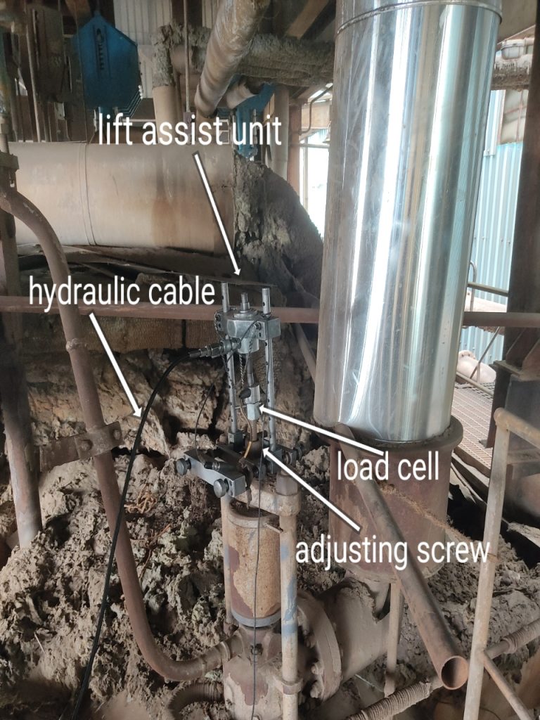
Trevi test is use for set pressure of safety valve with online while safety valve in service without adding pressure in whole system approaching the set pressure. Trevi test kit use the Hydraulic lift assist device to help pull spindle of safety valve to overcome spring force without increasing pressure in a system.
In early time in power plant we were not using trevi test for checking the pressure of safety valve instate of that we increase the pressure of system till the safety valve will not pop up than by comparing the control room valve pressure data we can set the pressure by tightening or loose the adjusting screw. But this method can be risky as well as time consuming and it can be reason of generation lose in the power plant.
Ask Running line pressure to operation department and enter that pressure in software, Calculate the pulled force from above formula then enter it in software then operate pressure applying switch that plot the graph in software the first deflection in the graph indicates the operate value of safety valve if this value is more then set value than we open lock nut of safety valve then tight adjusting screw if the value is less then set value than we open lock nut of safety valve then lose adjusting screw then tight lock nut, then take second trial to set the setting pressure.
A rope appx. 6-7 meters with a hook one end should be attached to the valve lifting lever before starting the pressure rise. It will help in operating the lever to avoid chattering & over pressure
Safety valves blow down should be set more than required, as blow down percentage decreases as the steam temperature increases. An approximate rule is to add 0.5% of set pressure to the blow down for each 56.5 °C rise in SH steam temperature.
If a Super heater safety valve lifts at 189.5 kg/cm2 & reseats at 180 kg/cm2 at the temperature of 400 deg c, then calculate the blowdown calculation at 540 deg c

A: Maintenance should be performed on a regular basis. An initial inspection interval of no longer than 12 months is recommended. The user must establish an appropriate inspection interval depending on the service conditions, the condition of the valve and the level of performance desired.
The ASME Boiler and Pressure Vessel Code does not require nor address testing installed valves. The only thing the code states are design and installation requirements, such as some valves must have a lifting lever. For instance for Section VIII:
“Each pressure relief valve on air, water over 140° F, or steam service shall have a substantial lifting device which when activated will release the seating force on the disk when the pressure relief valve is subjected to a pressure of at least 75% of the set pressure of the valve.”
A: This drain hole is required on some models by the ASME Boiler and Pressure Vessel Code. It is intended to prevent any condensate from accumulating in the body that may freeze or corrode internal valve parts and prevent the valve from opening. The drain hole should be piped away to safely dispose of any discharge or condensate.
A: This is often a confusing topic. The correct installation often looks backwards from what appears to be correct. A paper instruction tag illustrating the proper connection is attached to each valve. Vacuum valves should have the NPT threads that are cast integral to the body attached to the vacuum source. See the assembly drawing for additional clarification.
A: Typically, the valve should be nameplate set to open at the MAWP (Maximum Allowable Working Pressure) of the vessel the valve is intended to protect. There is a tolerance to actual set pressure, which means a valve set at 100 psig nameplate may open slightly above or below 100 psig. Consult the current ASME Boiler and Pressure Vessel Code for tolerance classes and special situations when the set pressure may be different than the MAWP.
A: It is normal for spring-operated safety valves to exhibit leakage or simmer/warn, as the system operating pressure approaches the nameplate set pressure, typically in the 80%-90% range of nameplate set pressure. The ASME Boiler and Pressure Vessel Code does not require a specific seat tightness requirement. A certain level of leakage is allowed per manufacturers’ literature and API-527 Seat Tightness Performance Standards, both of which can be found in the Technical Reference Catalog and in the Data Supplement, summarized as follows:
API-527 Standard Seat Tightness Performance: A Functional Test Report (FTR) is automatically provided for valves ordered to API-527. See API 527 for complete details.
A: Maintain a minimum operating gap of 10% between the system operating pressure and the safety valve’s nameplate set pressure. Since direct spring-operated safety valves may “simmer” or “warn” at 90% of the nameplate set pressure, and since the factory standard leak test is performed at 80% of nameplate set pressure, better seat tightness performance can be expected with an operating gap of 20%.
Variance of set pressure is allowed, i.e., a Section VIII air valve with a nameplate of 100 psig set pressure may open from 97 psig to 103 psig, but will be factory set around 102 psig.
Gage issues may lead to incorrect reporting of set pressure. Ensure the gage is within calibration and is accurate for the pressure being measured. Rapid increases in system pressure (more than 2 psig/second, water hammer, reciprocating pumps) can make the valve appear to be opening early because the gage cannot accurately report the pressure to which the valve is exposed.
A: Yes. Section I valves have more stringent setting blowdown requirements and may be used in Section VIII steam applications since they meet all the requirements as specified in Section VIII UG-125(a) “Pressure Relief Devices,” which states pressure relief devices must be “in accordance with the requirements of UG-125 through UG-137.” In addition, UG-125(b) actually specifies that even unfired steam boilers MUST use a Section I pressure relief device.
A: Section VIII UG-136(a)(3) states, “Each pressure relief valve on air, water over 140° F (60° C), or steam service shall have a substantial lifting device which when activated will release the seating force on the disk when the pressure relief valve is subjected to a pressure of at least 75% of the set pressure of the valve.”
The user has a documented procedure and an associated implementation program for the periodic removal of the pressure relief valves for inspection and testing, and repair as necessary.
A: Back pressure reduces set pressure on a one-to-one basis, i.e., a valve set at 100 psig subjected to a backpressure at the outlet of 10 psig will not actuate until system pressure reaches 110 psig. Back pressure drastically reduces capacity; typically backpressure of 10% of set pressure will decrease capacity by 50%. Specific capacity reduction should be determined by the user on a case-by-case basis by flow testing. Back pressure in excess of 10% of set pressure is not recommended.
A: The ASME Boiler and Pressure Vessel Code does not have blowdown requirements for Section VIII (or non-code) valves. Blowdown may vary from less than 2% to more than 50%, depending on many factors including: valve design, dimensional tolerance variation, where the set pressure falls in the set pressure range of a spring, spring rate/force ratio, warn ring/guide settings, etc. Typical blowdown for most valves is 15% to 30%, but cannot be guaranteed. VM
Jim Knox is president, Allied Valve, Inc. (www.alliedvalve.com), a valve repair service company and supplier of Tyco Kunkle and Dresser Consolidated safety valves in the Midwest. Reach him at knoxj@alliedvalveinc.com.
ValvTechnologies and Severn Glocon have reached a partnership agreement that will see collaboration between two of the world’s leading engineering and manufacturing companies specializing in innovative, high-end, severe-service valves.
This article outlines the challenges of lifting large valve assemblies weighing several tons and illustrates the industrial rigging equipment and lifting operations typically used for these valves.

1 and 2, the safety flap testing device for a safety valve for a power plant and a chemical factory according to the present invention is provided with a safety valve 1 for preventing the safety valve 1 from being detached from a facility or an apparatus of a power plant and a chemical plant. When the vibration within the work area exceeds the set value or when the atmospheric pressure is out of the set range when testing whether popping occurs at the set pressure, the driving of the hydraulic pump 10 is stopped to prevent the flapping test in an unstable environment, The application pressure of the hydraulic pump 10 for inducing the set pressure is linearly increased in proportion to the time and the safety valve 1 is tested. When the flapping is sensed, the operation of the hydraulic pump 10 is stopped, It is possible to prevent the failure of the safety valve 1, the load cell or the hydraulic pump 10 due to the failure.
The safety flapping test apparatus for a power plant and a chemical plant according to the present invention is for testing whether a safety valve 1 installed in a facility such as a pressure vessel or a piping or a piping of a power plant and a chemical plant is popped at a set pressure, A hydraulic pump (10) having a control valve (10a) for transmitting hydraulic pressure to a hydraulic jack (12) for raising an operating rod (2) of a safety valve (1) installed in a workshop of a chemical plant and controlling the flow rate; A pressure sensor (20) for measuring the discharge pressure of the hydraulic pump (10); A load cell 30 for converting a load applied between the operating rod 2 and the hydraulic jack 12 of the safety valve 1 into an electrical load signal; A vibration sensor (37) for detecting vibration in the work space; An atmospheric pressure sensor 39 for measuring the atmospheric pressure inside the workplace; The control unit controls the hydraulic


 8613371530291