
boiler safety valve pressure setting in stock
In order to ensure that the maximum allowable accumulation pressure of any system or apparatus protected by a safety valve is never exceeded, careful consideration of the safety valve’s position in the system has to be made. As there is such a wide range of applications, there is no absolute rule as to where the valve should be positioned and therefore, every application needs to be treated separately.
A common steam application for a safety valve is to protect process equipment supplied from a pressure reducing station. Two possible arrangements are shown in Figure 9.3.3.
The safety valve can be fitted within the pressure reducing station itself, that is, before the downstream stop valve, as in Figure 9.3.3 (a), or further downstream, nearer the apparatus as in Figure 9.3.3 (b). Fitting the safety valve before the downstream stop valve has the following advantages:
• The safety valve can be tested in-line by shutting down the downstream stop valve without the chance of downstream apparatus being over pressurised, should the safety valve fail under test.
• When setting the PRV under no-load conditions, the operation of the safety valve can be observed, as this condition is most likely to cause ‘simmer’. If this should occur, the PRV pressure can be adjusted to below the safety valve reseat pressure.
Indeed, a separate safety valve may have to be fitted on the inlet to each downstream piece of apparatus, when the PRV supplies several such pieces of apparatus.
• If supplying one piece of apparatus, which has a MAWP pressure less than the PRV supply pressure, the apparatus must be fitted with a safety valve, preferably close-coupled to its steam inlet connection.
• If a PRV is supplying more than one apparatus and the MAWP of any item is less than the PRV supply pressure, either the PRV station must be fitted with a safety valve set at the lowest possible MAWP of the connected apparatus, or each item of affected apparatus must be fitted with a safety valve.
• The safety valve must be located so that the pressure cannot accumulate in the apparatus viaanother route, for example, from a separate steam line or a bypass line.
It could be argued that every installation deserves special consideration when it comes to safety, but the following applications and situations are a little unusual and worth considering:
• Fire - Any pressure vessel should be protected from overpressure in the event of fire. Although a safety valve mounted for operational protection may also offer protection under fire conditions,such cases require special consideration, which is beyond the scope of this text.
• Exothermic applications - These must be fitted with a safety valve close-coupled to the apparatus steam inlet or the body direct. No alternative applies.
• Safety valves used as warning devices - Sometimes, safety valves are fitted to systems as warning devices. They are not required to relieve fault loads but to warn of pressures increasing above normal working pressures for operational reasons only. In these instances, safety valves are set at the warning pressure and only need to be of minimum size. If there is any danger of systems fitted with such a safety valve exceeding their maximum allowable working pressure, they must be protected by additional safety valves in the usual way.
In order to illustrate the importance of the positioning of a safety valve, consider an automatic pump trap (see Block 14) used to remove condensate from a heating vessel. The automatic pump trap (APT), incorporates a mechanical type pump, which uses the motive force of steam to pump the condensate through the return system. The position of the safety valve will depend on the MAWP of the APT and its required motive inlet pressure.
This arrangement is suitable if the pump-trap motive pressure is less than 1.6 bar g (safety valve set pressure of 2 bar g less 0.3 bar blowdown and a 0.1 bar shut-off margin). Since the MAWP of both the APT and the vessel are greater than the safety valve set pressure, a single safety valve would provide suitable protection for the system.
However, if the pump-trap motive pressure had to be greater than 1.6 bar g, the APT supply would have to be taken from the high pressure side of the PRV, and reduced to a more appropriate pressure, but still less than the 4.5 bar g MAWP of the APT. The arrangement shown in Figure 9.3.5 would be suitable in this situation.
Here, two separate PRV stations are used each with its own safety valve. If the APT internals failed and steam at 4 bar g passed through the APT and into the vessel, safety valve ‘A’ would relieve this pressure and protect the vessel. Safety valve ‘B’ would not lift as the pressure in the APT is still acceptable and below its set pressure.
It should be noted that safety valve ‘A’ is positioned on the downstream side of the temperature control valve; this is done for both safety and operational reasons:
Operation - There is less chance of safety valve ‘A’ simmering during operation in this position,as the pressure is typically lower after the control valve than before it.
Also, note that if the MAWP of the pump-trap were greater than the pressure upstream of PRV ‘A’, it would be permissible to omit safety valve ‘B’ from the system, but safety valve ‘A’ must be sized to take into account the total fault flow through PRV ‘B’ as well as through PRV ‘A’.
A pharmaceutical factory has twelve jacketed pans on the same production floor, all rated with the same MAWP. Where would the safety valve be positioned?
One solution would be to install a safety valve on the inlet to each pan (Figure 9.3.6). In this instance, each safety valve would have to be sized to pass the entire load, in case the PRV failed open whilst the other eleven pans were shut down.
If additional apparatus with a lower MAWP than the pans (for example, a shell and tube heat exchanger) were to be included in the system, it would be necessary to fit an additional safety valve. This safety valve would be set to an appropriate lower set pressure and sized to pass the fault flow through the temperature control valve (see Figure 9.3.8).

When I teach my steam classes, I ask the attendees, "Do you test the pop safety valve?" Most do not. When I ask why, they tell me the same reason; the safety valve will leak. I joke during the classes that you do not want to test the pop safety valve on a Friday afternoon because it will almost certainly leak. I then ask, Do you check the low water cutoff? They look at me like I have a third eye and say they always check the low water cutoff. If you test the low water cutoff, you should test the pop safety valve. It is the last line of defense against a potential catastrophe. One of the things I do when performing a boiler service call is to explain the duty of the pop safety valve and ask the customer if they would like to have it tested. I explain that it could leak and if they refuse to test it, I will notate it on my service call in case something happens. In this way, my company is protected.
The best way to understand the pop safety valve is to read the instructions which came with the valve. I don"t have a life, and while you are watching the Masked Singer, I read O & M manuals. I know, I"m weird. I figure it"s my job to share things I find while reading these page-turners. The manufacturer hides all sorts of useful tidbits on the installation and maintenance of their valve. I have enclosed some information I gleaned while reading the instructions for a Conbraco/Apollo pop safety valve.
The valve must be mounted in a vertical, upright position directly to a clean, tapped opening in the top of the boiler. I see many safety valves installed horizontally and wonder if that voids the warranty. There should be no restrictions or valves in the piping to or from the safety valve. The installation instructions require the discharge piping to be schedule 40 pipe. They specifically say not to use schedule 80 pipe, which is 50% thicker than schedule 40 pipe. Many installers use copper tubing for the discharge, which does not meet the instructions. The other thing which confuses me the manufacturer instructs you not to use a pipe wrench to install the safety valve. I would wager 99% of all valves are installed using a pipe wrench. I wonder what kind of valve they want you to use.
I consult the pop safety manufacturer or the building insurance company to determine the frequency of tests. Apollo recommends quarterly testing using the Try Lever Test unless the valve is located in a severe service condition, and then it should be done more often. They further state the pop safety valve should have a Pressure Test annually before the heating season or at the end of any non-service period. This test will check your courage as you have to jump out the pressure controls and watch the operation of the boiler as the pressure builds. If the pop safety valve opens at the set pressure, the valve is working properly. This is not a test a novice should do alone.
Apollo suggests checking the pop safety valve at or near the maximum operating pressure by holding the test lever fully open for at least 5 seconds and letting it pop closed. On a low-pressure steam system, the pop safety valve is set for 15 psi. I like to run the boiler steam pressure up to 12 psi or higher to check the pop safety valve. After the test, I drop it to the operating pressure the owner requires. If the valve does not open, the boiler should be shut down until it is checked by a licensed contractor or qualified service person.
The pop safety manufacturer requires a minimum pressure differential of five psi between the pressure relief valve set pressure and the boiler operating pressure. It further states, Under no circumstances should the margin be less than five psig. On a low-pressure steam boiler, the pop safety valve will be set for 15 psi. That means the boiler steam pressure should be ten psi or lower. In breweries, it is common to see the boiler pressure set at 12-14 psi. This is less than the five psi differential and could create a dangerous condition.
Years ago, it was not uncommon to read news about tragic boiler explosions, sometimes resulting in mass destruction. Today, boilers are equipped with important safety devises to help protect against these types of catastrophes. Let’s take a look at the most critical of these devices: the safety valve.
The safety valve is one of the most important safety devices in a steam system. Safety valves provide a measure of security for plant operators and equipment from over pressure conditions. The main function of a safety valve is to relieve pressure. It is located on the boiler steam drum, and will automatically open when the pressure of the inlet side of the valve increases past the preset pressure. All boilers are required by ASME code to have at least one safety valve, dependent upon the maximum flow capacity (MFC) of the boiler. The total capacity of the safety valve at the set point must exceed the steam control valve’s MFC if the steam valve were to fail to open. In most cases, two safety valves per boiler are required, and a third may be needed if they do not exceed the MFC.
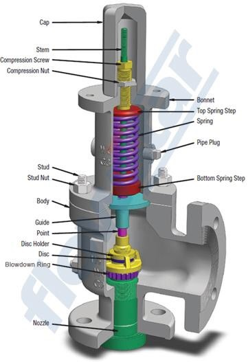
There are three main parts to the safety valve: nozzle, disc, and spring. Pressurized steam enters the valve through the nozzle and is then threaded to the boiler. The disc is the lid to the nozzle, which opens or closes depending on the pressure coming from the boiler. The spring is the pressure controller.
As a boiler starts to over pressure, the nozzle will start to receive a higher pressure coming from the inlet side of the valve, and will start to sound like it is simmering. When the pressure becomes higher than the predetermined pressure of the spring, the disc will start to lift and release the steam, creating a “pop” sound. After it has released and the steam and pressure drops below the set pressure of the valve, the spring will close the disc. Once the safety valve has popped, it is important to check the valve to make sure it is not damaged and is working properly.
A safety valve is usually referred to as the last line of safety defense. Without safety valves, the boiler can exceed it’s maximum allowable working pressure (MAWP) and not only damage equipment, but also injure or kill plant operators that are close by. Many variables can cause a safety valve on a boiler to lift, such as a compressed air or electrical power failure to control instrumentation, or an imbalance of feedwater rate caused by an inadvertently shut or open isolation valve.
Once a safety valve has lifted, it is important to do a complete boiler inspection and confirm that there are no other boiler servicing issues. A safety valve should only do its job once; safety valves should not lift continuously. Lastly, it is important to have the safety valves fully repaired, cleaned and recertified with a National Board valve repair (VR) stamp as required by local code or jurisdiction. Safety valves are a critical component in a steam system, and must be maintained.
All of Nationwide Boiler’s rental boilers include on to two safety valves depending on the size; one set at design pressure and the other set slightly higher than design. By request, we can reset the safeties to a lower pressure if the application requires it. In addition, the valves are thoroughly checked after every rental and before going out to a new customer, and they are replaced and re-certified as needed.
(a) Qualifications of individual who adjusts. Safety relief valves shall be set and adjusted by a competent person who is thoroughly familiar with the construction and operation of the valve being set.
(b) Opening pressures. At least one safety relief valve shall be set to open at a pressure not exceeding the MAWP. Safety relief valves shall be set to open at pressures not exceeding 6 psi above the MAWP.
(c) Setting procedures. When setting safety relief valves, two steam gauges shall be used, one of which must be so located that it will be in full view of the persons engaged in setting such valves; and if the pressure indicated by the gauges varies more than 3 psi they shall be removed from the boiler, tested, and corrected before the safety relief valves are set. Gauges shall in all cases be tested immediately before the safety relief valves are set or any change made in the setting. When setting safety relief valves, the water level shall not be higher than
(d) Labeling of lowest set pressure. The set pressure of the lowest safety relief valve shall be indicated on a tag or label attached to the steam gauge so that it may be clearly read while observing the steam gauge.

Boiler safety valve setting procedure is given in this article. To make the content easier to understand and also to make reader to understand as how this important activity is done.
As an engineer onboard you will be required to set the safety valve after each boiler survey. It is a process which needs precision and skill also. Let’s check the stepwise details of the procedure you need to follow while setting the valve.
2) Boiler is ready to be fired. Make sure that the steam blow off line after the safety valve, have a drain and it should be unclogged and should have free passage.
7) Screw down the compression nut little bit more than the previous distance. If you don’t have previous reading, then it will require little bit more attempts before you can actually set the valve.
8) Now let’s say you have to set valve at 9 bar. So, raise the pressure slowly. Just before the 9 bar, like 8.8 or 8.9, you will start seeing little bit of steam coming out of the safety valve.
Note: If you safety valve lifts at 10 bar instead of 9, then don’t try to set it down at the same time. Lower the pressure to 7 bar or something and then adjust the compression nut and then again raise the pressure to 9 bar. Otherwise you get all the wrong adjustment.
14) After both valves are set, they usually have some difference like 0.3 bar. This is not intentional and comes due to the fact that precise and similar adjust of both the valves is not same.
Tired of keeping track of your valve inventory’s annual certification records? We offer complete management of your safety relief valves. With an inventory of repair parts and in stock relief valves of all sizes, we can respond to any customer emergency. We offer annual certification services as well as repair of all major brands, including Kunkle, Conbraco, Consolidated, Dresser, Apollo and more.

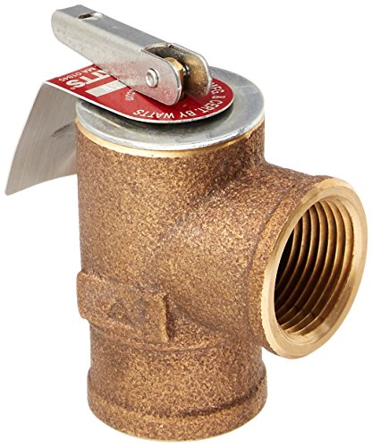
Series 174A Boiler Pressure Relief Valves are used in hot water heating and domestic supply boiler applications to protect against excessive pressures on all types of hot water heating supply boiler equipment. They have a bronze body construction with NPT threaded female inlet and NPT threaded female outlet (drain) connections, non-metallic disc-to-metal seating, stainless steel spring, and test lever. Series 174A resists corrosive water conditions, sticking, and freezing, and it prevents water and sediment from being trapped in the seat. It is designed for emergency safety relief and shall not be used as an operating control. Standard Pressure Setting: 30psi (206.9 kPa). Pressure Range: In 5psi (34.5 kPa) increments from 30 to 150psi (2 to 10 bar) with corresponding high ratings from 650,000 to 14,370,000 BTU/hr.
%20Cross-Section.png)
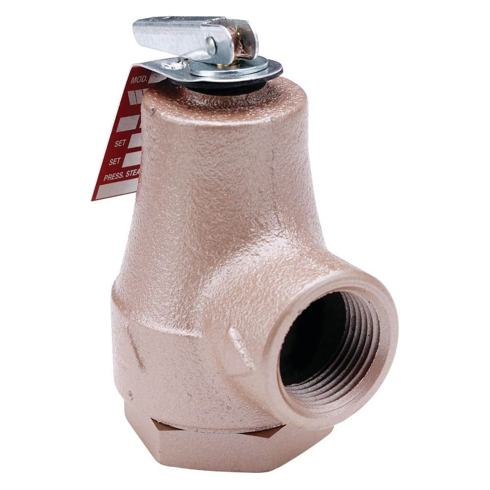
This 1 inch boiler pressure relief valve is used in hot water space heating boiler applications to protect against excessive pressure on all types of hot water space heating boiler equipment. It consists of an iron body construction with expanded outlet drain connections for hot water space heating boilers, non-metallic disc-to-metal seating, stainless steel spring, and test lever. It offers large discharge capacity, resists corrosive water conditions, resists sticking and freezing, and prevents water and sediment from being trapped in the seat. It is designed for emergency safety relief, not as an operating control. The pressure relief is set at 30 psi ( 206.8 kPa) with corresponding high pressure ratings up to 1,300,000 BTU/hr.


 8613371530291