
boiler safety valve regulations manufacturer

Boiler explosions have been responsible for widespread damage to companies throughout the years, and that’s why today’s boilers are equipped with safety valves and/or relief valves. Boiler safety valves are designed to prevent excess pressure, which is usually responsible for those devastating explosions. That said, to ensure that boiler safety valves are working properly and providing adequate protection, they must meet regulatory specifications and require ongoing maintenance and periodic testing. Without these precautions, malfunctioning safety valves may fail, resulting in potentially disastrous consequences.
Boiler safety valves are activated by upstream pressure. If the pressure exceeds a defined threshold, the valve activates and automatically releases pressure. Typically used for gas or vapor service, boiler safety valves pop fully open once a pressure threshold is reached and remain open until the boiler pressure reaches a pre-defined, safe lower pressure.
Boiler relief valves serve the same purpose – automatically lowering boiler pressure – but they function a bit differently than safety valves. A relief valve doesn’t open fully when pressure exceeds a defined threshold; instead, it opens gradually when the pressure threshold is exceeded and closes gradually until the lower, safe threshold is reached. Boiler relief valves are typically used for liquid service.
There are also devices known as “safety relief valves” which have the characteristics of both types discussed above. Safety relief valves can be used for either liquid or gas or vapor service.
Nameplates must be fastened securely and permanently to the safety valve and remain readable throughout the lifespan of the valve, so durability is key.
The National Board of Boiler and Pressure Vessel Inspectors offers guidance and recommendations on boiler and pressure vessel safety rules and regulations. However, most individual states set forth their own rules and regulations, and while they may be similar across states, it’s important to ensure that your boiler safety valves meet all state and local regulatory requirements.
The National Board published NB-131, Recommended Boiler and Pressure Vessel Safety Legislation, and NB-132, Recommended Administrative Boiler and Pressure Vessel Safety Rules and Regulationsin order to provide guidance and encourage the development of crucial safety laws in jurisdictions that currently have no laws in place for the “proper construction, installation, inspection, operation, maintenance, alterations, and repairs” necessary to protect workers and the public from dangerous boiler and pressure vessel explosions that may occur without these safeguards in place.
The documents are meant to be used as a guide for developing local laws and regulations and also may be used to update a jurisdiction’s existing requirements. As such, they’re intended to be modifiable to meet any jurisdiction’s local conditions.
The American Society of Mechanical Engineers (ASME) governs the code that establishes guidelines and requirements for safety valves. Note that it’s up to plant personnel to familiarize themselves with the requirements and understand which parts of the code apply to specific parts of the plant’s steam systems.
High steam capacity requirements, physical or economic constraints may make the use of a single safety valve impossible. In these cases, using multiple safety valves on the same system is considered an acceptable practice, provided that proper sizing and installation requirements are met – including an appropriately sized vent pipe that accounts for the total steam venting capacity of all valves when open at the same time.
The lowest rating (MAWP or maximum allowable working pressure) should always be used among all safety devices within a system, including boilers, pressure vessels, and equipment piping systems, to determine the safety valve set pressure.
Avoid isolating safety valves from the system, such as by installing intervening shut-off valves located between the steam component or system and the inlet.
Contact the valve supplier immediately for any safety valve with a broken wire seal, as this indicates that the valve is unsafe for use. Safety valves are sealed and certified in order to prevent tampering that can prevent proper function.
Avoid attaching vent discharge piping directly to a safety valve, which may place unnecessary weight and additional stress on the valve, altering the set pressure.

(1) Boiler safety valves and safety relief valves must be as indicated in PG-67 through PG-73 of section I of the ASME Boiler and Pressure Vessel Code (incorporated by reference; see 46 CFR 52.01-1) except as noted otherwise in this section.
(3) On river steam vessels whose boilers are connected in batteries without means of isolating one boiler from another, each battery of boilers shall be treated as a single boiler and equipped with not less than two safety valves of equal size.
(4) (Modifies PG-70.) The total rated relieving capacity of drum and superheater safety valves as certified by the valve manufacturer shall not be less than the maximum generating capacity of the boiler which shall be determined and certified by the boiler manufacturer. This capacity shall be in compliance with PG-70 of section I of the ASME Boiler and Pressure Vessel Code.
(5) In the event the maximum steam generating capacity of the boiler is increased by any means, the relieving capacity of the safety valves shall be checked by an inspector, and, if determined to be necessary, valves of increased relieving capacity shall be installed.
(6) (Modifies PG-67.) Drum safety valves shall be set to relieve at a pressure not in excess of that allowed by the Certificate of Inspection. Where for any reason this is lower than the pressure for which the boiler was originally designed and the revised safety valve capacity cannot be recomputed and certified by the valve manufacturer, one of the tests described in PG-70(3) of section I of the ASME Boiler and Pressure Vessel Code shall be conducted in the presence of the Inspector to insure that the relieving capacity is sufficient at the lower pressure.
(8) Lever or weighted safety valves now installed may be continued in use and may be repaired, but when renewals are necessary, lever or weighted safety valves shall not be used. All such replacements shall conform to the requirements of this section.
(1) (Modifies PG-68.) Superheater safety valves shall be as indicated in PG-68 of section I of the ASME Boiler and Pressure Vessel Code except as noted otherwise in this paragraph.
(2) The setting of the superheater safety valve shall not exceed the design pressure of the superheater outlet flange or the main steam piping beyond the superheater. To prevent damage to the superheater, the drum safety valve shall be set at a pressure not less than that of the superheater safety valve setting plus 5 pounds minimum plus approximately the normal load pressure drop through the superheater and associated piping, including the controlled desuperheater if fitted. See also § 52.01-95(b) (1).
(3) Drum pilot actuated superheater safety valves are permitted provided the setting of the pilot valve and superheater safety valve is such that the superheater safety valve will open before the drum safety valve.
(1) (Modifies PG-71.) Safety valves shall be installed as indicated in PG-71 of section I of the ASME Boiler and Pressure Vessel Code except as noted otherwise in this paragraph.
(2) The final setting of boiler safety valves shall be checked and adjusted under steam pressure and, if possible, while the boiler is on the line and the steam is at operating temperatures, in the presence of and to the satisfaction of a marine inspector who, upon acceptance, shall seal the valves. This regulation applies to both drum and superheater safety valves of all boilers.
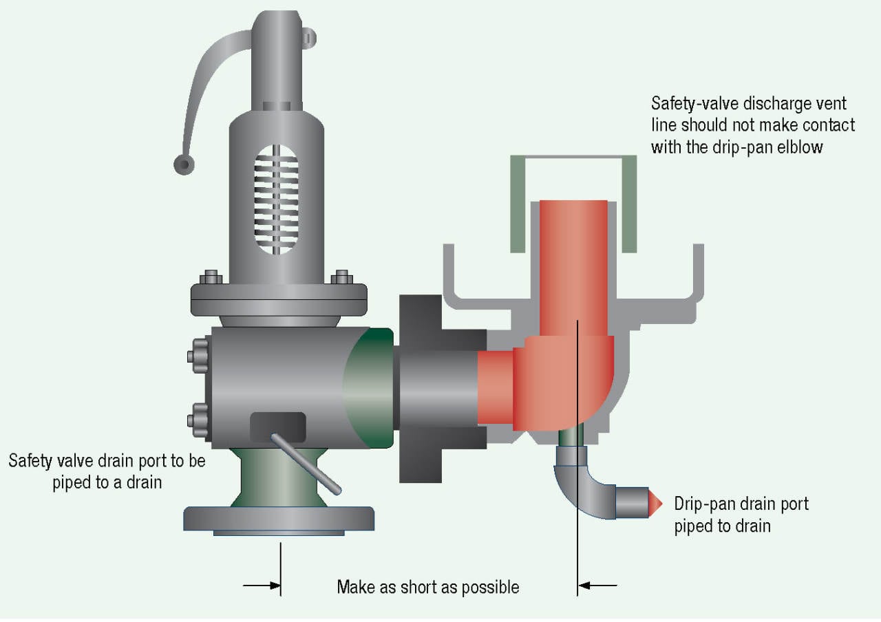
(3) The safety valve body drains required by PG-71 of section I of the ASME Boiler and Pressure Vessel Code shall be run as directly as possible from the body of each boiler safety valve, or the drain from each boiler safety valve may be led to an independent header common only to boiler safety valve drains. No valves of any type shall be installed in the leakoff from drains or drain headers and they shall be led to suitable locations to avoid hazard to personnel.
(1) (Modifies PG-72.) The operation of safety valves shall be as indicated in PG-72 of section I of the ASME Boiler and Pressure Vessel Code except as noted in paragraph (d)(2) of this section.
(2) (Modifies PG-73.) The lifting device required by PG-73.1.3 of section I of the ASME Boiler and Pressure Vessel Code shall be fitted with suitable relieving gear so arranged that the controls may be operated from the fireroom or engineroom floor.

Cast-iron boilers may be used in steam heating or hot water heating applications within the scope and service restrictions of ASME BPV Code Section IV. ASME BPV Code Section IV service restrictions limit steam boilers to pressures not exceeding 15 psi and hot water boilers to pressures not exceeding 160 psi and/or temperatures not exceeding 250°F.
One Piece – a single casting with no assembly joints. Another term used to describe this design is monobloc. This type of cast-iron boiler is usually small in size.
Sectional boilers are typically assembled with tapered connections called push nipples or elastomeric-type gaskets between the sections to seal the water-containing chambers. Another type of assembly uses external headers to connect the water containing chambers.
Cast-iron boilers can be found in almost any application where heating boilers are used. They are popular replacements for large welded steel boilers which may have been installed as the building was being constructed. Cast-iron sectional boilers can usually be installed in existing boiler rooms by moving the individual sections through doors or window openings. A very large boiler can be assembled in this manner without modifications to the building structure.
There will be two pieces of information missing from a cast-iron boiler nameplate: a National Board registration number and the year built. Cast-iron boilers are not registered with the National Board, and ASME BPV Code Section IV makes no provisions for a year of construction to appear on the nameplate. Since most inspection forms ask for a year of construction, the inspector will have to estimate. If the boiler is original to the building, the age of the building would directly correspond to the age of the boiler. If the boiler is a replacement, the inspector will have to question the owner to determine its age.
Cast-iron boilers may be used in steam heating or hot water heating applications within the scope and service restrictions of ASME BPV CodeSection IV. ASME BPV CodeSection IV service restrictions limit steam boilers to pressures not exceeding 15 psi and hot water boilers to pressures not exceeding 160 psi and/or temperatures not exceeding 250°F.
Steam boilers must have at least one safety valve with a set pressure not to exceed 15 psi. The safety valve inlet must not be smaller than NPS 1/2 nor larger than NPS 4-1/2.
Hot-water boilers must have at least one safety relief valve with a set pressure at or below the maximum allowable working pressure (MAWP) marked on the boiler. The safety relief valve inlet must not be smaller than NPS 3/4 nor larger than NPS 4-1/2. The minimum relieving capacity of safety or safety relief valves must equal or exceed the maximum output of the boiler. Cast-iron boilers constructed since 1943 will have information on the nameplate indicating the minimum required safety or safety relief valve capacity. Cast-iron boilers constructed prior to 1943 may not have that information. In those circumstances, the inspector must estimate the maximum output of the boiler. Gas or oil burners generally have a rating plate or label containing the Btu output of the burner. A generally applied guideline for older boilers is to use 80% of the maximum burner output as the maximum boiler output. Boilers fired with solid fuel such as coal or wood will be extremely difficult to estimate, since there is no way for the inspector to calculate the cast-iron boiler heating surface. In those cases, the inspector should request the boiler owner/user perform an accumulation test in accordance with HG-512(a), or a maximum burned fuel evaluation in accordance with HG-512(b) and Appendix B. These procedures should only be used if the safety or safety relief valve capacity is in doubt.
two pressure controls (if the boiler is automatically fired); one is considered the operating control and the other is considered the high-limit control (Note: some jurisdictions require the high-limit control be equipped with a manual reset switch) (HG-605);
an automatic low-water fuel cutoff – if the boiler is automatically fired (Note: some jurisdictions require an additional low-water fuel cutoff with a manual reset switch) (HG-606).
two temperature controls (if the boiler is automatically fired); one is considered the operating control and the other is considered the high-limit control (Note: some jurisdictions require the high limit control be equipped with a manual reset switch) (HG-613);
an automatic low-water fuel cutoff – if the boiler is automatically fired and has a heat input greater than 400,000 Btu/hr (Note: some jurisdictions require an additional low water fuel cutoff with a manual reset switch)(HG-614)
Clearances on the front, rear, sides, and top of all cast-iron boilers for operation, maintenance, and inspection shall meet jurisdictional requirements. If no jurisdictional requirements exist, then the boiler manufacturer"s requirements shall be met.
All cast-iron boilers should be installed on foundations or supports suitable for the weight of the boiler and its contents. The foundation or support must also be unaffected by the heat of the operating boiler.
Although most jurisdictions do not require inspection of the piping associated with an ASME BPV CodeSection IV boiler, there are some installation requirements in ASME BPV Code Section IV the inspector should review. Please see HG-703 and HG-705.
Steam boilers must have at least one safety valve with a set pressure not to exceed 15 psi. The safety valve inlet must not be smaller than NPS 1/2 nor larger than NPS 4-1/2.
Cast-iron boilers typically have a few inherent problems. The inspector should always look for water leaks at the connecting joints of sectional boilers. The inspector should request the removal of the sheet metal casing any time there is evidence of leakage and the leakage cannot be traced to an external source.
The most common problem associated with cast-iron boilers is cracking due to overheating or thermal shock. Overheating occurs when the boiler is allowed to operate with low-water conditions or poor circulation caused by sludge concentrated in the lower water passages of the boiler. Thermal shock can occur when a boiler is overheated and cold water is added in an attempt to raise the water level. Under those circumstances, cracking is usually the least that can happen. The worst that can happen is an explosion which shatters the cast-iron boiler into many pieces and cause destruction and injury.
Sectional cast-iron boilers use long rods, threaded on both ends, called draw bolts. It is not unusual for these draw bolts to appear loose when the boiler is cold. When the boiler is operating, the heat will cause the boiler to expand which tightens the draw bolts. A loose draw bolt on a hot boiler should be investigated by a competent cast-iron boiler service/repair company.
Cast-iron boilers typically have a few inherent problems. The inspector should always look for water leaks at the connecting joints of sectional boilers. The inspector should request the removal of the sheet metal casing any time there is evidence of leakage and the leakage cannot be traced to an external source.
Upon entering the boiler room, the inspector should perform a general assessment of the boiler, piping, controls, fuel system, and combustion air supply. The inspector should then:
compare the safety or safety relief valve nameplate data (set pressure and relieving capacity) with the boiler nameplate to ensure the safety or safety relief valve is adequate for this installation;
check the thermometer reading on hot water boilers (if there is a reason to question the accuracy of the thermometer, it should be replaced or recalibrated);
check the water gage glass to ensure it provides a clear indication of the water level in a steam boiler. (Please see the National Board Inspector Guide for Water Level Controls and Devices);
look for evidence of overheating (this may be difficult to detect on a cast-iron boiler; warped external sheet metal casings with scorched paint is usually a reliable indicator);
inspect the fuel-burning apparatus as required by the jurisdiction (for example, some jurisdictions mandate compliance with ASME Standard CSD-1, Controls & Safety Devices for Automatically Fired Boilers).
Internal inspections of cast-iron boilers can prove to be difficult or almost impossible. Threaded plugs on the cast iron boiler could be removed, but the inspector will see very little past the immediate vicinity of the opening on many cast iron boiler designs. In addition, the threaded plugs are sometimes heavily corroded which virtually "welds" them to the cast iron. Removal of threaded plugs in this condition may damage the cast iron irreparably. Some boilers may have valves installed in the lowest threaded openings of the boiler to facilitate draining and/or flushing of the boiler. If valves are present, the inspector can ask for them to be opened briefly to observe the condition of the water. If no water is present when the valves are opened, this could be an indication the lowest portion of the boiler is filled with sludge. The inspector is advised to follow the jurisdiction"s requirements for internal inspections of cast-iron boilers.
Threaded plugs in the piping connecting a water gage glass, water column, and low-water fuel cutoff to a steam boiler must be removed to allow inspection of the piping to ensure there is no blockage.

(a) Each power boiler, nuclear boiler, and high temperature water boiler shall have safety valves or pressure relieving devices constructed, stamped and installed in accordance with the applicable section of the Code, except:
(2) Upon written request by the employer, the Division may permit three-way two-port valves to be installed under two safety valves, each with the required relieving capacity, provided they are so installed that both safety valves cannot be closed off from the boiler at the same time and provided the three-way valve will permit at least full flow to the safety valve in service at all time.
(b) The user shall maintain all pressure relieving devices in good operating condition. Where the valves cannot be tested in service, the user shall maintain and make available to the inspector records showing the test dates and set pressure for such valves.
3. Change without regulatory effect inserting "(a)" immediately preceding the first paragraph and "(b)" immediately preceding the fourth paragraph, filed 1-24-91 pursuant to section 100, Title 1, California Code of Regulations (Register 91, No. 7).

Years ago, it was not uncommon to read news about tragic boiler explosions, sometimes resulting in mass destruction. Today, boilers are equipped with important safety devises to help protect against these types of catastrophes. Let’s take a look at the most critical of these devices: the safety valve.
The safety valve is one of the most important safety devices in a steam system. Safety valves provide a measure of security for plant operators and equipment from over pressure conditions. The main function of a safety valve is to relieve pressure. It is located on the boiler steam drum, and will automatically open when the pressure of the inlet side of the valve increases past the preset pressure. All boilers are required by ASME code to have at least one safety valve, dependent upon the maximum flow capacity (MFC) of the boiler. The total capacity of the safety valve at the set point must exceed the steam control valve’s MFC if the steam valve were to fail to open. In most cases, two safety valves per boiler are required, and a third may be needed if they do not exceed the MFC.
There are three main parts to the safety valve: nozzle, disc, and spring. Pressurized steam enters the valve through the nozzle and is then threaded to the boiler. The disc is the lid to the nozzle, which opens or closes depending on the pressure coming from the boiler. The spring is the pressure controller.
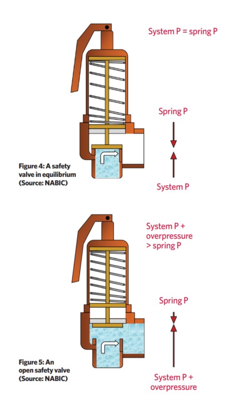
As a boiler starts to over pressure, the nozzle will start to receive a higher pressure coming from the inlet side of the valve, and will start to sound like it is simmering. When the pressure becomes higher than the predetermined pressure of the spring, the disc will start to lift and release the steam, creating a “pop” sound. After it has released and the steam and pressure drops below the set pressure of the valve, the spring will close the disc. Once the safety valve has popped, it is important to check the valve to make sure it is not damaged and is working properly.
A safety valve is usually referred to as the last line of safety defense. Without safety valves, the boiler can exceed it’s maximum allowable working pressure (MAWP) and not only damage equipment, but also injure or kill plant operators that are close by. Many variables can cause a safety valve on a boiler to lift, such as a compressed air or electrical power failure to control instrumentation, or an imbalance of feedwater rate caused by an inadvertently shut or open isolation valve.
Once a safety valve has lifted, it is important to do a complete boiler inspection and confirm that there are no other boiler servicing issues. A safety valve should only do its job once; safety valves should not lift continuously. Lastly, it is important to have the safety valves fully repaired, cleaned and recertified with a National Board valve repair (VR) stamp as required by local code or jurisdiction. Safety valves are a critical component in a steam system, and must be maintained.
All of Nationwide Boiler’s rental boilers include on to two safety valves depending on the size; one set at design pressure and the other set slightly higher than design. By request, we can reset the safeties to a lower pressure if the application requires it. In addition, the valves are thoroughly checked after every rental and before going out to a new customer, and they are replaced and re-certified as needed.

As a design engineer responsible for developing and specifying boilers, dryers, furnaces, heaters, ovens and other industrial heating equipment, you face a daunting labyrinth of standards and industry regulations. Regulatory bodies sound a bit like alphabet soup, with acronyms like UL, FM, CSA, UR, AGA, ASME, ANSI, IRI, CE and NFPA tossed about. This article will help explain a common task for many thermal processing equipment specifiers: meeting the requirements of key codes — including Underwriters Laboratories (UL), Factory Mutual Insurers (FM) and the National Fire Protection Association (NFPA) — for safety valve equipment used in process heating applications.
Key to designing safety into your fuel train configurations are familiar technologies such as safety shutoff valves and vent valves as well as visual-indication mechanisms and proof-of-closure switches.
Your design skills come into play with how you take advantage of the wide range of products available. You can mix and match solenoid and safety shutoff valves — within designs from catalytic reactors to multi-zone furnaces — to create easily installed, cost-effective solutions that comply with all necessary standards. (See table.)
Make sure, however, that you start with a good grasp of valve element fundamentals. For example, examining a proof-of-closure (POC) switch underlines how reliably modern valves can ensure combustion safety. The POC unit provides an electrical contact interlocked with the controller safety circuit. In a typical design, the switch is located at the bottom of the valve, positioned to trace the stroke of the valve disc. When the disc seal reaches the fully closed position, it triggers the mechanism to push down on the contact, closing it and triggering the unit’s visual indicator to show open or closed status. As a result, the operator can act with full confidence in situations where it is critical that a safety valve be safely closed.
To provide ease of installation, many users prefer valves with modular capabilities. For example, to reduce mounting complexity, you can choose modular gas safety shut-off valves — combining a solenoid valve with an electrohydraulic motorized valve for a compact double-valve footprint, a slow-open feature and high flow rates. An accompanying actuator can provide on/off or high/low/off firing rates as well as visual indication and proof of closure for compliance with most industry standards.
Also, you may want to look for valves that include useful features such as pipe taps, which can facilitate accurate pressure readings and leakage testing.
Knowing your valve choices — and how they meet given codes and standards — can reduce the time required for design and production while facilitating compliance. This results in safer, more efficient and cost-effective heating process installations.
The S100 Safety Shut Off valve is mainly used to avoid any damage to components as well as to avoid too high or too low pressure in the gas train. This could cause high financial losses and/or injured ...
130 Series Safety valves are also available as Relief valves. Relief valves, identified by the letter R after the type number, are devices with an operational function, ...
Parker"s cartridge safety relief valves (CSRV) are designed to offer the highest level of protection while maintaining easy serviceability. The CSRV was designed from the existing Parker ...
As soon as mankind was able to boil water to create steam, the necessity of the safety device became evident. As long as 2000 years ago, the Chinese were using cauldrons with hinged lids to allow (relatively) safer production of steam. At the beginning of the 14th century, chemists used conical plugs and later, compressed springs to act as safety devices on pressurised vessels.
Early in the 19th century, boiler explosions on ships and locomotives frequently resulted from faulty safety devices, which led to the development of the first safety relief valves.
In 1848, Charles Retchie invented the accumulation chamber, which increases the compression surface within the safety valve allowing it to open rapidly within a narrow overpressure margin.
Today, most steam users are compelled by local health and safety regulations to ensure that their plant and processes incorporate safety devices and precautions, which ensure that dangerous conditions are prevented.
The principle type of device used to prevent overpressure in plant is the safety or safety relief valve. The safety valve operates by releasing a volume of fluid from within the plant when a predetermined maximum pressure is reached, thereby reducing the excess pressure in a safe manner. As the safety valve may be the only remaining device to prevent catastrophic failure under overpressure conditions, it is important that any such device is capable of operating at all times and under all possible conditions.
Safety valves should be installed wherever the maximum allowable working pressure (MAWP) of a system or pressure-containing vessel is likely to be exceeded. In steam systems, safety valves are typically used for boiler overpressure protection and other applications such as downstream of pressure reducing controls. Although their primary role is for safety, safety valves are also used in process operations to prevent product damage due to excess pressure. Pressure excess can be generated in a number of different situations, including:
The terms ‘safety valve’ and ‘safety relief valve’ are generic terms to describe many varieties of pressure relief devices that are designed to prevent excessive internal fluid pressure build-up. A wide range of different valves is available for many different applications and performance criteria.
In most national standards, specific definitions are given for the terms associated with safety and safety relief valves. There are several notable differences between the terminology used in the USA and Europe. One of the most important differences is that a valve referred to as a ‘safety valve’ in Europe is referred to as a ‘safety relief valve’ or ‘pressure relief valve’ in the USA. In addition, the term ‘safety valve’ in the USA generally refers specifically to the full-lift type of safety valve used in Europe.
Pressure relief valve- A spring-loaded pressure relief valve which is designed to open to relieve excess pressure and to reclose and prevent the further flow of fluid after normal conditions have been restored. It is characterised by a rapid-opening ‘pop’ action or by opening in a manner generally proportional to the increase in pressure over the opening pressure. It may be used for either compressible or incompressible fluids, depending on design, adjustment, or application.
Safety valves are primarily used with compressible gases and in particular for steam and air services. However, they can also be used for process type applications where they may be needed to protect the plant or to prevent spoilage of the product being processed.
Relief valve - A pressure relief device actuated by inlet static pressure having a gradual lift generally proportional to the increase in pressure over opening pressure.
Relief valves are commonly used in liquid systems, especially for lower capacities and thermal expansion duty. They can also be used on pumped systems as pressure overspill devices.
Safety relief valve - A pressure relief valve characterised by rapid opening or pop action, or by opening in proportion to the increase in pressure over the opening pressure, depending on the application, and which may be used either for liquid or compressible fluid.
In general, the safety relief valve will perform as a safety valve when used in a compressible gas system, but it will open in proportion to the overpressure when used in liquid systems, as would a relief valve.
Safety valve- A valve which automatically, without the assistance of any energy other than that of the fluid concerned, discharges a quantity of the fluid so as to prevent a predetermined safe pressure being exceeded, and which is designed to re-close and prevent further flow of fluid after normal pressure conditions of service have been restored.
Agency Contact: Ed Hilton, Director, Boiler Safety Compliance, Department of Labor and Industry, Powers-Taylor Building, 13 South Thirteenth Street, Richmond, VA 23219, telephone (804) 786-2389, FAX (804) 371-2324, TTY (804) 785-2376, or email ed.hilton@doli.virginia.gov.
Basis: The Safety and Health Codes Board is authorized by § 40.1-51.6 of the Code of Virginia to "...formulate definitions, rules, regulations and standards which shall be designed for the protection of human life and property from the unsafe or dangerous construction, installation, inspection, operation, maintenance and repair of boilers and pressure vessels in this Commonwealth."
Purpose: The purpose of the proposed regulatory action is to conform to the most current editions of American Society of Engineers (ASME), National Board of Boiler and Vessel Inspectors, American Society of Mechanical Engineers (ASME), and American Petroleum Institute safety and inspection codes, as well as make in-house administrative fee adjustments to cover increased costs of doing business. With respect to employees, the proposed regulation will provide both increased protection of human life (both employee safety and public safety) as well as property from the unsafe or dangerous construction, installation, inspection, operation, and repair of boilers and pressure vessels in the Commonwealth of Virginia. The proposed regulations create no disadvantages to employees.
3. In 16VAC25-50-360 C 5 a, the factors of safety are modified for vessels and a dual standard is established. For vessels built prior to January 1, 1999, the factor of safety remains 4.5. Vessels built on or after this date would have a lower factor of safety of 4.0. This revision is necessary to conform to current International Boiler and Pressure Vessel Code.
4. In 16VAC25-50-380 B 3, factors of safety are modified for vessels and a dual standard is established. For vessels built prior to January 1, 1999, the factor of safety remains 4.0. Vessels built on or after this date have a lower factor of safety of 3.5. This revision is necessary to conform to current International Boiler and Pressure Vessel Code.
5. In 16VAC25-50-430 A, change "1.5" to "1.25" for the maximum allowable working pressure for a hydrostatic pressure test when applied to boilers or pressure vessels. The revision is necessary to conform to current International Boiler and Pressure Vessel Code.
12. Incorporation by reference of the most recent edition (2007) of the International Boiler and Pressure Vessel Code, including sections XII and VIII, Div 2.
Issues: The primary advantages and disadvantages to the public associated with this proposed regulatory action are as follows: there will be a $200 increase in cost to the "R" Stamp holders in the Commonwealth who request a review of a manufacturer"s or repair organization"s facility. The $200 increase, which will occur once in a three-year period (reviews are performed every three years), will increase the total cost of the review from $800 to $1,000. The last time the review fee was increased to address the additional costs of doing business was in the 1999 Edition of the Boiler Pressure Vessel Rules and Regulations. A review performed by the National Board would cost $3,000.
While the department presently does not charge for a duplicate Certificate of Inspection, a $10 fee represents the cost to the department of generating a duplicate certificate. This fee includes printing, mailing, and employee"s work-related time. The fees that the department charges are based upon state law, which requires that the Boiler Safety Compliance Program of the Department of Labor and Industry recoup no more than the department"s actual costs.
The nonfee related changes are deemed necessary to update the proposed regulations to the current editions of ASME and National Board safety and inspection codes, which are incorporated by reference into the Commonwealth"s Boiler and Pressure Vessel Rules and Regulations.
The department anticipates no additional fiscal impact beyond the cost to promulgate the revisions to the regulation. All revenue from boiler fees is deposited directly into the state general fund. None of the funding stays with the department.
Summary of the Proposed Amendments to Regulation. The Safety and Health Codes Board (Board) proposes to: 1) update the current regulation for consistency with national and international standards, 2) add a fee of $10.00 for the reprinting of inspection certificates, and 3) increase the boiler inspection fee from $800 to $1000.
While the Department of Labor and Industry (Department) presently does not charge for a duplicate Certificate of Inspection, a $10.00 fee represents the cost to the Department of generating a duplicate certificate. This fee includes printing, mailing and employee"s work-related time. The fees that the Department charges are based upon state law which requires that the Boiler Safety Compliance Program of the Department recoup no more than the Department"s actual costs.
Businesses and Entities Affected. The proposed amendments affect the approximately 50 "R" Stamp (boiler) holders in the Commonwealth that have their reviews performed by the Department.
The proposed amendments (i) update the current regulation for consistency with national and international standards; (ii) add a fee of $10 for the reprinting of inspection certificates; and (iii) increase the boiler inspection fee from $800 to $1,000.
A. Upon the inspection and determination that a boiler or pressure vessel is suitable and conforms to this chapter, the owner or user shall remit the payment for an inspection certificate in one of the following forms and amounts for each item required to be inspected under the Act.
B. The chief inspector may extend an inspection certificate for up to three additional months beyond a two month grace period following the expiration of a certificate. Such extension is subject to a satisfactory external inspection of the boiler or pressure vessel and receipt of a fee of $20 for each month of extension.
C. When the chief inspector determines that no contract fee inspectors are available to inspect a regulated uninsured boiler or pressure vessel in a timely manner, a commonwealth inspector may be directed to conduct a certification inspection. Contract fee inspection service shall be determined unavailable where (i) at least two contract fee inspectors contacted will not agree to provide inspection services to the owner or user within at least 21 days from the request and (ii) the owner"s or user"s inspection certificate will expire within that same period.
The following rates per inspected object, in addition to inspection certificate fees, shall apply for certification inspections conducted by a commonwealth inspector: 1. Power boilers and high pressure, high temperature water boilers $135
E. The owner or user who causes a boiler or pressure vessel to be operated without a valid certificate shall be subject to the penalty as provided for in § 40.1-51.12 of the Act.
1. The age limit of any boiler of nonstandard construction, installed before July 1, 1974, other than one having a riveted, longitudinal lap joint, shall be 30 years; however, any boiler passing a thorough internal and external inspection, and not displaying any leakage or distress under a hydrostatic pressure test of 1-1/2 times the allowable working pressure held for at least 30 minutes, may be continued in operation without reduction in working pressure. The age limit of any boiler having riveted, longitudinal, lap joints and operating at a pressure in excess of 50 psig shall be 20 years. This type of boiler, when removed from an existing setting, shall not be reinstalled for a pressure in excess of 15 psig. A reasonable time for replacement, not to exceed one year, may be given at the discretion of the chief inspector.
2. The shell or drum of a boiler in which a typical lap seam crack is discovered along a longitudinal riveted joint for either butt or lap joints shall be permanently removed from service.
3. The age limit of boilers of standard construction, installed before July 1, 1974, shall be determined from the results of a thorough internal and external inspection by an authorized inspector and the application of an appropriate pressure test. Hydrostatic test pressure shall be 1-1/2 times the allowable working pressure and maintained for 30 minutes. The boiler may be continued in service at the same working pressure provided there is no evidence of leakage or distress under these test conditions.
4. The minimum temperature of the water used for the hydrostatic test of low-pressure boilers and pressure vessels shall be 60°F. The minimum temperature of the water used for the hydrostatic test of power boilers shall be 70°F or ambient whichever is greater.
B. The maximum allowable working pressure for standard boilers shall be determined in accordance with the applicable provisions of the edition of the ASME Code under which they were constructed and stamped.
C. 1. The maximum allowable working pressure on the shell of a nonstandard boiler shall be determined by the strength of the weakest section of the structure, computed from the thickness of the plate, the tensile strength of the plate, the efficiency of the longitudinal joint or tube ligaments, the inside diameter of the weakest course and the factor of safety allowed by this chapter. TStE = Maximum allowable working pressure, psi
For tube ligaments, E shall be determined by the rules in Section I of the ASME Code for Power Boilers. For riveted joints, E shall be determined by the rules in the applicable edition of the ASME Code. For seamless construction, E shall be considered 100%.
When the diameter of the rivet holes in the longitudinal joints of a boiler is not known, the diameter and cross-sectional area of rivets, after driving, may be selected from Table 1, or as ascertained by cutting out one rivet in the body of the joint. TABLE 1
a. The lowest factor of safety permissible on existing installations shall be 4.5 for vessels built prior to January 1, 1999. For vessels built on or after January 1, 1999, the factor of safety may be 4.0. Horizontal-return-tubular boilers having continuous longitudinal lap seams more than 12 feet in length, shall have a factor of safety of eight. When this type of boiler is removed from its existing setting, it shall not be reinstalled for pressures in excess of 15 psig.
b. Reinstalled or secondhand boilers shall have a minimum factor of safety of six when the longitudinal seams are of lap-riveted construction, and a minimum factor of safety of five when the longitudinal seams are of butt-strap and double-strap construction.
D. Cast-iron headers and mud drums. The maximum allowable working pressure on a water tube boiler, the tubes of which are secured to cast iron or malleable-iron headers, or which have cast iron mud drums, shall not exceed 160 psig.
1. The use of weighted-lever safety valves, or safety valves having either the seat or disk of cast iron, shall be prohibited. Valves of this type shall be replaced by direct, spring-loaded, pop-type valves that conform to the requirements of the ASME Code, Section I.
2. Each boiler shall have at least one safety valve and, if it has more than 500 square feet of water-heating surface or an electric power input of more than 500 kilowatts, it shall have two or more safety valves.
3. The valve or valves shall be connected to the boiler, independent of any other steam connection, and attached as close as possible to the boiler without unnecessary intervening pipe or fittings. Where alteration is required to conform to this requirement, the chief inspector shall allow the owner or user reasonable time in which to complete the work.
4. No valves of any description shall be placed between the safety valve and the boiler nor on the escape pipe, if used, between the safety valve and the atmosphere, except as provided by applicable sections of the ASME Code. When an escape pipe is used, it shall be at least full size of the safety-valve discharge and fitted with an open drain to prevent water lodging in the upper part of the safety valve or escape pipe. When an elbow is placed on a safety valve escape pipe, it shall be located close to the safety-valve outlet or the escape pipe shall be anchored and supported securely. All safety valve discharges shall be located or piped as not to endanger persons working in the area.
5. The safety-valve capacity of each boiler shall be so that the safety valve or valves will discharge all the steam that can be generated by the boiler without allowing the pressure to rise more than 6.0% above the highest pressure to which any valve is set, and in no case to more than 6.0% above the maximum allowable working pressure.
6. One or more safety valves on every boiler shall be set at or below the maximum allowable working pressure. The remaining valves may be set within a range of 3.0% above the maximum allowable working pressure, but the range of setting of all the safety valves on a boiler shall not exceed 10% of the highest pressure to which any valve is set.
7. When two or more boilers, operating at different pressures and safety valve settings, are interconnected, the lower pressure boilers or interconnected piping shall be equipped with safety valves of sufficient capacity to prevent overpressure, considering the maximum generating capacity of all boilers.
8. In those cases where the boiler is supplied with feedwater directly from water mains without the use of feeding apparatus (not to include return traps), no safety valve shall be set at a pressure higher than 94% of the lowest pressure obtained in the supply main feeding the boiler.
9. The relieving capacity of the safety valves on any boiler shall be checked by one of the three following methods and, if found to be insufficient, additional valves shall be provided:
a. By making an accumulation test, which consists of shutting off all other steam-discharge outlets from the boiler and forcing the fires to the maximum. The safety-valve capacity shall be sufficient to prevent a rise of pressure in excess of 6.0% of the maximum allowable working pressure. This method shall not be used on a boiler with a superheater or reheater.
When either of the methods (b or c) outlined in this subdivision is employed, the sum of the safety-valve capacities shall be equal to or greater than the maximum evaporative capacity (maximum steam-generating capacity) of the boiler.
10. The relieving capacity of safety valves for forced-flow steam generators shall be in accordance with the requirements of Section I of the ASME Boiler Code.
11. Safety valves and safety relief valves requiring repair shall be replaced with a new valve or repaired by the original manufacturer, its authorized representative or the holder of a "VR" Stamp.
2. A boiler having more than 500 square feet of water-heating surface shall have at least two means of feeding, one of which shall be an approved feed pump or injector. A source of feed directly from water mains at a pressure 6.0% greater than the set pressure of the safety valve with the highest setting may be considered one of the means. As provided in the ASME Power Boiler Code, Section I, boilers fired by gaseous, liquid or solid fuel in suspension may be equipped with a single means of feeding water provided means are furnished for the immediate shutoff of heat input if the water feed is interrupted.
3. The feedwater shall be introduced into the boiler in a manner so that it will not be discharged close to riveted joints of shell or furnace sheets, or directly against surfaces exposed to products of combustion, or to direct radiation from the fire.
4. The feed piping to the boiler shall be provided with a check valve near the boiler and a valve or cock between the check valve and the boiler. When two or more boilers are fed from a common source, there shall also be a valve on the branch to each boiler between the check valve and source of supply. Whenever a globe valve is used on feed piping, the inlet shall be under the disk of the valve.
5. In all cases where returns are fed back to the boiler by gravity, there shall be a check valve and stop valve in each return line, the stop valve to be placed between the boiler and the check valve, and both shall be located as close to the boiler as is practicable. No stop valves shall be placed in the supply and return pipe connections of a single boiler installation.
1. Each boiler shall have at least one water gauge glass installed and located so that the lowest visible part of the water glass shall be at least two inches above the lowest permissible water level, at which level there will be no danger of overheating any part of the boiler when in operation at that level; except as provided by the ASME Code.
2. No outlet connections (except for damper regulator, feedwater regulator, low-water fuel cutout, drain, steam gauges, or such apparatus that does not permit the escape of an appreciable amount of steam or water from it) shall be placed on the piping that connects the water column to the boiler. The water column shall be provided with a valved drain of at least 3/4 inch pipe size; the drain is to be piped to a safe location.
1. Each steam boiler shall have a steam gauge, with dial range not less than 1-1/2 times the maximum allowable working pressure, connected to the steam space or to the steam connection to the water column. The steam gauge shall be connected to a siphon or equivalent device of sufficient capacity to keep the gauge tube filled with water and arranged so that the gauge cannot be shut off from the boiler except by a cock with a tee or lever handle placed in the pipe near the gauge. The handle of the cock shall be parallel to the pipe in which it is located when the cock is open.
2. When a steam gauge connection longer than eight feet becomes necessary, a shutoff valve may be used near the boiler provided the valve is of the outside-screw-and-yoke type and is locked open. The line shall be of ample size with provision for free blowing.
3. Each boiler shall be provided with a test gauge connection and suitable valving for the exclusive purpose of attaching a test gauge so that the accuracy of the boiler steam gauge may be ascertained while the boiler is in operation.
1. Except for a single-boiler, prime-mover installation, each steam outlet from a boiler (except safety valve and water column connections) shall be fitted with a stop valve located as close as practicable to the boiler.
2. In a single-boiler, prime-mover installation the steam stop valve may be omitted provided the prime-mover throttle valve is equipped with an indicator to show whether the valve is open or closed and is designed to withstand the required hydrostatic pressure test of the boiler.
3. When a stop valve is so located that water can accumulate, ample drains shall be provided. The drainage shall be piped to a safe location and shall not be discharged on the top of the boiler or its setting.
4. When boilers provided with manholes are connected to a common steam main, the steam connection from each boiler shall be fitted with two stop valves having an ample free-blow drain between them. The discharge of the drain shall be visible to the operator and shall be piped clear of the boiler setting. The stop valves shall consist preferably of one automatic nonreturn valve (set next to the boiler) and a second valve of the outside-screw-and-yoke type.
3. Each boiler shall have a blowoff pipe, fitted with a valve or cock, in direct connection with the lowest water space. Cocks shall be of the gland or guard type and suitable for the pressure allowed. The use of globe valves shall not be permitted. Where the maximum allowable working pressure exceeds 100 psig, each blowoff pipe shall be provided with two valves or a valve and cock; however only one valve need be provided for forced-flow steam generators with no fixed steam and waterline; high-temperature water boilers and those used for traction or portable purposes with less than 100 gallons normal water content.
4. Blowoff piping shall comply with the requirements of the ASME Code, Section I, and ANSI B31.1, from the boiler to the valve or valves, and shall be run full size without use of reducers or bushings. All piping shall be steel. Galvanized steel pipe and fittings shall not be used for blowoff piping.
5. All fittings between the boiler and blowoff valve shall be of steel. In case of renewal of blowoff pipe or fittings, they shall be installed in accordance with this chapter for new installations.
L. Repairs and renewals of boiler fittings and appliances. Whenever repairs are made to fittings or appliances or it becomes necessary to replace them, such repairs or replacements shall comply with the requirements for new installations.
M. Each automatically fired steam boiler or system of commonly connected steam boilers shall have at least one steam pressure control device that will shut off the fuel supply to each boiler or system of commonly connected boilers when the steam pressure reaches a preset maximum operating pressure. In addition, each individual automatically fired steam boiler shall have a high steam pressure limit control that will prevent generation of steam pressure in excess of the maximum allowable working pressure.
3. Factors of safety. The minimum factor of safety shall in no case be less than four 3.5 for existing installations vessels built on or after January 1, 1999. For vessels built prior to January 1, 1999, the minimum factor of safety shall in no case be less than 4.0. The factor of safety may be increased when deemed necessary by the inspector to insure the operation of the vessel within safe limits. The condition of the vessel and the particular service of which it is subject will be the determining factors.
4. The maximum allowable working pressure permitted for formed heads under pressure shall be determined by using the appropriate formulas from Section VIII, Division 1, ASME Code and the tensile strength and factors of safety given in subdivisions 1 and 3 of this subsection.
1. Each pressure vessel shall be protected by safety and relief valves and indicating and controlling devices which will insure its safe operation. These valves and devices shall be constructed, located and installed so that they cannot readily be rendered inoperative. The relieving capacity of the safety valves shall prevent a rise of pressure in the vessel of more than 10% above the maximum allowable working pressure, taking into account the effect of static head. Safety valve discharges shall be located or piped so as not to endanger persons working in the area.
2. Safety valves and safety relief valves requiring repair shall be replaced with a new valve or repairs shall be performed by the original manufacturer, its authorized representative, or the holder of a "VR" stamp.
A. A hydrostatic pressure test, when applied to boilers or pressure vessels, shall not exceed 1½ 1.25 times the maximum allowable working pressure, except as provided by the ASME Code. The pressure shall be under proper control so that in no case shall the required test pressure be exceeded by more than 2.0%.
2. For all cases involving the question of safety, the test pressure shall be equal to 1½ not exceed 1.25 times the maximum allowable working pressure for temperature. During such test the safety valve or valves shall be removed or each valve disk shall be held to its seat by means of a testing clamp and not by screwing down the compression screw upon the spring.
B. Repairs to boilers and pressure vessels shall be done in accordance with the National Board Inspection Code by holders of an "R" Certificate of Authorization. The completed repairs shall be reviewed by and found acceptable to the inspector or the same inspection agency who authorized the repair.
C. Alterations to boilers and pressure vessels shall be performed by an organization holding an appropriate ASME or "R" Certificate of Authorization and shall be in accordance with the National Board Inspection Code.
NOTICE: The forms used in administering the above regulation are not being published; however, the name of each form is listed below. The forms are available for public inspection by contacting the agency contact for this regulation, or at the office of the Registrar of Regulations, General Assembly Building, 2nd Floor, Richmond, Virginia.
Part CG (General), Part CW (Steam and Waterside Control) and Part CF (Combustion Side Control) Flame Safeguard of ANSI/ASME CSD-1, Controls and Safety Devices for Automatically Fired Boilers, 1998 2006, American Society of Mechanical Engineers.
"Boiler Blowoff Equipment," National Board of Boiler and Pressure Vessel Inspectors, Rules and Recommendations for the Design and Construction of Boiler Blowoff Systems, 1991.


 8613371530291