
boiler safety valve requirements brands

Boiler explosions have been responsible for widespread damage to companies throughout the years, and that’s why today’s boilers are equipped with safety valves and/or relief valves. Boiler safety valves are designed to prevent excess pressure, which is usually responsible for those devastating explosions. That said, to ensure that boiler safety valves are working properly and providing adequate protection, they must meet regulatory specifications and require ongoing maintenance and periodic testing. Without these precautions, malfunctioning safety valves may fail, resulting in potentially disastrous consequences.
Boiler safety valves are activated by upstream pressure. If the pressure exceeds a defined threshold, the valve activates and automatically releases pressure. Typically used for gas or vapor service, boiler safety valves pop fully open once a pressure threshold is reached and remain open until the boiler pressure reaches a pre-defined, safe lower pressure.
Boiler relief valves serve the same purpose – automatically lowering boiler pressure – but they function a bit differently than safety valves. A relief valve doesn’t open fully when pressure exceeds a defined threshold; instead, it opens gradually when the pressure threshold is exceeded and closes gradually until the lower, safe threshold is reached. Boiler relief valves are typically used for liquid service.
There are also devices known as “safety relief valves” which have the characteristics of both types discussed above. Safety relief valves can be used for either liquid or gas or vapor service.
Nameplates must be fastened securely and permanently to the safety valve and remain readable throughout the lifespan of the valve, so durability is key.
The National Board of Boiler and Pressure Vessel Inspectors offers guidance and recommendations on boiler and pressure vessel safety rules and regulations. However, most individual states set forth their own rules and regulations, and while they may be similar across states, it’s important to ensure that your boiler safety valves meet all state and local regulatory requirements.
The National Board published NB-131, Recommended Boiler and Pressure Vessel Safety Legislation, and NB-132, Recommended Administrative Boiler and Pressure Vessel Safety Rules and Regulationsin order to provide guidance and encourage the development of crucial safety laws in jurisdictions that currently have no laws in place for the “proper construction, installation, inspection, operation, maintenance, alterations, and repairs” necessary to protect workers and the public from dangerous boiler and pressure vessel explosions that may occur without these safeguards in place.
The documents are meant to be used as a guide for developing local laws and regulations and also may be used to update a jurisdiction’s existing requirements. As such, they’re intended to be modifiable to meet any jurisdiction’s local conditions.
The American Society of Mechanical Engineers (ASME) governs the code that establishes guidelines and requirements for safety valves. Note that it’s up to plant personnel to familiarize themselves with the requirements and understand which parts of the code apply to specific parts of the plant’s steam systems.
High steam capacity requirements, physical or economic constraints may make the use of a single safety valve impossible. In these cases, using multiple safety valves on the same system is considered an acceptable practice, provided that proper sizing and installation requirements are met – including an appropriately sized vent pipe that accounts for the total steam venting capacity of all valves when open at the same time.
The lowest rating (MAWP or maximum allowable working pressure) should always be used among all safety devices within a system, including boilers, pressure vessels, and equipment piping systems, to determine the safety valve set pressure.
Avoid isolating safety valves from the system, such as by installing intervening shut-off valves located between the steam component or system and the inlet.
Contact the valve supplier immediately for any safety valve with a broken wire seal, as this indicates that the valve is unsafe for use. Safety valves are sealed and certified in order to prevent tampering that can prevent proper function.
Avoid attaching vent discharge piping directly to a safety valve, which may place unnecessary weight and additional stress on the valve, altering the set pressure.

The S100 Safety Shut Off valve is mainly used to avoid any damage to components as well as to avoid too high or too low pressure in the gas train. This could cause high financial losses and/or injured ...
130 Series Safety valves are also available as Relief valves. Relief valves, identified by the letter R after the type number, are devices with an operational function, ...
Parker"s cartridge safety relief valves (CSRV) are designed to offer the highest level of protection while maintaining easy serviceability. The CSRV was designed from the existing Parker ...
There is a wide range of safety valves available to meet the many different applications and performance criteria demanded by different industries. Furthermore, national standards define many varying types of safety valve.
The ASME standard I and ASME standard VIII for boiler and pressure vessel applications and the ASME/ANSI PTC 25.3 standard for safety valves and relief valves provide the following definition. These standards set performance characteristics as well as defining the different types of safety valves that are used:
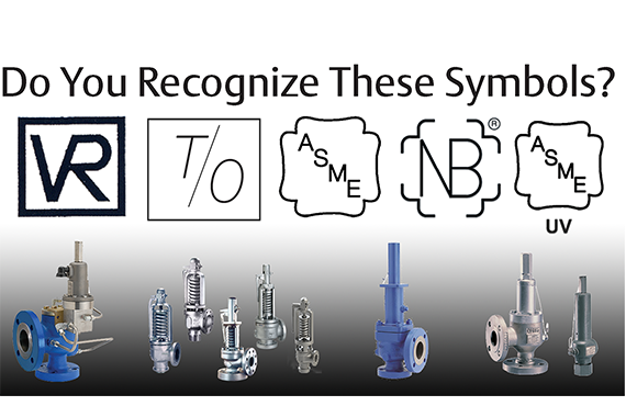
ASME I valve - A safety relief valve conforming to the requirements of Section I of the ASME pressure vessel code for boiler applications which will open within 3% overpressure and close within 4%. It will usually feature two blowdown rings, and is identified by a National Board ‘V’ stamp.
ASME VIII valve- A safety relief valve conforming to the requirements of Section VIII of the ASME pressure vessel code for pressure vessel applications which will open within 10% overpressure and close within 7%. Identified by a National Board ‘UV’ stamp.
Full bore safety valve - A safety valve having no protrusions in the bore, and wherein the valve lifts to an extent sufficient for the minimum area at any section, at or below the seat, to become the controlling orifice.
Conventional safety relief valve -The spring housing is vented to the discharge side, hence operational characteristics are directly affected by changes in the backpressure to the valve.
Balanced safety relief valve -A balanced valve incorporates a means of minimising the effect of backpressure on the operational characteristics of the valve.
Pilot operated pressure relief valve -The major relieving device is combined with, and is controlled by, a self-actuated auxiliary pressure relief device.
Power-actuated safety relief valve - A pressure relief valve in which the major pressure relieving device is combined with, and controlled by, a device requiring an external source of energy.
Standard safety valve - A valve which, following opening, reaches the degree of lift necessary for the mass flowrate to be discharged within a pressure rise of not more than 10%. (The valve is characterised by a pop type action and is sometimes known as high lift).
Full lift (Vollhub) safety valve -A safety valve which, after commencement of lift, opens rapidly within a 5% pressure rise up to the full lift as limited by the design. The amount of lift up to the rapid opening (proportional range) shall not be more than 20%.
Direct loaded safety valve -A safety valve in which the opening force underneath the valve disc is opposed by a closing force such as a spring or a weight.
Proportional safety valve - A safety valve which opens more or less steadily in relation to the increase in pressure. Sudden opening within a 10% lift range will not occur without pressure increase. Following opening within a pressure of not more than 10%, these safety valves achieve the lift necessary for the mass flow to be discharged.
Diaphragm safety valve -A direct loaded safety valve wherein linear moving and rotating elements and springs are protected against the effects of the fluid by a diaphragm
Bellows safety valve - A direct loaded safety valve wherein sliding and (partially or fully) rotating elements and springs are protected against the effects of the fluids by a bellows. The bellows may be of such a design that it compensates for influences of backpressure.
Controlled safety valve - Consists of a main valve and a control device. It also includes direct acting safety valves with supplementary loading in which, until the set pressure is reached, an additional force increases the closing force.
Safety valve - A safety valve which automatically, without the assistance of any energy other than that of the fluid concerned, discharges a quantity of the fluid so as to prevent a predetermined safe pressure being exceeded, and which is designed to re-close and prevent further flow of fluid after normal pressure conditions of service have been restored. Note; the valve can be characterised either by pop action (rapid opening) or by opening in proportion (not necessarily linear) to the increase in pressure over the set pressure.
Direct loaded safety valve -A safety valve in which the loading due to the fluid pressure underneath the valve disc is opposed only by a direct mechanical loading device such as a weight, lever and weight, or a spring.
Assisted safety valve -A safety valve which by means of a powered assistance mechanism, may additionally be lifted at a pressure lower than the set pressure and will, even in the event of a failure of the assistance mechanism, comply with all the requirements for safety valves given in the standard.
Supplementary loaded safety valve - A safety valve that has, until the pressure at the inlet to the safety valve reaches the set pressure, an additional force, which increases the sealing force.
Note; this additional force (supplementary load), which may be provided by means of an extraneous power source, is reliably released when the pressure at the inlet of the safety valve reaches the set pressure. The amount of supplementary loading is so arranged that if such supplementary loading is not released, the safety valve will attain its certified discharge capacity at a pressure not greater than 1.1 times the maximum allowable pressure of the equipment to be protected.
Pilot operated safety valve -A safety valve, the operation of which is initiated and controlled by the fluid discharged from a pilot valve, which is itself, a direct loaded safety valve subject to the requirement of the standard.
The common characteristic shared between the definitions of conventional safety valves in the different standards, is that their operational characteristics are affected by any backpressure in the discharge system. It is important to note that the total backpressure is generated from two components; superimposed backpressure and the built-up backpressure:
Subsequently, in a conventional safety valve, only the superimposed backpressure will affect the opening characteristic and set value, but the combined backpressure will alter the blowdown characteristic and re-seat value.
The ASME/ANSI standard makes the further classification that conventional valves have a spring housing that is vented to the discharge side of the valve. If the spring housing is vented to the atmosphere, any superimposed backpressure will still affect the operational characteristics. Thiscan be seen from Figure 9.2.1, which shows schematic diagrams of valves whose spring housings are vented to the discharge side of the valve and to the atmosphere.
By considering the forces acting on the disc (with area AD), it can be seen that the required opening force (equivalent to the product of inlet pressure (PV) and the nozzle area (AN)) is the sum of the spring force (FS) and the force due to the backpressure (PB) acting on the top and bottom of the disc. In the case of a spring housing vented to the discharge side of the valve (an ASME conventional safety relief valve, see Figure 9.2.1 (a)), the required opening force is:
In both cases, if a significant superimposed backpressure exists, its effects on the set pressure need to be considered when designing a safety valve system.
Once the valve starts to open, the effects of built-up backpressure also have to be taken into account. For a conventional safety valve with the spring housing vented to the discharge side of the valve, see Figure 9.2.1 (a), the effect of built-up backpressure can be determined by considering Equation 9.2.1 and by noting that once the valve starts to open, the inlet pressure is the sum of the set pressure, PS, and the overpressure, PO.
Balanced safety valves are those that incorporate a means of eliminating the effects of backpressure. There are two basic designs that can be used to achieve this:
Although there are several variations of the piston valve, they generally consist of a piston type disc whose movement is constrained by a vented guide. The area of the top face of the piston, AP, and the nozzle seat area, AN, are designed to be equal. This means that the effective area of both the top and bottom surfaces of the disc exposed to the backpressure are equal, and therefore any additional forces are balanced. In addition, the spring bonnet is vented such that the top face of the piston is subjected to atmospheric pressure, as shown in Figure 9.2.2.
The bellows arrangement prevents backpressure acting on the upper side of the disc within the area of the bellows. The disc area extending beyond the bellows and the opposing disc area are equal, and so the forces acting on the disc are balanced, and the backpressure has little effect on the valve opening pressure.
Bellows failure is an important concern when using a bellows balanced safety valve, as this may affect the set pressure and capacity of the valve. It is important, therefore, that there is some mechanism for detecting any uncharacteristic fluid flow through the bellows vents. In addition, some bellows balanced safety valves include an auxiliary piston that is used to overcome the effects of backpressure in the case of bellows failure. This type of safety valve is usually only used on critical applications in the oil and petrochemical industries.
Since balanced pressure relief valves are typically more expensive than their unbalanced counterparts, they are commonly only used where high pressure manifolds are unavoidable, or in critical applications where a very precise set pressure or blowdown is required.
This type of safety valve uses the flowing medium itself, through a pilot valve, to apply the closing force on the safety valve disc. The pilot valve is itself a small safety valve.
The diaphragm type is typically only available for low pressure applications and it produces a proportional type action, characteristic of relief valves used in liquid systems. They are therefore of little use in steam systems, consequently, they will not be considered in this text.
The piston type valve consists of a main valve, which uses a piston shaped closing device (or obturator), and an external pilot valve. Figure 9.2.4 shows a diagram of a typical piston type, pilot operated safety valve.
The piston and seating arrangement incorporated in the main valve is designed so that the bottom area of the piston, exposed to the inlet fluid, is less than the area of the top of the piston. As both ends of the piston are exposed to the fluid at the same pressure, this means that under normal system operating conditions, the closing force, resulting from the larger top area, is greater than the inlet force. The resultant downward force therefore holds the piston firmly on its seat.
If the inlet pressure were to rise, the net closing force on the piston also increases, ensuring that a tight shut-off is continually maintained. However, when the inlet pressure reaches the set pressure, the pilot valve will pop open to release the fluid pressure above the piston. With much less fluid pressure acting on the upper surface of the piston, the inlet pressure generates a net upwards force and the piston will leave its seat. This causes the main valve to pop open, allowing the process fluid to be discharged.
When the inlet pressure has been sufficiently reduced, the pilot valve will reclose, preventing the further release of fluid from the top of the piston, thereby re-establishing the net downward force, and causing the piston to reseat.
Pilot operated safety valves offer good overpressure and blowdown performance (a blowdown of 2% is attainable). For this reason, they are used where a narrow margin is required between the set pressure and the system operating pressure. Pilot operated valves are also available in much larger sizes, making them the preferred type of safety valve for larger capacities.
One of the main concerns with pilot operated safety valves is that the small bore, pilot connecting pipes are susceptible to blockage by foreign matter, or due to the collection of condensate in these pipes. This can lead to the failure of the valve, either in the open or closed position, depending on where the blockage occurs.
The terms full lift, high lift and low lift refer to the amount of travel the disc undergoes as it moves from its closed position to the position required to produce the certified discharge capacity, and how this affects the discharge capacity of the valve.
A full lift safety valve is one in which the disc lifts sufficiently, so that the curtain area no longer influences the discharge area. The discharge area, and therefore the capacity of the valve are subsequently determined by the bore area. This occurs when the disc lifts a distance of at least a quarter of the bore diameter. A full lift conventional safety valve is often the best choice for general steam applications.
The disc of a high lift safety valve lifts a distance of at least 1/12th of the bore diameter. This means that the curtain area, and ultimately the position of the disc, determines the discharge area. The discharge capacities of high lift valves tend to be significantly lower than those of full lift valves, and for a given discharge capacity, it is usually possible to select a full lift valve that has a nominal size several times smaller than a corresponding high lift valve, which usually incurs cost advantages.Furthermore, high lift valves tend to be used on compressible fluids where their action is more proportional.
In low lift valves, the disc only lifts a distance of 1/24th of the bore diameter. The discharge area is determined entirely by the position of the disc, and since the disc only lifts a small amount, the capacities tend to be much lower than those of full or high lift valves.
Except when safety valves are discharging, the only parts that are wetted by the process fluid are the inlet tract (nozzle) and the disc. Since safety valves operate infrequently under normal conditions, all other components can be manufactured from standard materials for most applications. There are however several exceptions, in which case, special materials have to be used, these include:
Cast steel -Commonly used on higher pressure valves (up to 40 bar g). Process type valves are usually made from a cast steel body with an austenitic full nozzle type construction.
For all safety valves, it is important that moving parts, particularly the spindle and guides are made from materials that will not easily degrade or corrode. As seats and discs are constantly in contact with the process fluid, they must be able to resist the effects of erosion and corrosion.
The spring is a critical element of the safety valve and must provide reliable performance within the required parameters. Standard safety valves will typically use carbon steel for moderate temperatures. Tungsten steel is used for higher temperature, non-corrosive applications, and stainless steel is used for corrosive or clean steam duty. For sour gas and high temperature applications, often special materials such as monel, hastelloy and ‘inconel’ are used.
Standard safety valves are generally fitted with an easing lever, which enables the valve to be lifted manually in order to ensure that it is operational at pressures in excess of 75% of set pressure. This is usually done as part of routine safety checks, or during maintenance to prevent seizing. The fitting of a lever is usually a requirement of national standards and insurance companies for steam and hot water applications. For example, the ASME Boiler and Pressure Vessel Code states that pressure relief valves must be fitted with a lever if they are to be used on air, water over 60°C, and steam.
A test gag (Figure 9.2.7) may be used to prevent the valve from opening at the set pressure during hydraulic testing when commissioning a system. Once tested, the gag screw is removed and replaced with a short blanking plug before the valve is placed in service.
The amount of fluid depends on the particular design of safety valve. If emission of this fluid into the atmosphere is acceptable, the spring housing may be vented to the atmosphere – an open bonnet. This is usually advantageous when the safety valve is used on high temperature fluids or for boiler applications as, otherwise, high temperatures can relax the spring, altering the set pressure of the valve. However, using an open bonnet exposes the valve spring and internals to environmental conditions, which can lead to damage and corrosion of the spring.
When the fluid must be completely contained by the safety valve (and the discharge system), it is necessary to use a closed bonnet, which is not vented to the atmosphere. This type of spring enclosure is almost universally used for small screwed valves and, it is becoming increasingly common on many valve ranges since, particularly on steam, discharge of the fluid could be hazardous to personnel.
Some safety valves, most commonly those used for water applications, incorporate a flexible diaphragm or bellows to isolate the safety valve spring and upper chamber from the process fluid, (see Figure 9.2.9).

As soon as mankind was able to boil water to create steam, the necessity of the safety device became evident. As long as 2000 years ago, the Chinese were using cauldrons with hinged lids to allow (relatively) safer production of steam. At the beginning of the 14th century, chemists used conical plugs and later, compressed springs to act as safety devices on pressurised vessels.
Early in the 19th century, boiler explosions on ships and locomotives frequently resulted from faulty safety devices, which led to the development of the first safety relief valves.
In 1848, Charles Retchie invented the accumulation chamber, which increases the compression surface within the safety valve allowing it to open rapidly within a narrow overpressure margin.
Today, most steam users are compelled by local health and safety regulations to ensure that their plant and processes incorporate safety devices and precautions, which ensure that dangerous conditions are prevented.
The principle type of device used to prevent overpressure in plant is the safety or safety relief valve. The safety valve operates by releasing a volume of fluid from within the plant when a predetermined maximum pressure is reached, thereby reducing the excess pressure in a safe manner. As the safety valve may be the only remaining device to prevent catastrophic failure under overpressure conditions, it is important that any such device is capable of operating at all times and under all possible conditions.
Safety valves should be installed wherever the maximum allowable working pressure (MAWP) of a system or pressure-containing vessel is likely to be exceeded. In steam systems, safety valves are typically used for boiler overpressure protection and other applications such as downstream of pressure reducing controls. Although their primary role is for safety, safety valves are also used in process operations to prevent product damage due to excess pressure. Pressure excess can be generated in a number of different situations, including:
The terms ‘safety valve’ and ‘safety relief valve’ are generic terms to describe many varieties of pressure relief devices that are designed to prevent excessive internal fluid pressure build-up. A wide range of different valves is available for many different applications and performance criteria.
In most national standards, specific definitions are given for the terms associated with safety and safety relief valves. There are several notable differences between the terminology used in the USA and Europe. One of the most important differences is that a valve referred to as a ‘safety valve’ in Europe is referred to as a ‘safety relief valve’ or ‘pressure relief valve’ in the USA. In addition, the term ‘safety valve’ in the USA generally refers specifically to the full-lift type of safety valve used in Europe.
Pressure relief valve- A spring-loaded pressure relief valve which is designed to open to relieve excess pressure and to reclose and prevent the further flow of fluid after normal conditions have been restored. It is characterised by a rapid-opening ‘pop’ action or by opening in a manner generally proportional to the increase in pressure over the opening pressure. It may be used for either compressible or incompressible fluids, depending on design, adjustment, or application.
Safety valves are primarily used with compressible gases and in particular for steam and air services. However, they can also be used for process type applications where they may be needed to protect the plant or to prevent spoilage of the product being processed.
Relief valve - A pressure relief device actuated by inlet static pressure having a gradual lift generally proportional to the increase in pressure over opening pressure.
Relief valves are commonly used in liquid systems, especially for lower capacities and thermal expansion duty. They can also be used on pumped systems as pressure overspill devices.
Safety relief valve - A pressure relief valve characterised by rapid opening or pop action, or by opening in proportion to the increase in pressure over the opening pressure, depending on the application, and which may be used either for liquid or compressible fluid.
In general, the safety relief valve will perform as a safety valve when used in a compressible gas system, but it will open in proportion to the overpressure when used in liquid systems, as would a relief valve.
Safety valve- A valve which automatically, without the assistance of any energy other than that of the fluid concerned, discharges a quantity of the fluid so as to prevent a predetermined safe pressure being exceeded, and which is designed to re-close and prevent further flow of fluid after normal pressure conditions of service have been restored.

Certifies Allied Valve Inc. is qualified and approved to assemble Pressure Relief Valves (PRV) for use in Section I applications including boilers and pressure vessels.
Certifies Allied Valve Inc. is qualified and approved to assemble Pressure Relief Valves (PRV) for use in Section VIII applications including all uses outside of boilers and pressure vessels.
Certifies Allied Valve Inc. is qualified and approved to calibrate, test, and stamp Pressure Relief Valves (PRV) for use in Section I and Section VIII applications.
Certifies Allied Valve Inc. is qualified and approved to repair Pressure Relief Valves (PRV) of all brands for both Section I and Section VIII applications.
The National Board offers the Certificate of Authorization and T/O mark for the inservice testing of pressure relief valves. Requirements are described in NB-528. Accreditation of T/o Test Only Organizations.

Years ago, it was not uncommon to read news about tragic boiler explosions, sometimes resulting in mass destruction. Today, boilers are equipped with important safety devises to help protect against these types of catastrophes. Let’s take a look at the most critical of these devices: the safety valve.
The safety valve is one of the most important safety devices in a steam system. Safety valves provide a measure of security for plant operators and equipment from over pressure conditions. The main function of a safety valve is to relieve pressure. It is located on the boiler steam drum, and will automatically open when the pressure of the inlet side of the valve increases past the preset pressure. All boilers are required by ASME code to have at least one safety valve, dependent upon the maximum flow capacity (MFC) of the boiler. The total capacity of the safety valve at the set point must exceed the steam control valve’s MFC if the steam valve were to fail to open. In most cases, two safety valves per boiler are required, and a third may be needed if they do not exceed the MFC.
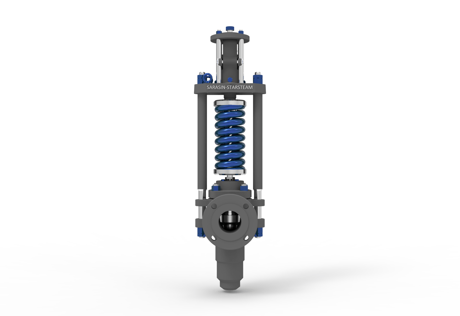
There are three main parts to the safety valve: nozzle, disc, and spring. Pressurized steam enters the valve through the nozzle and is then threaded to the boiler. The disc is the lid to the nozzle, which opens or closes depending on the pressure coming from the boiler. The spring is the pressure controller.
As a boiler starts to over pressure, the nozzle will start to receive a higher pressure coming from the inlet side of the valve, and will start to sound like it is simmering. When the pressure becomes higher than the predetermined pressure of the spring, the disc will start to lift and release the steam, creating a “pop” sound. After it has released and the steam and pressure drops below the set pressure of the valve, the spring will close the disc. Once the safety valve has popped, it is important to check the valve to make sure it is not damaged and is working properly.
A safety valve is usually referred to as the last line of safety defense. Without safety valves, the boiler can exceed it’s maximum allowable working pressure (MAWP) and not only damage equipment, but also injure or kill plant operators that are close by. Many variables can cause a safety valve on a boiler to lift, such as a compressed air or electrical power failure to control instrumentation, or an imbalance of feedwater rate caused by an inadvertently shut or open isolation valve.
Once a safety valve has lifted, it is important to do a complete boiler inspection and confirm that there are no other boiler servicing issues. A safety valve should only do its job once; safety valves should not lift continuously. Lastly, it is important to have the safety valves fully repaired, cleaned and recertified with a National Board valve repair (VR) stamp as required by local code or jurisdiction. Safety valves are a critical component in a steam system, and must be maintained.
All of Nationwide Boiler’s rental boilers include on to two safety valves depending on the size; one set at design pressure and the other set slightly higher than design. By request, we can reset the safeties to a lower pressure if the application requires it. In addition, the valves are thoroughly checked after every rental and before going out to a new customer, and they are replaced and re-certified as needed.
Safety valves play an important role in keeping people and equipment safe. Building on the long legacy of the Consolidated Safety Valves, we work closely with customers and regulatory organizations to configure, engineer, and manufacture safety valves that can help maintain safer operating conditions in a full range of environments.
Our safety valves comply with the ASME Section I code for boiler applications. They are built with many features that meet ASME requirements for steam-compressible fluids. Baker Hughes’s Consolidated safety valves are known for exceptional quality, performance and dependability. It is important they are reliable even the in most demanding real-world applications. With a range of styles, models, options and configurations, our safety valves work in many different applications.
Not sure which valve you need for your application?Download ValSpeQ (Mooney regulators & Becker valves) or ValvStream™ (Masoneilan and Consolidated valves) to size, select and generate proposal documentation for your valves.
Consolidated Green Tag Centers (GTC) comprise one of the broadest OEM service networks in the industry. With more than 80 facilities located in more than 30 countries worldwide, the GTCNet™ network provides the aftermarket support you need. Our GTC customers receive responsive and effective service through OEM-certified repairs, innovative valve diagnostics from ValvKeep™- valve management and maintenance software, and the EVT-Pro, an electronic valve testing device. Each GTC location is staffed with highly qualified technicians, specifically trained and certified to deliver exceptional product support and technical expertise.
Pressure relief devices are used to provide a means of venting excess pressure which could rupture a boiler or pressure vessel. A pressure relief device is the last line of defense for safety. If all other safety devices or operating controls fail, the pressure relief device must be capable of venting excess pressure.
There are many types of pressure relief devices available for use in the boiler and pressure vessel industry. This inspector guide will address the most common devices found on boilers and pressure vessels. Virtually all jurisdictions require a pressure relief device to be manufactured and certified in accordance with the ASME BPV Code in addition to being capacity-certified by the National Board.
Safety Valve – This device is typically used for steam or vapor service. It operates automatically with a full-opening pop action and recloses when the pressure drops to a value consistent with the blowdown requirements prescribed by the applicable governing code or standard.
Relief Valve – This device is typically used for liquid service. It operates automatically by opening farther as the pressure increases beyond the initial opening pressure and recloses when the pressure drops below the opening pressure.
Safety Relief Valve – This device includes the operating characteristics of both a safety valve and a relief valve and may be used in either application.
Temperature and Pressure Safety Relief Valve – This device is typically used on potable water heaters. In addition to its pressure-relief function, it also includes a temperature-sensing element which causes the device to open at a predetermined temperature regardless of pressure. The set temperature on these devices is usually 210°F.
Some devices, especially on larger boilers, may have a discharge pipe arrangement which incorporates provisions for expansion as the boiler heats up or cools down. These expansion provisions must allow the full range of movement required to prevent loads being applied to the device body.
Drain holes in the device body and discharge piping, when applicable, must be open to allow drainage of liquids from over the device disk on spring loaded valves. Any liquid allowed to remain on top of the device disk can adversely affect the operating characteristics of the device.
Most jurisdictional requirements state the device must be "piped to a point of safe discharge." This must be accomplished while keeping the run of discharge piping as short as possible. Most jurisdictions also limit the number of 90 degree elbows that may be installed in the discharge piping. Too long of a run and multiple elbows can adversely affect the operation of the device.
While inspecting a boiler or pressure vessel, the inspector will also be evaluating the pressure relief device(s) installed on, or associated with, the equipment. The inspector should:
Compare the device nameplate set pressure with the boiler or pressure vessel maximum allowable working pressure (MAWP) and ensure the device set pressure does not exceed the MAWP. A device with a set pressure less than MAWP is acceptable. If multiple devices are used, at least one must have a set pressure equal to or less than the MAWP. The ASME Code should be reviewed for other conditions relating to the use of multiple devices.
Instruct the owner or owner"s representative to lift the test lever, if so equipped, on spring-loaded devices. ASME BPV Code Section IV devices can have the test levers lifted without pressure in the boiler. All other devices must have at least 75% of the device set pressure under the device disk prior to lifting the test lever. If the device is found to be stuck in a closed position, the equipment should be immediately removed from service until such time the device can be replaced or repaired.
Additional information to aid inspections of pressure relief devices, including installation requirements, can be found in the following publications and sources:

Tired of keeping track of your valve inventory’s annual certification records? We offer complete management of your safety relief valves. With an inventory of repair parts and in stock relief valves of all sizes, we can respond to any customer emergency. We offer annual certification services as well as repair of all major brands, including Kunkle, Conbraco, Consolidated, Dresser, Apollo and more.
A specially engineered internal design provides the fast response overpressure and blowdown requirements which are demanded by ASME BPVC Section I code of practice
Thermoglide design improves the gliding characteristics of internal parts thus enabling the valve to achieve its full lift and re-seat point within the fastest possible time

Safety valves are used in a variety of industrial applications to include air/gas, vapor, steam, and liquid service, among many more. These pressure relief valves are critical to the safe operation of our customer’s equipment and provide—as their name implies—a safety measure that can reduce the number of risks that can threaten both your personnel and facilities.
Millennium Power Services’ safety valve technicians will get your valves tested, repaired, and quickly set to the exact specifications. We serve as your knowledge partner and will also evaluate the repair condition of every valve and make recommendations as needed to help you make the best decisions.

A relief valve is one of the most crucial pressured system components and often the last device to prevent catastrophic failures in high-pressured systems. That is why it is essential that relief valves are always certified and should work at all times.
Relief valves are pressure valves that are designed to open at a preset pressure and discharge fluid until the pressure drops to a safe and acceptable level. This means the relief valve is the last resort that releases pressure when other components in the system have failed to control the pressure.
Safety is of paramount importance when it comes to dealing with relief valves. So, it’s critical for industries to make sure the valves are working as designed.
The only way to do that is through periodic inspection and standardized testing. The standards about relief valves and associated assemblies like boilers and pressured vessels are regulated by ASME, API, OSHA, National Board, and individual State codes.
Standard requirements include periodic inspection, testing, and recertification. Certification assures that a valve’s condition and performance are essentially equal to that of a new valve.
Though ASME is the leading organization governing pressured systems’ standards and codes, the body itself does not certify the valves. Certification and recertification of relief valves are done by the National Board (NB).
Performing periodic testing on relief valves is the best practice to ensure that the valves are in good working condition and the employees and work environment is safe.
The above recommendations constitute correct inspecting and testing practices for efficient Relief Valve operations and, ultimately, a safe working environment. However, one crucial safety measure is to use a pressure indicator with a full-scale range higher than the valve’s relief pressure.
In fact, we believe proper valve inspection, testing, and maintenance is the best investment you make in the safety and security of your company and employees.
Our valve experts focus on getting your old valves tested and recertified for safe use. On top of that, we evaluate the repair condition of every valve and recommend the right solution to manage your equipment better.

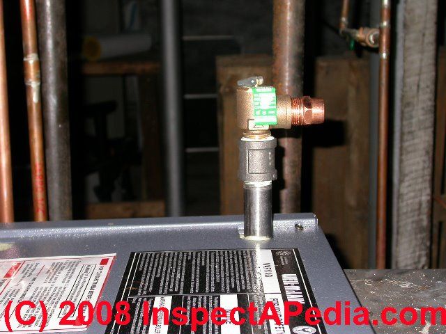
A series of anomalies occurred in the boiler room that evening. The steel compression tank for the hydronic loop flooded, leaving no room for expansion. Water will expand at 3% of its volume when heated from room temperature to 180° F. When the burner fired, the expansion of the water increased the system pressure within the boiler. The malfunctioning operating control did not shut off the burner at the set point which caused the relief valve to open.
The brass relief valve discharge was installed with copper tubing piped solid to a 90° ell on the floor and the tubing further extended to the floor drain. The combination of hot water and steam from the boiler caused the discharge copper tubing to expand, using the relief valve as a fulcrum. The expansion of the copper discharge tubing pressing against the floor was enough to crack the brass relief valve, flooding the boiler room. The damage was not discovered until the next morning, several hours after the leak occurred. Thousands of dollars in damage was sustained and luckily no one was injured.
Each boiler requires some sort of pressure relieving device. They are referred to as either a safety, relief or safety relief valve. While these names are often thought of as interchangeable, there are subtle differences between them. According to the National Board of Boiler and Pressure Vessel Inspectors, the following are the definitions of each:
• Safety valve— This device is typically used for steam or vapor service. It operates automatically with a full-opening pop action and recloses when the pressure drops to a value consistent with the blowdown requirements prescribed by the applicable governing code or standard.
• Relief valve— This device is used for liquid service. It operates automatically by opening farther as the pressure increases beyond the initial opening pressure and recloses when the pressure drops below the opening pressure.
• Safety relief valve— This device includes the operating characteristics of both a safety valve and a relief valve and may be used in either application.
• Temperature and pressure safety relief valve— This device is typically used on potable water heaters. In addition to its pressure-relief function, it also includes a temperature-sensing element which causes the device to open at a predetermined temperature regardless of pressure. The set temperature on these devices is usually 210°.
• Relief valve piping— The boiler contractor installed a bushing on the outlet of the safety relief valve. Instead of 1 1/2-in. pipe, the installer used 3/4-in. pipe. When asked about it, he answered that he did not have any 1 1/2-in. pipe but had plenty of 3/4-in. pipe. I explained and then had to show the disbelieving contractor the code that states that the relief valve discharge piping has to be the same diameter as the relief valve outlet (see 2012 International Mechanical Code, 1006.6). By reducing the discharge pipe size, the relieving capacity of the safety valve may not be adequate to properly relieve the pressure inside the boiler, causing a dangerous situation.
The code also states that the discharge material shall be of rigid pipe that is approved for the temperature of the system. The inlet pipe size shall be full diameter of the pipe inlet for the relief valve. Some manufacturers suggest using black iron pipe rather than copper tubing. If using copper, it should have an air space that allows expansion should the relief valve open to avoid the accident that I referenced above. The discharge piping has to be supported and the weight of the piping should not be on the safety relief valve. Valves are not permitted in the inlet piping to or discharge piping from the relief valve. If you are using copper tubing on discharge piping, verify that there is room for expansion.
• Installation— Read the manufacturer’s installation manual as each may have different requirements. For instance, Conbraco requires that the discharge piping must terminate with a plain end and use a material that can handle temperatures of 375° or greater. This will preclude PVC or CPVC pipe for the discharge piping. The instruction manual for its model 12-14 steam relief valve stipulates that you cannot use a pipe wrench to install it. That would be good to know.
I once visited Boiler Utopia as the floor was clean and waxed. All the pipes were covered and exposed pipes were painted. There were large stickers detailing what was inside each pipe as well as directional arrows. Nothing was stacked next to the boilers. Yellow caution lines were painted on the floor around each boiler. I was in heaven. As I walked around the rear of the boiler, something clicked and triggered a warning bell. The discharge of the relief valve piping was about 6 in. from the floor but instead of a plain or angled cut end, the pipe had a threaded pipe cap on the termination. I asked the maintenance person about it and he said that the valve was leaking all over his newly waxed floor and this was the only way he could stop it. When I said that the discharge pipe should not have been threaded, he explained that it was not threaded and he had to take it to the local hardware store to thread it. I informed him that the cap had to be removed. We cut the pipe on an angle to prevent this.
• Steam boiler— Most manufacturers recommend a drip pan ell on the discharge of the steam boiler relief valve to eliminate the weight of the discharge piping on the relief valve. Some codes require the discharge to be vented outdoors.
• Testing— I will ask the attendees in my classes, “How often do you test the relief valves?” Most do not make eye contact and when I follow up with, “Why are they not tested?” I often hear that opening the relief valve will cause it to leak. I suggest that you refer to each manufacturer’s directions for testing. For instance, one will recommend once a year while another recommends twice a year. One manufacturer says, “Safety/relief valves should be operated only often enough to assure they are in good working order.” I am not sure what that even means. You want to also verify the proper test procedure as some will only want the relief valve tested when the boiler is at 75% of the rated pressure or higher of the relief valve.

H. When two or more boilers, operating at different pressures and safety valve settings, are interconnected, the lower pressure boilers or interconnected piping shall have safety valves of sufficient capacity to prevent over-pressure, considering the maximum generating capacity of all boilers.
I. A boiler supplied with feedwater directly from a water main without the use of feeding apparatus other than a return trap, may not have a safety valve set at a pressure greater than 94 percent of the lowest pressure obtained in the supply main feeding the boiler.
(a) An accumulation test (unless the valve is located on a boiler having a superheater or reheater), performed by shutting off all other steam-discharge outlets from the boiler and forcing fires to the maximum. The safety valve relief capacity shall be sufficient to prevent increased pressure in excess of 6 percent of the maximum allowable working pressure.
(2) When either method in §J(1)(b) or (c) is used, the sum of the safety valve capacities shall equal or exceed the maximum evaporative capacity of the boiler.

A little product education can make you look super smart to customers, which usually means more orders for everything you sell. Here’s a few things to keep in mind about safety valves, so your customers will think you’re a genius.
A safety valve is required on anything that has pressure on it. It can be a boiler (high- or low-pressure), a compressor, heat exchanger, economizer, any pressure vessel, deaerator tank, sterilizer, after a reducing valve, etc.
There are four main types of safety valves: conventional, bellows, pilot-operated, and temperature and pressure. For this column, we will deal with conventional valves.
A safety valve is a simple but delicate device. It’s just two pieces of metal squeezed together by a spring. It is passive because it just sits there waiting for system pressure to rise. If everything else in the system works correctly, then the safety valve will never go off.
A safety valve is NOT 100% tight up to the set pressure. This is VERY important. A safety valve functions a little like a tea kettle. As the temperature rises in the kettle, it starts to hiss and spit when the water is almost at a boil. A safety valve functions the same way but with pressure not temperature. The set pressure must be at least 10% above the operating pressure or 5 psig, whichever is greater. So, if a system is operating at 25 psig, then the minimum set pressure of the safety valve would be 30 psig.
Most valve manufacturers prefer a 10 psig differential just so the customer has fewer problems. If a valve is positioned after a reducing valve, find out the max pressure that the equipment downstream can handle. If it can handle 40 psig, then set the valve at 40. If the customer is operating at 100 psig, then 110 would be the minimum. If the max pressure in this case is 150, then set it at 150. The equipment is still protected and they won’t have as many problems with the safety valve.
Here’s another reason the safety valve is set higher than the operating pressure: When it relieves, it needs room to shut off. This is called BLOWDOWN. In a steam and air valve there is at least one if not two adjusting rings to help control blowdown. They are adjusted to shut the valve off when the pressure subsides to 6% below the set pressure. There are variations to 6% but for our purposes it is good enough. So, if you operate a boiler at 100 psig and you set the safety valve at 105, it will probably leak. But if it didn’t, the blowdown would be set at 99, and the valve would never shut off because the operating pressure would be greater than the blowdown.
All safety valves that are on steam or air are required by code to have a test lever. It can be a plain open lever or a completely enclosed packed lever.
Safety valves are sized by flow rate not by pipe size. If a customer wants a 12″ safety valve, ask them the flow rate and the pressure setting. It will probably turn out that they need an 8×10 instead of a 12×16. Safety valves are not like gate valves. If you have a 12″ line, you put in a 12″ gate valve. If safety valves are sized too large, they will not function correctly. They will chatter and beat themselves to death.
Safety valves need to be selected for the worst possible scenario. If you are sizing a pressure reducing station that has 150 psig steam being reduced to 10 psig, you need a safety valve that is rated for 150 psig even though it is set at 15. You can’t put a 15 psig low-pressure boiler valve after the reducing valve because the body of the valve must to be able to handle the 150 psig of steam in case the reducing valve fails.
The seating surface in a safety valve is surprisingly small. In a 3×4 valve, the seating surface is 1/8″ wide and 5″ around. All it takes is one pop with a piece of debris going through and it can leak. Here’s an example: Folgers had a plant in downtown Kansas City that had a 6×8 DISCONTINUED Consolidated 1411Q set at 15 psig. The valve was probably 70 years old. We repaired it, but it leaked when plant maintenance put it back on. It was after a reducing valve, and I asked him if he played with the reducing valve and brought the pressure up to pop the safety valve. He said no, but I didn’t believe him. I told him the valve didn’t leak when it left our shop and to send it back.
If there is a problem with a safety valve, 99% of the time it is not the safety valve or the company that set it. There may be other reasons that the pressure is rising in the system before the safety valve. Some ethanol plants have a problem on starting up their boilers. The valves are set at 150 and they operate at 120 but at startup the pressure gets away from them and there is a spike, which creates enough pressure to cause a leak until things get under control.
If your customer is complaining that the valve is leaking, ask questions before a replacement is sent out. What is the operating pressure below the safety valve? If it is too close to the set pressure then they have to lower their operating pressure or raise the set pressure on the safety valve.
Is the valve installed in a vertical position? If it is on a 45-degree angle, horizontal, or upside down then it needs to be corrected. I have heard of two valves that were upside down in my 47 years. One was on a steam tractor and the other one was on a high-pressure compressor station in the New Mexico desert. He bought a 1/4″ valve set at 5,000 psig. On the outlet side, he left the end cap in the outlet and put a pin hole in it so he could hear if it was leaking or not. He hit the switch and when it got up to 3,500 psig the end cap came flying out like a missile past his nose. I told him to turn that sucker in the right direction and he shouldn’t have any problems. I never heard from him so I guess it worked.
If the set pressure is correct, and the valve is vertical, ask if the outlet piping is supported by something other than the safety valve. If they don’t have pipe hangers or a wall or something to keep the stress off the safety valve, it will leak.
There was a plant in Springfield, Mo. that couldn’t start up because a 2″ valve was leaking on a tank. It was set at 750 psig, and the factory replaced it 5 times. We are not going to replace any valves until certain questions are answered. I was called to solve the problem. The operating pressure was 450 so that wasn’t the problem. It was in a vertical position so we moved on to the piping. You could tell the guy was on his cell phone when I asked if there was any piping on the outlet. He said while looking at the installation that he had a 2″ line coming out into a 2×3 connection going up a story into a 3×4 connection and going up another story. I asked him if there was any support for this mess, and he hung up the phone. He didn’t say thank you, goodbye, or send me a Christmas present.

A deaerator requires a source of heat in the form of steam to heat the feedwater to saturation and to remove dissolved gases. For many deaerators, this source of steam is high-pressure steam reduced to the desired deaerator operating pressure by a steam pressure control valve.
In the event of a steam pressure control valve failure, an excess flow of steam will be provided to the deaerator, causing the deaerator pressure to rise. In the worst conceivable case, the maximum excess steam flow may be considered to be the steam flow which the pressure reducing valve can pass with the usual supply pressure on its upstream side and deaerator design pressure on its downstream side. This assumes that the valve has failed in the wide open position and that the deaerator load is zero (i.e., the deaerator has a zero steam demand).
The wide open capacity of pressure control valves can be obtained with the valve manufacturer"s assistance or can be calculated from data in the form of maximum flow coefficients for the valve(s) installed in the system.
In some plants, this HP condensate is drained to a receiver where its pressure and temperature is reduced to atmospheric conditions (0 gauge pressure, 212°F or less). Pumps are then used to transfer the "flashed" condensate to the deaerator. Under these conditions, the HP condensate does not present a risk of overpressurizing the deaerator. However, in many situations where it is desired to conserve heat, HP process condensates may be returned directly to the deaerator. In these cases, the excess heat in the condensate must be absorbed by colder streams (e.g., makeup water and cool condensates) entering the deaerator if the deaerator pressure is to be controlled at a steady level. Heat not absorbed goes into elevating the operating temperature and pressure within the deaerator. If the condensate can produce a positive amount of flash steam when reduced to the deaerator design pressure, that amount of flash steam should be included in the safety valve capacity requirement.
Safety valve capacity required to protect against overpressure due to excessive continuous blowoff may be determined by calculating the amount of flash steam produced when the maximum blowoff flow is flashed to a pressure equal to the design pressure of the deaerator and that amount of flash steam should be included in the safety valve capacity requirement. The maximum blowoff flow to be considered is a function of boiler pressure, the number, size, and setting of the blowoff valves as well as the blowoff line size.
In some installations, the steam supply to the deaerator may consist of steam turbine exhaust, augmented with reduced high-pressure steam (described above). If the maximum turbine exhaust pressure exceeds the deaerator design pressure, safety valves must be provided to protect the deaerator; otherwise, relief or safety valves will be needed to protect the turbine. Since the worst case for excessive turbine exhaust flow would occur at zero deaerator load, the safety valve capacity needed to protect against overpressure due to a turbine exhaust is equal to the throttle flow of all turbine(s) connected to the deaerator steam line. Maximum throttle flow information can be obtained from the turbine manufacturer.
If the pressure of any feedstream to the deaerator exceeds, or may exceed, deaerator design pressure, adequate relieving capacity must be provided to protect the unit against overpressure from that source. Consideration should be given to the shutoff heads of feedpumps and water supply pressures as well as to the steam sources described above. Usually, the safety valves required for liquid relief alone would be considerably smaller in size than those required for steam relief.
Usually, the deaerator manufacturer will not provide full capacity safety valves with his equipment. When specified to be within this scope of supply, the deaerator manufacturer can size and supply the required safety valves only when the user or plant designer has supplied all needed details related to sources of overpressure in his system. In the absence of complete information, the deaerator supplier may furnish relief valves in accordance with the HEI Standards For Deaerators. The safety valve number and sizes recommended by the HEI standards are determined on an arbitrary basis and are intended to protect the deaerator against overpressure due to minor sources of overpressure, such as the introduction of excess amounts of HP condensate. However, the HEI-recommended safety valve sizes should be considered as minimums and to ensure a compliant installation, their adequacy for any application should be verified.
The ASME Code requires that sufficient relief valve capacity be provided to prevent the pressure inside the deaerator and storage tank from rising more than 10% or 3 psi, whichever is greater, above the maximum allowable working pressure of the vessels when a single safety valve or relieving device is utilized. When multiple safety valves are utilized, the set pressures of the individual devices may be staggered as permitted in paragraph UG-134 of the code. Safety valves on deaerators are normally set to relieve at maximum allowable working pressure of the vessels.
Safety valves for use on ASME Code vessels must meet the manufacturing and certification requirements set by the Code and outlined in Paragraphs UG-125 through UG-136 of ASME Section VIII, Division 1.
The ASME Code requires that safety valves intended for relieving steam be connected to the steam space of the pressure vessel when the source of overpressure is internal to the vessel. For this reason, it is common to connect the safety valves to protect against overpressure due to excessive flashing returns directly on the deaerator. If the source of overpressure is external to the pressure vessel, the ASME Code does not require the safety valves to be installed directly on the vessel. It is for this reason that the full capacity safety valves, whether provided by the


 8613371530291