
boiler safety valve requirements for sale

Boiler explosions have been responsible for widespread damage to companies throughout the years, and that’s why today’s boilers are equipped with safety valves and/or relief valves. Boiler safety valves are designed to prevent excess pressure, which is usually responsible for those devastating explosions. That said, to ensure that boiler safety valves are working properly and providing adequate protection, they must meet regulatory specifications and require ongoing maintenance and periodic testing. Without these precautions, malfunctioning safety valves may fail, resulting in potentially disastrous consequences.
Boiler safety valves are activated by upstream pressure. If the pressure exceeds a defined threshold, the valve activates and automatically releases pressure. Typically used for gas or vapor service, boiler safety valves pop fully open once a pressure threshold is reached and remain open until the boiler pressure reaches a pre-defined, safe lower pressure.
Boiler relief valves serve the same purpose – automatically lowering boiler pressure – but they function a bit differently than safety valves. A relief valve doesn’t open fully when pressure exceeds a defined threshold; instead, it opens gradually when the pressure threshold is exceeded and closes gradually until the lower, safe threshold is reached. Boiler relief valves are typically used for liquid service.
There are also devices known as “safety relief valves” which have the characteristics of both types discussed above. Safety relief valves can be used for either liquid or gas or vapor service.
Nameplates must be fastened securely and permanently to the safety valve and remain readable throughout the lifespan of the valve, so durability is key.
The National Board of Boiler and Pressure Vessel Inspectors offers guidance and recommendations on boiler and pressure vessel safety rules and regulations. However, most individual states set forth their own rules and regulations, and while they may be similar across states, it’s important to ensure that your boiler safety valves meet all state and local regulatory requirements.
The National Board published NB-131, Recommended Boiler and Pressure Vessel Safety Legislation, and NB-132, Recommended Administrative Boiler and Pressure Vessel Safety Rules and Regulationsin order to provide guidance and encourage the development of crucial safety laws in jurisdictions that currently have no laws in place for the “proper construction, installation, inspection, operation, maintenance, alterations, and repairs” necessary to protect workers and the public from dangerous boiler and pressure vessel explosions that may occur without these safeguards in place.
The documents are meant to be used as a guide for developing local laws and regulations and also may be used to update a jurisdiction’s existing requirements. As such, they’re intended to be modifiable to meet any jurisdiction’s local conditions.
The American Society of Mechanical Engineers (ASME) governs the code that establishes guidelines and requirements for safety valves. Note that it’s up to plant personnel to familiarize themselves with the requirements and understand which parts of the code apply to specific parts of the plant’s steam systems.
High steam capacity requirements, physical or economic constraints may make the use of a single safety valve impossible. In these cases, using multiple safety valves on the same system is considered an acceptable practice, provided that proper sizing and installation requirements are met – including an appropriately sized vent pipe that accounts for the total steam venting capacity of all valves when open at the same time.
The lowest rating (MAWP or maximum allowable working pressure) should always be used among all safety devices within a system, including boilers, pressure vessels, and equipment piping systems, to determine the safety valve set pressure.
Avoid isolating safety valves from the system, such as by installing intervening shut-off valves located between the steam component or system and the inlet.
Contact the valve supplier immediately for any safety valve with a broken wire seal, as this indicates that the valve is unsafe for use. Safety valves are sealed and certified in order to prevent tampering that can prevent proper function.
Avoid attaching vent discharge piping directly to a safety valve, which may place unnecessary weight and additional stress on the valve, altering the set pressure.

Choose these valves for small steam-heating boilers requiring pressure relief between 5 psi and 12 psi. They spring fully open at the set pressure and remain open until the system pressure is restored below the set pressure. All have a bronze body for durability and a long service life.

Choose these valves for small steam-heating boilers requiring pressure relief between 5 psi and 12 psi. They spring fully open at the set pressure and remain open until the system pressure is restored below the set pressure. All have a bronze body for durability and a long service life.

After a boiler has been engineered, built and tested for a given operating pressure there is only one reliable way to prevent operation of the boiler above this design pressure. This is a safety valve. The safety valve should be sized so that a single valve can handle the maximum steam production rate of the boiler and once open prevent boiler pressure to continue to rise. Standard operating procedure for the last century has been to install two safety valves on the boiler, one set 3-5 lbs below the design pressure and one valve set at the design pressure.
The 1st valve listed below is a true adjustable differential pop valve. The differential is adjured through the differential rings lock screw hole, from 3 PSI to whatever the operator desires. The pressure of the valve can be adjusted from 40 to 200 PSI.
The other valves listed are adjustable for release pressure and have a "pop" action: The pressure differential is not adjustable on these valves. If the valves are operated above their nominal pressure, the set-reset differential increases. If operated at lower pressure, the differential decreases to the point of disappearing about 10-15% below nominal pressure.
Years ago, it was not uncommon to read news about tragic boiler explosions, sometimes resulting in mass destruction. Today, boilers are equipped with important safety devises to help protect against these types of catastrophes. Let’s take a look at the most critical of these devices: the safety valve.
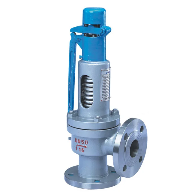
The safety valve is one of the most important safety devices in a steam system. Safety valves provide a measure of security for plant operators and equipment from over pressure conditions. The main function of a safety valve is to relieve pressure. It is located on the boiler steam drum, and will automatically open when the pressure of the inlet side of the valve increases past the preset pressure. All boilers are required by ASME code to have at least one safety valve, dependent upon the maximum flow capacity (MFC) of the boiler. The total capacity of the safety valve at the set point must exceed the steam control valve’s MFC if the steam valve were to fail to open. In most cases, two safety valves per boiler are required, and a third may be needed if they do not exceed the MFC.
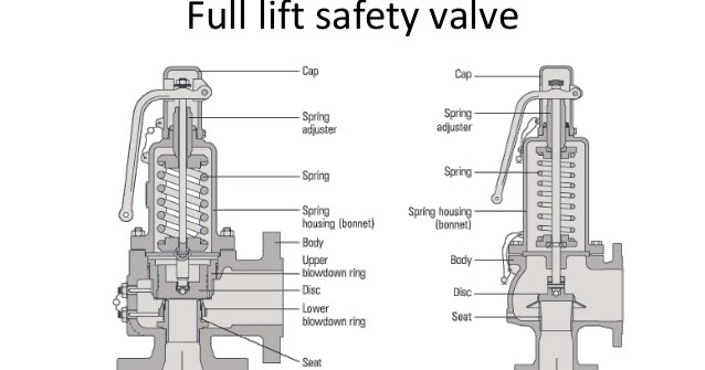
There are three main parts to the safety valve: nozzle, disc, and spring. Pressurized steam enters the valve through the nozzle and is then threaded to the boiler. The disc is the lid to the nozzle, which opens or closes depending on the pressure coming from the boiler. The spring is the pressure controller.
As a boiler starts to over pressure, the nozzle will start to receive a higher pressure coming from the inlet side of the valve, and will start to sound like it is simmering. When the pressure becomes higher than the predetermined pressure of the spring, the disc will start to lift and release the steam, creating a “pop” sound. After it has released and the steam and pressure drops below the set pressure of the valve, the spring will close the disc. Once the safety valve has popped, it is important to check the valve to make sure it is not damaged and is working properly.
A safety valve is usually referred to as the last line of safety defense. Without safety valves, the boiler can exceed it’s maximum allowable working pressure (MAWP) and not only damage equipment, but also injure or kill plant operators that are close by. Many variables can cause a safety valve on a boiler to lift, such as a compressed air or electrical power failure to control instrumentation, or an imbalance of feedwater rate caused by an inadvertently shut or open isolation valve.
Once a safety valve has lifted, it is important to do a complete boiler inspection and confirm that there are no other boiler servicing issues. A safety valve should only do its job once; safety valves should not lift continuously. Lastly, it is important to have the safety valves fully repaired, cleaned and recertified with a National Board valve repair (VR) stamp as required by local code or jurisdiction. Safety valves are a critical component in a steam system, and must be maintained.
All of Nationwide Boiler’s rental boilers include on to two safety valves depending on the size; one set at design pressure and the other set slightly higher than design. By request, we can reset the safeties to a lower pressure if the application requires it. In addition, the valves are thoroughly checked after every rental and before going out to a new customer, and they are replaced and re-certified as needed.

(a) The relief valve requirements for hot water boilers must be as indicated in article 4 of section IV of the ASME Boiler and Pressure Vessel Code (incorporated by reference; see 46 CFR 53.01-1) except as noted otherwise in this section.
(c) Hot water supply boilers. Each hot water supply boiler must have at least one safety relief valve and a temperature relief valve or a pressure-temperature relief valve. The valve temperature setting must not be more than 99 °C (210 °F).
A little product education can make you look super smart to customers, which usually means more orders for everything you sell. Here’s a few things to keep in mind about safety valves, so your customers will think you’re a genius.
A safety valve is required on anything that has pressure on it. It can be a boiler (high- or low-pressure), a compressor, heat exchanger, economizer, any pressure vessel, deaerator tank, sterilizer, after a reducing valve, etc.
There are four main types of safety valves: conventional, bellows, pilot-operated, and temperature and pressure. For this column, we will deal with conventional valves.
A safety valve is a simple but delicate device. It’s just two pieces of metal squeezed together by a spring. It is passive because it just sits there waiting for system pressure to rise. If everything else in the system works correctly, then the safety valve will never go off.
A safety valve is NOT 100% tight up to the set pressure. This is VERY important. A safety valve functions a little like a tea kettle. As the temperature rises in the kettle, it starts to hiss and spit when the water is almost at a boil. A safety valve functions the same way but with pressure not temperature. The set pressure must be at least 10% above the operating pressure or 5 psig, whichever is greater. So, if a system is operating at 25 psig, then the minimum set pressure of the safety valve would be 30 psig.
Most valve manufacturers prefer a 10 psig differential just so the customer has fewer problems. If a valve is positioned after a reducing valve, find out the max pressure that the equipment downstream can handle. If it can handle 40 psig, then set the valve at 40. If the customer is operating at 100 psig, then 110 would be the minimum. If the max pressure in this case is 150, then set it at 150. The equipment is still protected and they won’t have as many problems with the safety valve.
Here’s another reason the safety valve is set higher than the operating pressure: When it relieves, it needs room to shut off. This is called BLOWDOWN. In a steam and air valve there is at least one if not two adjusting rings to help control blowdown. They are adjusted to shut the valve off when the pressure subsides to 6% below the set pressure. There are variations to 6% but for our purposes it is good enough. So, if you operate a boiler at 100 psig and you set the safety valve at 105, it will probably leak. But if it didn’t, the blowdown would be set at 99, and the valve would never shut off because the operating pressure would be greater than the blowdown.
All safety valves that are on steam or air are required by code to have a test lever. It can be a plain open lever or a completely enclosed packed lever.
Safety valves are sized by flow rate not by pipe size. If a customer wants a 12″ safety valve, ask them the flow rate and the pressure setting. It will probably turn out that they need an 8×10 instead of a 12×16. Safety valves are not like gate valves. If you have a 12″ line, you put in a 12″ gate valve. If safety valves are sized too large, they will not function correctly. They will chatter and beat themselves to death.
Safety valves need to be selected for the worst possible scenario. If you are sizing a pressure reducing station that has 150 psig steam being reduced to 10 psig, you need a safety valve that is rated for 150 psig even though it is set at 15. You can’t put a 15 psig low-pressure boiler valve after the reducing valve because the body of the valve must to be able to handle the 150 psig of steam in case the reducing valve fails.
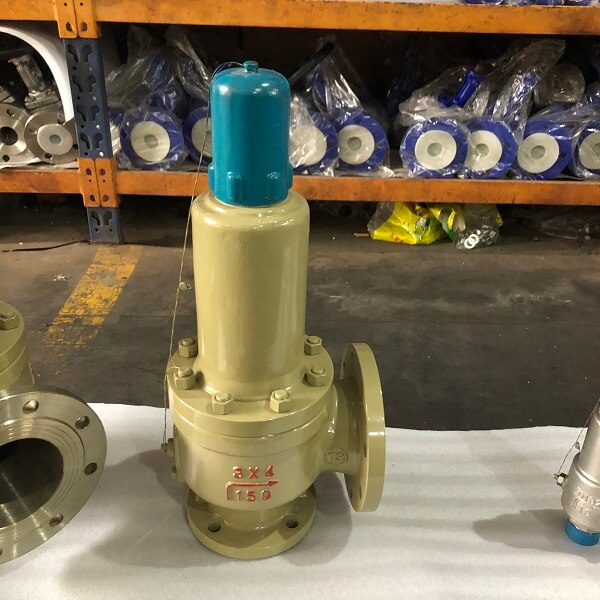
The seating surface in a safety valve is surprisingly small. In a 3×4 valve, the seating surface is 1/8″ wide and 5″ around. All it takes is one pop with a piece of debris going through and it can leak. Here’s an example: Folgers had a plant in downtown Kansas City that had a 6×8 DISCONTINUED Consolidated 1411Q set at 15 psig. The valve was probably 70 years old. We repaired it, but it leaked when plant maintenance put it back on. It was after a reducing valve, and I asked him if he played with the reducing valve and brought the pressure up to pop the safety valve. He said no, but I didn’t believe him. I told him the valve didn’t leak when it left our shop and to send it back.
If there is a problem with a safety valve, 99% of the time it is not the safety valve or the company that set it. There may be other reasons that the pressure is rising in the system before the safety valve. Some ethanol plants have a problem on starting up their boilers. The valves are set at 150 and they operate at 120 but at startup the pressure gets away from them and there is a spike, which creates enough pressure to cause a leak until things get under control.
If your customer is complaining that the valve is leaking, ask questions before a replacement is sent out. What is the operating pressure below the safety valve? If it is too close to the set pressure then they have to lower their operating pressure or raise the set pressure on the safety valve.
Is the valve installed in a vertical position? If it is on a 45-degree angle, horizontal, or upside down then it needs to be corrected. I have heard of two valves that were upside down in my 47 years. One was on a steam tractor and the other one was on a high-pressure compressor station in the New Mexico desert. He bought a 1/4″ valve set at 5,000 psig. On the outlet side, he left the end cap in the outlet and put a pin hole in it so he could hear if it was leaking or not. He hit the switch and when it got up to 3,500 psig the end cap came flying out like a missile past his nose. I told him to turn that sucker in the right direction and he shouldn’t have any problems. I never heard from him so I guess it worked.
If the set pressure is correct, and the valve is vertical, ask if the outlet piping is supported by something other than the safety valve. If they don’t have pipe hangers or a wall or something to keep the stress off the safety valve, it will leak.
There was a plant in Springfield, Mo. that couldn’t start up because a 2″ valve was leaking on a tank. It was set at 750 psig, and the factory replaced it 5 times. We are not going to replace any valves until certain questions are answered. I was called to solve the problem. The operating pressure was 450 so that wasn’t the problem. It was in a vertical position so we moved on to the piping. You could tell the guy was on his cell phone when I asked if there was any piping on the outlet. He said while looking at the installation that he had a 2″ line coming out into a 2×3 connection going up a story into a 3×4 connection and going up another story. I asked him if there was any support for this mess, and he hung up the phone. He didn’t say thank you, goodbye, or send me a Christmas present.
Operating controls for boilers could be broadly defined to include burner management controls; however, this inspector guide will be limited to the pressure and temperature operating controls required by the ASME BPV Code for steam and hot water boilers.
Steam boilers require a device which senses steam pressure and cycles the burner or other source of heat in order to maintain a consistent, predetermined operating pressure. A second device is used to prevent the boiler from exceeding the maximum allowable working pressure (MAWP) indicated on the boiler nameplate.
Hot-water boilers require a device which senses water temperature and cycles the burner or other source of heat in order to maintain a consistent, predetermined operating temperature. A second device is used to prevent the boiler from exceeding the design temperature of an ASME BPV Code Section I boiler or the maximum water temperature indicated on an ASME BPV Code Section IV boiler nameplate.
The secondary device referenced above for both steam and hot-water boilers is referred to as a high-limit control and under normal conditions, would never be called upon to operate. However, if the primary, or operating, control should fail, the high-limit control must operate, stopping the burner or other source of heat. Some high-limit controls incorporate a manual reset. The purpose of this is to alert the operator that the high-limit control has been activated. The operator should then look for the problem which caused the high-limit control to activate before resetting the device and restarting the boiler.
ASME BPV Code Section I does not specifically mandate pressure or temperature controls but they will be found, in one form or another, on almost all ASME BPV Code Section I boilers. In addition, ASME Standard CSD-1 (if applicable) requires the controls on boilers with input ratings up to 12,500,000 Btu/hr. Jurisdictional regulations will specify the use of ASME Standard CSD-1 if it is mandated.
A pressure control must be installed so as to always sense pressure from the steam space of the boiler. The ASME BPV Code requirements and device manufacturer"s instructions should be followed for any installation details. When a siphon or pigtail is used to prevent live steam from entering and damaging the device, the orientation of the siphon loop is critical to the proper operation of a device containing a mercury switch. If the siphon loop is installed in the incorrect orientation shown in Figure 1, movement of the loop caused by heat and/or pressure can cause the mercury switch in the device to activate or deactivate at other than the set pressure.
Either type of operating control can be bypassed electrically with jumper wires. Jumper wires can be used legitimately by qualified service personnel during maintenance and testing, but must be removed before returning the boiler to normal operation. Jumper wires could be used inappropriately in an attempt to permanently bypass a control which has malfunctioned and will not allow the boiler to operate.
While inspecting low-pressure or high-pressure boilers, the inspector will be observing operating controls. The inspector must take the time necessary to completely evaluate the condition and operational effectiveness of these controls. The inspector should:
Compare the pressure gage reading on a steam boiler with the set pressure of the primary operating control. If the pressure gage reading is higher than the set pressure of the control, request the installation of a second, reliable pressure gage in order to determine the accuracy of the first pressure gage. If the second pressure gage reading agrees with the operating control set pressure, the first pressure gage must be recalibrated or replaced. If, however, the second pressure gage reading agrees with the first pressure gage, the boiler should be removed from service until the primary operating control can be repaired or replaced.
Compare the thermometer reading on a hot-water boiler with the set temperature of the primary operating control. If the thermometer reading is higher than the set temperature of the control, request the installation of a second, reliable thermometer in order to determine the accuracy of the first thermometer. If the second thermometer reading agrees with the operating control set temperature, the first thermometer must be recalibrated or replaced. If, however, the second thermometer reading agrees with the first thermometer, the boiler should be removed from service until the primary operating control can be repaired or replaced
Request the owner or owner"s representative test the high-limit control in accordance with the control manufacturer"s instructions. This test may involve disabling the primary operating control or setting the primary control"s pressure or temperature, as applicable, higher than the setting of the high-limit control. Since each installation can be unique, the inspector should rely on the control manufacturer"s instructions for guidance. Before returning the boiler to its normal operating condition, ensure all operating controls are enabled and set to the proper pressure or temperature.
Additional information to aid inspections of operating controls, including installation requirements, can be found in the following publications and sources:

Tired of keeping track of your valve inventory’s annual certification records? We offer complete management of your safety relief valves. With an inventory of repair parts and in stock relief valves of all sizes, we can respond to any customer emergency. We offer annual certification services as well as repair of all major brands, including Kunkle, Conbraco, Consolidated, Dresser, Apollo and more.

Safety valves are an arrangement or mechanism to release a substance from the concerned system in the event of pressure or temperature exceeding a particular preset limit. The systems in the context may be boilers, steam boilers, pressure vessels or other related systems. As per the mechanical arrangement, this one get fitted into the bigger picture (part of the bigger arrangement) called as PSV or PRV that is pressure safety or pressure relief valves.
This type of safety mechanism was largely implemented to counter the problem of accidental explosion of steam boilers. Initiated in the working of a steam digester, there were many methodologies that were then accommodated during the phase of the industrial revolution. And since then this safety mechanism has come a long way and now accommodates various other aspects.
These aspects like applications, performance criteria, ranges, nation based standards (countries like United States, European Union, Japan, South Korea provide different standards) etc. manage to differentiate or categorize this safety valve segment. So, there can be many different ways in which these safety valves get differentiated but a common range of bifurcation is as follows:
The American Society of Mechanical Engineers (ASME) I tap is a type of safety valve which opens with respect to 3% and 4% of pressure (ASME code for pressure vessel applications) while ASME VIII valve opens at 10% over pressure and closes at 7%. Lift safety valves get further classified as low-lift and full lift. The flow control valves regulate the pressure or flow of a fluid whereas a balanced valve is used to minimize the effects induced by pressure on operating characteristics of the valve in context.
A power operated valve is a type of pressure relief valve is which an external power source is also used to relieve the pressure. A proportional-relief valve gets opened in a relatively stable manner as compared to increasing pressure. There are 2 types of direct-loaded safety valves, first being diaphragms and second: bellows. diaphragms are valves which spring for the protection of effects of the liquid membrane while bellows provide an arrangement where the parts of rotating elements and sources get protected from the effects of the liquid via bellows.
In a master valve, the operation and even the initiation is controlled by the fluid which gets discharged via a pilot valve. Now coming to the bigger picture, the pressure safety valves based segment gets classified as follows:
So all in all, pressure safety valves, pressure relief valves, relief valves, pilot-operated relief valves, low pressure safety valves, vacuum pressure safety valves etc. complete the range of safety measures in boilers and related devices.
Safety valves have different discharge capacities. These capacities are based on the geometrical area of the body seat upstream and downstream of the valve. Flow diameter is the minimum geometrical diameter upstream and downstream of the body seat.
The nominal size designation refers to the inlet orifice diameter. A safety Valve"s theoretical flowing capacity is the mass flow through an orifice with the same cross-sectional area as the valve"s flow area. This capacity does not account for the flow losses caused by the valve. The actual capacity is measured, and the certified flow capacity is the actual flow capacity reduced by 10%.
A safety valve"s discharge capacity is dependent on the set pressure and position in a system. Once the set pressure is calculated, the discharge capacity must be determined. Safety valves may be oversized or undersized depending on the flow throughput and/or the valve"s set pressure.
The actual discharge capacity of a safety valve depends on the type of discharge system used. In liquid service, safety valves are generally automatic and direct-pressure actuated.
A safety valve is used to protect against overpressure in a fluid system. Its design allows for a lift in the disc, indicating that the valve is about to open. When the inlet pressure rises above the set pressure, the guide moves to the open position, and media flows to the outlet via the pilot tube. Once the inlet pressure falls below the set pressure, the main valve closes and prevents overpressure. There are five criteria for selecting a safety valve.
The first and most basic requirement of a safety valve is its ability to safely control the flow of gas. Hence, the valve must be able to control the flow of gas and water. The valve should be able to withstand the high pressures of the system. This is because the gas or steam coming from the boiler will be condensed and fill the pipe. The steam will then wet the safety valve seat.
The other major requirement for safety valves is their ability to prevent pressure buildup. They prevent overpressure conditions by allowing liquid or gas to escape. Safety valves are used in many different applications. Gas and steam lines, for example, can prevent catastrophic damage to the plant. They are also known as safety relief valves. During an emergency, a safety valve will open automatically and discharge gas or liquid pressure from a pressurized system, preventing it from reaching dangerous levels.
The discharge capacity of a safety valve is based on its orifice area, set pressure, and position in the system. A safety valve"s discharge capacity should be calculated based on the maximum flow through its inlet and outlet orifice areas. Its nominal size is often determined by manufacturer specifications.
Its discharge capacity is the maximum flow through the valve that it can relieve, based on the maximum flow through each individual flow path or combined flow path. The discharge pressure of the safety valve should be more than the operating pressure of the system. As a thumb rule, the relief pressure should be 10% above the working pressure of the system.
It is important to choose the discharge capacity of a safety valve based on the inlet and output piping sizes. Ideally, the discharge capacity should be equal to or greater than the maximum output of the system. A safety valve should also be installed vertically and into a clean fitting. While installing a valve, it is important to use a proper wrench for installation. The discharge piping should slope downward to drain any condensate.
The discharge capacity of a safety valve is measured in a few different ways. The first is the test pressure. This gauge pressure is the pressure at which the valve opens, while the second is the pressure at which it re-closes. Both are measured in a test stand under controlled conditions. A safety valve with a test pressure of 10,000 psi is rated at 10,000 psi (as per ASME PTC25.3).
The discharge capacity of a safety valve should be large enough to dissipate a large volume of pressure. A small valve may be adequate for a smaller system, but a larger one could cause an explosion. In a large-scale manufacturing plant, safety valves are critical for the safety of personnel and equipment. Choosing the right valve size for a particular system is essential to its efficiency.
Before you use a safety valve, you need to know its discharge capacity. Here are some steps you need to follow to calculate the discharge capacity of a safety valve.
To check the discharge capacity of a safety valve, the safety valve should be installed in the appropriate location. Its inlet and outlet pipework should be thoroughly cleaned before installation. It is important to avoid excessive use of PTFE tape and to ensure that the installation is solid. The safety valve should not be exposed to vibration or undue stress. When mounting a safety valve, it should be installed vertically and with the test lever at the top. The inlet connection of the safety valve should be attached to the vessel or pipeline with the shortest length of pipe. It must not be interrupted by any isolation valve. The pressure loss at the inlet of a safety valve should not exceed 3% of the set pressure.
The sizing of a safety valve depends on the amount of fluid it is required to control. The rated discharge capacity is a function of the safety valve"s orifice area, set pressure, and position in the system. Using the manufacturer"s specifications for orifice area and nominal size of the valve, the capacity of a safety valve can be determined. The discharge flow can be calculated using the maximum flow through the valve or the combined flows of several paths. When sizing a safety valve, it"s necessary to consider both its theoretical and actual discharge capacity. Ideally, the discharge capacity will be equal to the minimum area.
To determine the correct set pressure for a safety valve, consider the following criteria. It must be less than the MAAP of the system. Set pressure of 5% greater than the MAAP will result in an overpressure of 10%. If the set pressure is higher than the MAAP, the safety valve will not close. The MAAP must never exceed the set pressure. A set pressure that is too high will result in a poor shutoff after discharge. Depending on the type of valve, a backpressure variation of 10% to 15% of the set pressure cannot be handled by a conventional valve.

Condemned boiler or unfired pressure vessel--A boiler or unfired pressure vessel which was inspected and declared unsafe or disqualified for use by the Department.
Internal inspection--An inspection made when a boiler or unfired pressure vessel is shut down and handholes, manholes, or other inspection openings are opened for inspection of the interior of the boiler or unfired pressure vessel.
Low pressure heating boiler--A steam boiler operated at a pressure not exceeding 15 psig or a hot water heating or hot water supply boiler operating at a pressure not exceeding 160 psig and a temperature not exceeding 250° F.
Miniature boiler--A boiler which is not more than 16 inches inside diameter of the shell, 5 cubic feet gross volume, excluding casing and insulation; 100 psig maximum allowable working pressure; and, 20 square feet of heating surface.
Process boiler--Any vessel in which steam is generated or superheated under pressure or for use external to itself by direct or indirect application of heat. The source of heat must be in part from a process other than the boiler itself. To be classified as a process boiler, the boiler must be directly tied to another process other than the generation of steam.
Not more than $50 plus the annual certificate fee shall be collected for any and all inspections as above of any low pressure boiler in any required inspection period.
(1) The boiler and the pipe connections up to and including the stop valve or valves nearest the boiler as required by the ASME Code and Power Piping, B31.1. Superheaters, reheaters, economizers and other pressure parts connected directly to the boiler without intervening valves will be considered as parts of the boiler and their construction must conform to ASME Code and Power Piping, B31.1 requirements.
(b) Boilers installed before July 1, 1916, and unfired pressure vessels and power boilers installed before September 1, 1937, must comply with §§ 3a.131--3a.154 (relating to boilers installed prior to July 1, 1916 and unfired pressure vessels and power boilers installed prior to September 1, 1937).
(7) Unfired pressure vessels used for the transportation of compressed gases that are operated in compliance with specifications and regulations of the United States Department of Transportation (49 CFR Part 173 (relating to shippers general requirements for shipments and packaging)).
(10) Vessels having an internal or external operating pressure of no more than 15 psi with no limitation on size when equipped with approved safety devices.
(e) The Department will issue a Pennsylvania credential card and commission to an applicant who meets the requirements of subsection (c) and pays the required fee under § 3a.2 (relating to fees).
(a) The Department will issue a certificate of competency, credential card and commission to an applicant who passes an examination for inspector, meets the requirements of this part and pays the required fee under § 3a.2 (relating to fees).
(6) Having a commission or any other authorization to engage in the business of boiler inspection revoked or suspended or having other disciplinary action taken, surrendering a commission or other authorization in lieu of discipline, or having an application for a commission or authorization to engage in the business of boiler inspection refused or denied by the National Board, the proper authority of another state or Federal district, territory, insular possession of the United States or Canada.
(10) Pleading guilty, entering a plea of nolo contendere, being found guilty, receiving probation without verdict, disposition in lieu of trial or an Accelerated Rehabilitative Disposition for any felony or for any other crime relating to boiler inspection in the courts of this Commonwealth, a Federal court, a court of any other state, territory or insular possession of the United States or a court of Canada.
(1) The Department will serve the boiler inspector with an order to show cause under 1 Pa. Code § 35.14 (relating to orders to show cause). The order to show cause will contain notification that the certification may be subject to action and the grounds for the action. The order to show cause will require that the boiler inspector respond in writing within 30 days after the date of service of the order. The Department will also serve a copy of the order to show cause upon the boiler inspector"s current employer, if any.
(2) The boiler inspector shall file an answer in writing to the allegations set forth in the order to show cause in accordance with 1 Pa. Code § 35.37 (relating to answers to orders to show cause). If made, answers must be filed with the Department at the appropriate address within 30 days after the date of service of the order to show cause. Failure to file an answer will result in the entry of a default judgment against the inspector.
(a) A boiler or unfired pressure vessel destined for use in this Commonwealth must be built to the applicable ASME code of construction or meet the requirements of section 7 of the act (35 P. S. § 1331.7).
(b) A boiler or unfired pressure vessel built to the ASME Code must be stamped with the appropriate ASME symbol, the manufacturer"s information in accordance with stamping requirements of the code of construction, and its National Board registration number. The stamping may be applied to a nameplate in accordance with the code of construction.
(c) National Board registration and stamping requirements do not apply to cast iron boilers, which are constructed under ASME Code provisions and do not require final inspection by a National Board inspector.
(d) A new boiler or unfired pressure vessel installed in this Commonwealth must be stamped with an identifying serial number consisting of the keystone symbol and figures, which may not be less than 5/16 inches in height and arranged as follows:
(e) A boiler or unfired pressure vessel that is not built to the ASME Code may be stamped with a Pennsylvania special number if it meets the requirements of section 7(b) of the act.
(f) The Department may accept a boiler or unfired pressure vessel with a registration number from another state for use in this Commonwealth if a National Board inspector inspected and approved the boiler or unfired pressure vessel during construction.
A boiler or unfired pressure vessel stamped with the ASME symbol and another state stamp may be installed and operated if a National Board inspector witnessed its construction and the shop data report is provided to the Department with a completed Department-provided intent to install form under § 3a.98 (relating to plan approval).
The shell or drum of a boiler or unfired pressure vessel containing a lap seam crack along a longitudinal riveted joint shall be immediately taken out of service. Repairs may not be made without Department approval.
(b) Hand-controlled bypasses around reducing valves may be used if the bypass has no greater capacity than the reducing valve. Hand control bypasses may be used around reducing valves at greater capacity than the reducing valve if the system or unfired pressure vessel has adequate relief or safety valve protection, or meets the requirements of the high pressure system.
(a) A boiler or unfired pressure vessel must be protected by safety relief devices, and indicating and controlling devices sufficient to insure its safe operation which meet all of the following requirements:
(2) The devices must having sufficient relieving capacity to prevent a rise of pressure in the boiler or unfired pressure vessel of more than 10% above the maximum allowable working pressure, taking into account the effect of static head.
(b) Safety valves for other than noxious liquids or toxic vapors must be direct spring-loaded type valves, designed with substantial lifting devices so that the disk can be lifted from its seat by the spindle of at least 1/8 the diameter of the valve if the pressure of the vessel is at 75% of the safety valve setting.
(c) Each safety valve must have clear manufacturer markings that are 1/4-inch or larger. The markings must contain all of the following information stamped on the valve, cast on the valve body, or cast on a plate securely fastened to the valve:
(d) If the valve inlet is not threaded, the initial diameter of the inlet may not be less than the inside diameter of a standard pipe of the same size.
(f) Existing safety valves bearing ASME stamping different from the requirements in subsection (c) are permitted if the safety valves have equivalent construction and relieving capacity.
(i) A boiler or unfired pressure vessel in which pressure is not generated and is derived from an outside source shall have a safety device connected to the vessel or system which it protects in a manner to prevent a rise in pressure beyond the maximum allowable pressure.
(j) A boiler or unfired pressure vessel in which pressure may be generated must have a safety device or devices connected directly to the vessel and comply with all of the following:
(1) When the contents of a vessel may cause interference with the operation of the vessel or safety valve when the safety value is directly attached, the safety valve or valves may be connected in a manner to avoid the interference.
(2) An escape pipe may be used. The pipe must be full sized and fitted with an open drain to prevent liquid from lodging in the upper part of the safety valve. A valve may not be placed on the escape pipe between the safety valve and the atmosphere.
(3) An elbow may be placed on an escape pipe if it is located close to the safety valve outlet or the escape pipe is securely anchored and supported. If two or more safety devices are placed on one connection, the connection must have a cross sectional area at least equal to the combined area of the safety devices" inlets.
(k) Every safety valve which is exposed to temperatures of 32°F or less must have a drain of at least 3/8 inch in diameter at the lowest point where water can collect.
(l) A spring in a safety or relief valve in service for pressures 250 psi and less may not be reset for a pressure more than 10% above or 19% below the pressure at which the valve is marked. For pressures higher than 250 psi, the spring may not be reset for any pressure more than 5% above or 50% below the pressure at which the safety or relief valve is marked.
(m) Safety valves for compressed air tanks cannot be larger than 3-inch diameter. The valves must be proportioned for the maximum number of cubic feet of free air that may be applied per minute.
(n) A rupture disk may be used as a pressure safety device on boilers or unfired pressure vessels containing nontoxic gases, when it is designed to fail at not more than the design pressure of the vessel.
(p) A company or organization holding a Department-issued certificate of authorization to reset and reseal safety valves and relief valves or a current VR stamp is required to reset and reseal safety valves and relief valves.
(r) A safety valve or relief valve may not be loaded to maintain a working pressure in excess of the maximum working pressure stated on the boiler or unfired pressure vessel"s certificate of operation.
(s) Additional or supplemental safety or relief valves installed on a boiler or unfired pressure vessel, may exceed maximum working pressure if the valves comply with the applicable code of construction or this chapter.
(a) At least one safety valve on each boiler must be set at or below the maximum allowable working pressure. All other valves may be set within a range of 3.0% above the maximum allowable working pressure. The range of setting of all of the saturated steam valves on the boiler may not exceed 10% of the saturated steam valve set at the highest pressure.
(b) When a boiler system is comprised of boilers with different maximum allowable working pressures having minimum safety valve settings varying more than 6% and connected so that steam flows toward the lower pressure boiler, the boiler system must meet one of the following requirements:
(a) Blowoff piping from a power boiler or a miniature boiler may not discharge directly into a sewer. A blowoff tank will be used if conditions do not provide an adequate and safe open discharge.
(e) Vents must lead as directly as possible to the outer air and discharge in a safe location. There may be no valve or other obstructions such as water pockets between the tank and the discharge end of the vent pipe.
Discharge of safety valves of a boiler generating in excess of 500 pounds of steam per hour must be piped to the outside atmosphere and to a safe point of discharge. Blowoff pipes and other outlets must be located to prevent injury to personnel.
(1) A cable must be provided for grounding the boiler shell and shall be the same gauge as the incoming power line to the boiler. The cable must be permanently connected and grounded.
(ii) A conductor will be permanently attached to the boiler shell by suitable lugs, pressure connectors, clamps, or other Department-approved means. Connectors that depend on solder to maintain connection may not be used.
(a) A boiler or unfired pressure vessel must be supported by masonry or structural supports sufficient to safely support the boiler or vessel and its contents.
Stoker coal fired boilers under positive pressure must be equipped with explosion doors to relieve furnace pressure. The explosion doors must be located in the setting wall within 7 feet of the firing floor or any platform, and must be provided with substantial deflectors to divert the blast away from personnel.
(a) Walkways, runways and platforms are required between and on top of boilers, which are more than 8-feet high from the operating floor to afford accessibility for the operation and servicing.
(b) The following requirements apply to a single installation or assembly of storage water heaters or instantaneous water heaters, which operate as a unit:
(f) The clearance between modules in a modular system may be reduced to the manufacturer"s recommendations if the entire modular boiler system meets the 30-inch clearance requirement of subsection (a)(1).
(a) The owner or user of a new boiler or unfired pressure vessel having unusual features of special design intended for installation and operation in this Commonwealth shall submit all of the following to the Department for approval:
(2) Drawings that show all details of the proposed construction and the method of computation used in determining the safe working pressure for each new boiler and unfired pressure vessel.
Parts manufactured for boilers or unfired pressure vessels constructed to the ASME Code must be manufactured and stamped in accordance with the applicable section of the ASME Code. Data reports must be furnished in accordance with the applicable section of the ASME Code.
(a) An installer of low-pressure steel heating boilers shall provide a copy of the manufacturer"s data report to the inspector when the boiler is installed.
(c) An installer of low-pressure cast iron boilers shall submit a "Cast Iron Installation Report" to the Department on a Department-provided form. The Cast Iron Installation Report contains manufacturer, testing and installation information.
(a) An owner or user of a boiler or unfired pressure vessel shall consult with an inspector on a repair that affects the working pressure or safety of a boiler or unfired pressure vessel.
(b) A repair to a boiler or unfired pressure vessel must comply with the applicable provisions of the ASME Code or ANSI/NB 23. A manufacturer or repair company may not perform welded repairs and tube replacements without holding an "R" Stamp.
(c) An owner or user of a boiler or unfired pressure vessel shall consult with the inspector responsible for completing the report of welded repair before commencement of work or repairs that alter the original design of a boiler or unfired pressure vessel. A manufacturer or repair company holding an ANSI/NB 23 "R" stamp may perform alterations to other vessels.
(e) An owner or user of a boiler or unfired pressure vessel that requires an inspection under this chapter shall immediately notify the Department when a defect affecting the safety of the boiler or unfired pressure vessel is discovered.
Workmanship, materials, fittings and attachments used in the reconstruction or repair of a boiler or unfired pressure vessel must meet ANSI/NB 23. The boiler or unfired pressure vessel may not become operational until an inspector approves all repairs.
(b) A repair to a boiler or unfired pressure vessel that involves welding may be made if an inspector approves the repair and signs a record of welded repairs.
(a) The Department will issue a certificate of operation for a boiler or unfired pressure vessel upon receipt of an inspection report indicating that the boiler or unfired pressure vessel is safe to operate at the pressure limit listed in the inspection report.
The Department will suspend the certificate of operation and seal a boiler or unfired pressure vessel that is unsafe. A person, firm, partnership or corporation operating a boiler or unfired pressure vessel with a suspended certificate of operation is subject to the penalties of section 19 of the act. (35 P. S. § 1331.19)
(a) Under section 16 of the act (35 P. S. § 1331.16), the owner, user or operator shall immediately notify the Department by telephone, facsimile transmission, electronic mail or messenger of an accident or explosion. Immediate notification means within 24 hours of the accident. The owner, user or operator shall file a written report with the Department on the Department’s boiler accident report form within 5 days of the accident. The boiler accident report form may be obtained on the Department’s website.
(b) The boiler or unfired pressure vessel, its parts or equipment involved in the accident or explosion may not be removed or disturbed before a Department inspection is made except to prevent harm to persons or property.
(a) An inspector will instruct the owner or user to restamp a boiler or unfired pressure vessel when the stamping becomes indistinct or detached. The owner or user shall submit a request for restamping the boiler or unfired pressure vessel to the Department. The request must be accompanied with proof of the original stamping consisting of a rubbing of the original stamping or a copy of the manufacturer"s data sheet.
(a) A Department inspector will stamp an unsafe boiler or unfired pressure vessel by crossing out the serial number stamping. The following designation will be used:
(c) A Department inspector will remove the stamping of subsection (a) when a boiler or unfired pressure vessel has been restored or repaired to comply with this chapter. No other person may remove the stamping.
An owner or user shall notify the Department when a boiler or unfired pressure vessel is removed from service for a repair or alteration within 10 days.
(b) The owner or user of a boiler or unfired pressure vessel shall notify the Department within 10 days of the new location of a boiler or unfired pressure vessel that is moved.
(b) A boiler owner shall submit an intent to install form or other data showing compliance with the act and this chapter to the Department before a boiler is installed.
(c) A boiler owner shall submit drawings and a request for a variance to the Industrial Board if the installation clearances do not meet the requirements of § 3a.36 (relating to clearances). Drawings must be at least 18 inches by 24 inches in size drawn to a scale of not less than 1/4 inch equals 1 foot. Drawings for boiler installations must include the following:
(2) The proposed location of all boilers, drums, headers, doors, steam, air and water gages, safety devices, blowoffs, all necessary piping, and all other parts and equipment.
(1) The Department will issue a written notice of deficiency to the boiler or unfired pressure vessel owner or user. The notice will contain a description of the violations and an order requiring correction of the violations and repairs within 30 days of the date of issuance. When a violation relates to the unsafe operation of a boiler, the Department will act under § 3a.92 (relating to unsafe operation).
(2) The written notice of deficiency will include a certification requiring the boiler or unfired pressure vessel owner or user to sign, date and return the certification when the corrective action or repair has occurred. The Department will inspect boilers or unfired pressure vessels which have been placed out of service to verify the corrective action or repair. The Department must approve the corrective action or repair before the boiler or unfired pressure vessel is returned to service.
(3) If the boiler or unfired pressure vessel owner or user does not correct the deficiency within the period of time allowed in the notice of deficiency, the Department may initiate action to seal the boiler or unfired pressure vessel by issuing an order to show cause to the boiler or unfired pressure vessel owner or user.
(4) The order to show cause must contain a statement of the grounds for the action, the alleged violations of the act and this chapter and notification that the boiler or unfired pressure vessel may be sealed. The order to show cause must contain notification that the owner or user shall submit a written answer within 30 days. The Department will serve the order to show cause upon the owner or user by certified mail or personal service.
(b) The Department will consider a timely-filed request for variance or extension of time, or a timely-filed appeal as a stay to an enforcement action unless the Department acts under § 3a.92 (relating to unsafe operation) or the boiler constitutes a danger to life or property under section 10(e) of the act (35 P. S. § 1331.10(e)).
(c) The Department will inspect the boiler or unfired pressure vessel at the expiration of an extension of time or other time period granted for compliance under this section. If the boiler or unfired pressure vessel violates the act or this chapter following inspection, the Department may seal or condemn the boiler or unfired pressure vessel under section 13 of the act (35 P. S. § 1331.13). The Department will serve the seal order upon the owner or user by certified mail or personal service.
(d) Under section 13 of the act, the Department will issue a notice to discontinue operation to the boiler or unfired pressure vessel owner or user for a violation that was not corrected. The notice to discontinue operation will require the owner or user to discontinue the use of the boiler or unfired pressure vessel within 24 hours. The boiler or unfired pressure vessel may not be returned to service until the violations have been corrected, the repairs have been made and the Department notifies the owner or user that the boiler or unfired pressure vessel may be returned to service.
Field inspections shall be conducted by an individual holding a current Pennsylvania Inspector Commission to inspect boilers and unfired pressure vessels in this Commonwealth. Field inspections shall be conducted according to the following timetable:
(1) Power boilers and process boilers will be inspected internally and externally while not under pressure every 12 months except as provided under section 9(e) and (f) of the act (35 P. S. § 1331.9(e) and (f)).
(2) The Department may extend power boiler internal inspections to 24 months and process boiler internal inspections to 60 months if the boiler passes an annual external inspection and all the following requirements are met:
(i) There is continuous boiler water treatment under the direct supervision of a person trained and experienced in water treatment for controlling and limiting corrosion and deposits.
(B) Daily analysis of water samples showing water conditions and elements or characteristics that produce corrosion or other deterioration to the boiler or its parts.
(4) External inspection of hot water supply boilers will be conducted every 24 months. An inspector may require internal inspection because of a vessel"s age or condition. The Department will notify the boiler owner or operator verbally or in writing of the need for an internal inspection.
(7) External inspections of cast iron boilers will be conducted every 24 months and will include an internal inspection of the firebox. The unit shall be flushed until clean if the watersides appear to contain sludge.
(8) Unfired pressure vessels will be inspected every 36 months. An inspector may require internal inspections because of a vessel"s age or condition. The Department will notify the boiler owner or operator verbally or in writing of the need for an internal inspection.
(a) An owner or user shall prepare a boiler or unfired pressure vessel for internal inspection in accordance with the ANSI/NB23 after a inspector provides notification.
An owner or user shall remove a portion of the jacketing, setting wall or other form of casing or housing so an inspector may view rivet size and pitch, and other data necessary to determine the safety of a boiler or unfired pressure vessel when a portion of the jacketing, setting wall or other form of casing or housing is not visible and there is no other means to obtain this information.
(4) A safety valve must be removed or each valve shall be held to its seat by a testing clamp. Screwing down the compression screw upon the spring is prohibited. A VR stamp holder must reseal the valves.
(5) Pressure must be equal to or below the release pressure of the safety valve having the highest release setting when a test is applied to an existing installation to determine tightness.
Fire-actuated fusible plugs may be used if the plugs conform to the requirements of Sections A19--A21, Appendix A, section I of the ASME Code. The plugs must be replaced annually.
The maximum allowable working pressure on the shell of a welded steel or wrought iron heating boiler may not exceed the requirements of ASME Code, section IV.
(a) The maximum allowable working pressure on the shell of a cast iron boiler may not exceed 15 psig for a steam boiler and the stamped working pressure for a hot water boiler.
(b) The maximum allowable working pressure for a boiler having a cast iron shell or heads, and steel or wrought iron tubes may not exceed 15 psig for a steam boiler and the stamped working pressure for a hot water boiler.
An inspector may reduce the operating pressure of a heating boiler if the inspector determines that the boiler is unsafe for operation at the approved pressure and the boiler is not properly repaired. The inspector may reduce the operating pressure based upon the remaining thickness of the pressure boundaries and code of construction requirements.
(b) A heating system equipped with a steam stop valve must have a check valve in the condensate return pipe from the part of the system equipped with the steam stop valve.
(a) A modular boiler as defined in ASME Code, section IV must be installed in accordance with § 3a.36 (relating to clearances). The distance between modules may be reduced to the manufacturer"s recommendations if the entire modular boiler system meets the 30-inch clearance requirements.
(b) A modular boiler must have only one inlet and one outlet valve, as required by ASME Code, section IV. The boiler controls must comply with ASME Code, section IV and ASME/CSD1.
(c) The clearance on one side of a boiler mounted in a covered trailer may be reduced to 3 inches if the trailer has access panels for removal of handhole plugs for inspection and maintenance.
(d) The user or operator shall notify the Department in writing and obtain written Department approval before a portable boiler is moved and placed in service.
(b) A storage vessel may be used with a fired coil water heater and instantaneous water heater, if its controls comply with ASME CSD1, and it meets the ASME Code over-pressure protection requirements. The vessel must be ASME Code constructed if the BTU input exceeds 200,000 BTU.
(a) A storage water heater must be installed in accordance with ASME Code, section IV, articles HLW 700 and HLW 800, and comply with safety valve requirements of ASME CSD1.
(a) The design and construction of a steam/hot water coil storage water heater must comply with ASME Code, section VIII and the additional control requirements of ASME/CSD1.
(a) A miniature boiler must be manufactured under the ASME "S," "H" or "M" Code. A boiler manufactured under ASME "S" and "H" Code must be stamped with a National Board registration number.
(b) Clearance requirements contained in § 3a.36 (relating to clearances) do not govern a miniature boiler or kitchen equipment if all pressure containing parts with appurtenances are visible for inspection.
(c) A pressure-relieving device must be sized in accordance with the data plate for pressure. The capacity must be based on the pressure and pipe size or the total BTU valve of the boiler.
(f) Inspection of fuel trains and piping systems shall be determined by the type of boiler to which the system is attached and performed in accordance with § 3a.111 (relating to field inspections).
(a) A swimming pool heater is an instantaneous water heater. The heater must meet the construction requirements of ASME Code, section IV and the control requirements of ASME/CSD1 except if exempt under § 3a.3(d) (relating to scope).

A series of anomalies occurred in the boiler room that evening. The steel compression tank for the hydronic loop flooded, leaving no room for expansion. Water will expand at 3% of its volume when heated from room temperature to 180° F. When the burner fired, the expansion of the water increased the system pressure within the boiler. The malfunctioning operating control did not shut off the burner at the set point which caused the relief valve to open.
The brass relief valve discharge was installed with copper tubing piped solid to a 90° ell on the floor and the tubing further extended to the floor drain. The combination of hot water and steam from the boiler caused the discharge copper tubing to expand,


 8613371530291