
boiler safety valve setting pressure free sample

In order to ensure that the maximum allowable accumulation pressure of any system or apparatus protected by a safety valve is never exceeded, careful consideration of the safety valve’s position in the system has to be made. As there is such a wide range of applications, there is no absolute rule as to where the valve should be positioned and therefore, every application needs to be treated separately.
A common steam application for a safety valve is to protect process equipment supplied from a pressure reducing station. Two possible arrangements are shown in Figure 9.3.3.
The safety valve can be fitted within the pressure reducing station itself, that is, before the downstream stop valve, as in Figure 9.3.3 (a), or further downstream, nearer the apparatus as in Figure 9.3.3 (b). Fitting the safety valve before the downstream stop valve has the following advantages:
• The safety valve can be tested in-line by shutting down the downstream stop valve without the chance of downstream apparatus being over pressurised, should the safety valve fail under test.
• When setting the PRV under no-load conditions, the operation of the safety valve can be observed, as this condition is most likely to cause ‘simmer’. If this should occur, the PRV pressure can be adjusted to below the safety valve reseat pressure.
Indeed, a separate safety valve may have to be fitted on the inlet to each downstream piece of apparatus, when the PRV supplies several such pieces of apparatus.
• If supplying one piece of apparatus, which has a MAWP pressure less than the PRV supply pressure, the apparatus must be fitted with a safety valve, preferably close-coupled to its steam inlet connection.
• If a PRV is supplying more than one apparatus and the MAWP of any item is less than the PRV supply pressure, either the PRV station must be fitted with a safety valve set at the lowest possible MAWP of the connected apparatus, or each item of affected apparatus must be fitted with a safety valve.
• The safety valve must be located so that the pressure cannot accumulate in the apparatus viaanother route, for example, from a separate steam line or a bypass line.
It could be argued that every installation deserves special consideration when it comes to safety, but the following applications and situations are a little unusual and worth considering:
• Fire - Any pressure vessel should be protected from overpressure in the event of fire. Although a safety valve mounted for operational protection may also offer protection under fire conditions,such cases require special consideration, which is beyond the scope of this text.
• Exothermic applications - These must be fitted with a safety valve close-coupled to the apparatus steam inlet or the body direct. No alternative applies.
• Safety valves used as warning devices - Sometimes, safety valves are fitted to systems as warning devices. They are not required to relieve fault loads but to warn of pressures increasing above normal working pressures for operational reasons only. In these instances, safety valves are set at the warning pressure and only need to be of minimum size. If there is any danger of systems fitted with such a safety valve exceeding their maximum allowable working pressure, they must be protected by additional safety valves in the usual way.
In order to illustrate the importance of the positioning of a safety valve, consider an automatic pump trap (see Block 14) used to remove condensate from a heating vessel. The automatic pump trap (APT), incorporates a mechanical type pump, which uses the motive force of steam to pump the condensate through the return system. The position of the safety valve will depend on the MAWP of the APT and its required motive inlet pressure.
This arrangement is suitable if the pump-trap motive pressure is less than 1.6 bar g (safety valve set pressure of 2 bar g less 0.3 bar blowdown and a 0.1 bar shut-off margin). Since the MAWP of both the APT and the vessel are greater than the safety valve set pressure, a single safety valve would provide suitable protection for the system.
However, if the pump-trap motive pressure had to be greater than 1.6 bar g, the APT supply would have to be taken from the high pressure side of the PRV, and reduced to a more appropriate pressure, but still less than the 4.5 bar g MAWP of the APT. The arrangement shown in Figure 9.3.5 would be suitable in this situation.
Here, two separate PRV stations are used each with its own safety valve. If the APT internals failed and steam at 4 bar g passed through the APT and into the vessel, safety valve ‘A’ would relieve this pressure and protect the vessel. Safety valve ‘B’ would not lift as the pressure in the APT is still acceptable and below its set pressure.
It should be noted that safety valve ‘A’ is positioned on the downstream side of the temperature control valve; this is done for both safety and operational reasons:
Operation - There is less chance of safety valve ‘A’ simmering during operation in this position,as the pressure is typically lower after the control valve than before it.
Also, note that if the MAWP of the pump-trap were greater than the pressure upstream of PRV ‘A’, it would be permissible to omit safety valve ‘B’ from the system, but safety valve ‘A’ must be sized to take into account the total fault flow through PRV ‘B’ as well as through PRV ‘A’.
A pharmaceutical factory has twelve jacketed pans on the same production floor, all rated with the same MAWP. Where would the safety valve be positioned?
One solution would be to install a safety valve on the inlet to each pan (Figure 9.3.6). In this instance, each safety valve would have to be sized to pass the entire load, in case the PRV failed open whilst the other eleven pans were shut down.
If additional apparatus with a lower MAWP than the pans (for example, a shell and tube heat exchanger) were to be included in the system, it would be necessary to fit an additional safety valve. This safety valve would be set to an appropriate lower set pressure and sized to pass the fault flow through the temperature control valve (see Figure 9.3.8).

Boiler explosions have been responsible for widespread damage to companies throughout the years, and that’s why today’s boilers are equipped with safety valves and/or relief valves. Boiler safety valves are designed to prevent excess pressure, which is usually responsible for those devastating explosions. That said, to ensure that boiler safety valves are working properly and providing adequate protection, they must meet regulatory specifications and require ongoing maintenance and periodic testing. Without these precautions, malfunctioning safety valves may fail, resulting in potentially disastrous consequences.
Boiler safety valves are activated by upstream pressure. If the pressure exceeds a defined threshold, the valve activates and automatically releases pressure. Typically used for gas or vapor service, boiler safety valves pop fully open once a pressure threshold is reached and remain open until the boiler pressure reaches a pre-defined, safe lower pressure.
Boiler relief valves serve the same purpose – automatically lowering boiler pressure – but they function a bit differently than safety valves. A relief valve doesn’t open fully when pressure exceeds a defined threshold; instead, it opens gradually when the pressure threshold is exceeded and closes gradually until the lower, safe threshold is reached. Boiler relief valves are typically used for liquid service.
There are also devices known as “safety relief valves” which have the characteristics of both types discussed above. Safety relief valves can be used for either liquid or gas or vapor service.
Nameplates must be fastened securely and permanently to the safety valve and remain readable throughout the lifespan of the valve, so durability is key.
The National Board of Boiler and Pressure Vessel Inspectors offers guidance and recommendations on boiler and pressure vessel safety rules and regulations. However, most individual states set forth their own rules and regulations, and while they may be similar across states, it’s important to ensure that your boiler safety valves meet all state and local regulatory requirements.
The National Board published NB-131, Recommended Boiler and Pressure Vessel Safety Legislation, and NB-132, Recommended Administrative Boiler and Pressure Vessel Safety Rules and Regulationsin order to provide guidance and encourage the development of crucial safety laws in jurisdictions that currently have no laws in place for the “proper construction, installation, inspection, operation, maintenance, alterations, and repairs” necessary to protect workers and the public from dangerous boiler and pressure vessel explosions that may occur without these safeguards in place.
The American Society of Mechanical Engineers (ASME) governs the code that establishes guidelines and requirements for safety valves. Note that it’s up to plant personnel to familiarize themselves with the requirements and understand which parts of the code apply to specific parts of the plant’s steam systems.
High steam capacity requirements, physical or economic constraints may make the use of a single safety valve impossible. In these cases, using multiple safety valves on the same system is considered an acceptable practice, provided that proper sizing and installation requirements are met – including an appropriately sized vent pipe that accounts for the total steam venting capacity of all valves when open at the same time.
The lowest rating (MAWP or maximum allowable working pressure) should always be used among all safety devices within a system, including boilers, pressure vessels, and equipment piping systems, to determine the safety valve set pressure.
Avoid isolating safety valves from the system, such as by installing intervening shut-off valves located between the steam component or system and the inlet.
Contact the valve supplier immediately for any safety valve with a broken wire seal, as this indicates that the valve is unsafe for use. Safety valves are sealed and certified in order to prevent tampering that can prevent proper function.
Avoid attaching vent discharge piping directly to a safety valve, which may place unnecessary weight and additional stress on the valve, altering the set pressure.
A little product education can make you look super smart to customers, which usually means more orders for everything you sell. Here’s a few things to keep in mind about safety valves, so your customers will think you’re a genius.
A safety valve is required on anything that has pressure on it. It can be a boiler (high- or low-pressure), a compressor, heat exchanger, economizer, any pressure vessel, deaerator tank, sterilizer, after a reducing valve, etc.
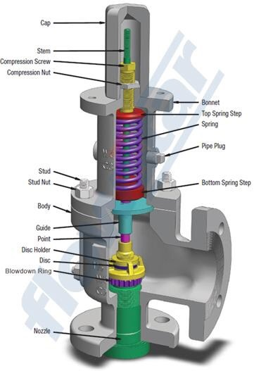
There are four main types of safety valves: conventional, bellows, pilot-operated, and temperature and pressure. For this column, we will deal with conventional valves.
A safety valve is a simple but delicate device. It’s just two pieces of metal squeezed together by a spring. It is passive because it just sits there waiting for system pressure to rise. If everything else in the system works correctly, then the safety valve will never go off.
A safety valve is NOT 100% tight up to the set pressure. This is VERY important. A safety valve functions a little like a tea kettle. As the temperature rises in the kettle, it starts to hiss and spit when the water is almost at a boil. A safety valve functions the same way but with pressure not temperature. The set pressure must be at least 10% above the operating pressure or 5 psig, whichever is greater. So, if a system is operating at 25 psig, then the minimum set pressure of the safety valve would be 30 psig.
Most valve manufacturers prefer a 10 psig differential just so the customer has fewer problems. If a valve is positioned after a reducing valve, find out the max pressure that the equipment downstream can handle. If it can handle 40 psig, then set the valve at 40. If the customer is operating at 100 psig, then 110 would be the minimum. If the max pressure in this case is 150, then set it at 150. The equipment is still protected and they won’t have as many problems with the safety valve.
Here’s another reason the safety valve is set higher than the operating pressure: When it relieves, it needs room to shut off. This is called BLOWDOWN. In a steam and air valve there is at least one if not two adjusting rings to help control blowdown. They are adjusted to shut the valve off when the pressure subsides to 6% below the set pressure. There are variations to 6% but for our purposes it is good enough. So, if you operate a boiler at 100 psig and you set the safety valve at 105, it will probably leak. But if it didn’t, the blowdown would be set at 99, and the valve would never shut off because the operating pressure would be greater than the blowdown.
All safety valves that are on steam or air are required by code to have a test lever. It can be a plain open lever or a completely enclosed packed lever.
Safety valves are sized by flow rate not by pipe size. If a customer wants a 12″ safety valve, ask them the flow rate and the pressure setting. It will probably turn out that they need an 8×10 instead of a 12×16. Safety valves are not like gate valves. If you have a 12″ line, you put in a 12″ gate valve. If safety valves are sized too large, they will not function correctly. They will chatter and beat themselves to death.
Safety valves need to be selected for the worst possible scenario. If you are sizing a pressure reducing station that has 150 psig steam being reduced to 10 psig, you need a safety valve that is rated for 150 psig even though it is set at 15. You can’t put a 15 psig low-pressure boiler valve after the reducing valve because the body of the valve must to be able to handle the 150 psig of steam in case the reducing valve fails.
The seating surface in a safety valve is surprisingly small. In a 3×4 valve, the seating surface is 1/8″ wide and 5″ around. All it takes is one pop with a piece of debris going through and it can leak. Here’s an example: Folgers had a plant in downtown Kansas City that had a 6×8 DISCONTINUED Consolidated 1411Q set at 15 psig. The valve was probably 70 years old. We repaired it, but it leaked when plant maintenance put it back on. It was after a reducing valve, and I asked him if he played with the reducing valve and brought the pressure up to pop the safety valve. He said no, but I didn’t believe him. I told him the valve didn’t leak when it left our shop and to send it back.
If there is a problem with a safety valve, 99% of the time it is not the safety valve or the company that set it. There may be other reasons that the pressure is rising in the system before the safety valve. Some ethanol plants have a problem on starting up their boilers. The valves are set at 150 and they operate at 120 but at startup the pressure gets away from them and there is a spike, which creates enough pressure to cause a leak until things get under control.
If your customer is complaining that the valve is leaking, ask questions before a replacement is sent out. What is the operating pressure below the safety valve? If it is too close to the set pressure then they have to lower their operating pressure or raise the set pressure on the safety valve.
Is the valve installed in a vertical position? If it is on a 45-degree angle, horizontal, or upside down then it needs to be corrected. I have heard of two valves that were upside down in my 47 years. One was on a steam tractor and the other one was on a high-pressure compressor station in the New Mexico desert. He bought a 1/4″ valve set at 5,000 psig. On the outlet side, he left the end cap in the outlet and put a pin hole in it so he could hear if it was leaking or not. He hit the switch and when it got up to 3,500 psig the end cap came flying out like a missile past his nose. I told him to turn that sucker in the right direction and he shouldn’t have any problems. I never heard from him so I guess it worked.
If the set pressure is correct, and the valve is vertical, ask if the outlet piping is supported by something other than the safety valve. If they don’t have pipe hangers or a wall or something to keep the stress off the safety valve, it will leak.
There was a plant in Springfield, Mo. that couldn’t start up because a 2″ valve was leaking on a tank. It was set at 750 psig, and the factory replaced it 5 times. We are not going to replace any valves until certain questions are answered. I was called to solve the problem. The operating pressure was 450 so that wasn’t the problem. It was in a vertical position so we moved on to the piping. You could tell the guy was on his cell phone when I asked if there was any piping on the outlet. He said while looking at the installation that he had a 2″ line coming out into a 2×3 connection going up a story into a 3×4 connection and going up another story. I asked him if there was any support for this mess, and he hung up the phone. He didn’t say thank you, goodbye, or send me a Christmas present.
A boiler valve kit is a must-have for any homeowner with a boiler system. This brass valve kit features a vent safety valve that helps to protect your home from dangerous gas build-up. The included instructions make installation easy, and the durable brass construction ensures lasting performance. Keep your family safe with this essential boiler valve kit.
6. Stable outlet pressure and High reliability, Perfect seal at low and high pressure, and wear-resistant, solid and reliable for lifetime use. Easy to install.
9. When the calibrated pressure is reached, the valve opens automatically and discharges the atmosphere to protect the whole system from safe caused by overpressure
10. This brass boiler valve kit is perfect for any steam-powered project. The kit includes a pressure gauge, safety valve, and two shut-off valves. The pressure gauge helps you monitor the pressure in your boiler, the safety valve keeps your boiler from exploding, and the shut-off valves let you turn off the steam supply without having to drain the boiler.
This brass boiler valve kit is perfect for any steam-related projects you may have. It includes a durable boiler and vent safety valve to keep your project safe and functional. The included instructions make it easy to install this kit in no time. This boiler valve kit is the perfect addition to your tool collection with its high-quality construction and affordable price. This brass boiler valve kit is ideal for any steam-based appliance. The kit includes a boiler valve, vent safety valve, and all the necessary fittings for a quick and easy installation. The included vent safety valve helps to ensure safe operation by releasing excess pressure in the event of a malfunction. This kit is ideal for use with any boiler, including cast iron, steel, or copper boilers.
Vent safety valves are required for all direct-fired appliances; this kit includes everything you need to install one. The boiler valve is brass and has a 1/2-inch pipe thread fitting that can be connected to the vent pipe. It also features an adjustable pressure relief valve with a gauge, protecting your home from high-pressure steam or air from the system. This kit comes with two elbows (1 in., two in.), four nipples (3/4 in., 1/8 in., 3/8 in.), three straight fittings (5/16 inches), and five pipe connectors (3 ways).
This boiler kit includes a brass pressure relief valve with an air vent, which is required by law. It also has a 1/2″ discharge elbow and two unions connecting the pipe inlet to your water heater. The safety valves are designed to prevent excess pressure from building up inside the tank, which can cause dangerous boil-overs or even potential explosions. This kit is excellent for homeowners with existing water heaters without this equipment installed.

The steam will condenses and partial vacuum occurred and move back the water thealong the pipe with very high velocity, and the water will strike at the vent or valves.
Once being dose into the boiler water floating solid particles and suspended solid are settled tothe bottom of the boiler and easily remove by blowing down.
All safety valves are to be set to operate under steam a little above working pressure not greaterthan 3% above the approve working pressure of the boiler.

Stainless Steel Safety Relief Valve is a safety mechanism deployed in applications to prevent them from bursting under pressure. Suraj Metal Corporationis a leading manufacturer and supplier of the different types such as the Brass Safety Valveand others in various sizes and dimensions. The valves are fitted with the pipelines in a way that when the pressure goes above the threshold level, the Stainless Steel Air Safety Valveopens up and relieves the system of pressure.
This is important to prevent the pipes from being damaged or bursting under high pressure. The Stainless Steel Safety Exhaust Ball Valveis used in the exhaust systems where the temperature plays major role. When the temperature exceeds certain point, it increases pressure and the safety valve opens and balances the pressure in the system. The spring loaded boiler safety valveis used in boilers and heat exchanger systems where steam and hot water are circulated through pipes. There are different gas safety valvetypes and each of these differ in their purpose and functions. Please feel free to contact us for more information on the different types of air compressor pressure relief valveand others with pricing.
We Keep Bulk Stock of CF8 stainless steel Pressure Safety Valve at our stockyard, contact us for Free Sample & stock list, View Brass Safety Valve Dimension chart
find Stainless Steel Safety Exhaust Ball Valve Dimensions, price list, size chart here, Buy ASTM A351 CF8M 316 temperature safety valve at best price in India

JUSTIFICATION FOR ADMINISTRATIVE RULE ADOPTIONBoilers16 Texas Administrative Code, amendments to Chapter 65, Subchapter A, §65.2; Subchapter C, §65.13; Subchapter N, §65.214; Subchapter O, §65.300; and Subchapter R, §65.603 and §65.607
The Texas Commission of Licensing and Regulation (Commission) adopts amendments to existing rules at 16 Texas Administrative Code (TAC), Chapter 65, Subchapter A, §65.2; Subchapter C, §65.13; Subchapter N, §65.214; Subchapter O, §65.300; and Subchapter R, §65.603 and §65.607, regarding the Boilers program without changes to the proposed text as published in the January 31, 2020, issue of the Texas Register (45 TexReg 683).
The Commission also adopts amendments to 16 TAC, Chapter 65, Subchapter N, §65.206 regarding the Boilers program with changes to the proposed text as published in the January 31, 2020, issue of the Texas Register (45 TexReg 683).
The adopted rules are the product of analysis and discussion among the staff and with the Board of Boiler Rules. The primary focus and goal are the protection of public health, safety, and welfare. All participants agreed that it is necessary to that protection to implement a simple method to prevent additional deaths and injuries to Texans. Other unrelated changes are included for administrative matters and overall clarity in the rules.
The adopted rules include three components. First, a carbon monoxide (CO) detector and interlock system is newly required for boilers installed in boiler rooms on or after September 1, 2020, which will significantly reduce deaths and injuries resulting from CO poisoning. This requirement is necessary to protect public health, safety, and welfare. Second, the adopted rules provide the Department the opportunity to address public comments received during the most recent four-year review of the Boilers rules. Finally, the adopted rules make edits and clarifications for consistency and understandability.
The amendments to §65.206 update the name of the section to reflect its increased scope and add the requirement for a CO detector and interlock system to disable the burners of any CO-producing boiler if the concentration of CO in the boiler room reaches a dangerous level. The amendments also specify applicability and update citations. The section is renumbered accordingly. In response to a public comment the effective date of subsection (a) is modified from June 1, 2020, to September 1, 2020.
The amendments to §65.214 update wording for a modular boiler requirement consistent with the revised definition of Modular Boiler and update a citation.
The amendments to §65.603 reword existing boiler room ventilation requirements to more clearly describe both applicability and the ventilation options.
Texas Government Code, §2001.039 requires state agencies to review their rules every four years to determine if the reasons for initially adopting the rules continue to exist. The Notice of Intent to Review the Boilers rules was published in the Texas Register on August 24, 2018 (43 TexReg 5545). During the subsequent public comment period two comments were submitted. The content of the comments and the conclusion of the review process appeared in the Texas Register on February 8, 2019 (44 TexReg 594). No changes to the Boilers rules were made during the rule review process and none are being adopted in this rulemaking that are related to the rule review. However, the Department is taking this opportunity to address those comments as part of the response to the comments received for this proposed rule.
Comment: One commenter supports the rule but describes concerns with immediate and unwarned disabling of the burners of one or more boilers in low-risk environments, including remote boilers in isolated buildings and boiler rooms with segregated combustion air and ventilation systems. The commenter expressed that the consequences could be costly, result in significant loss of product, and possibly endanger public health and welfare in some facilities. The commenter recommends that the carbon monoxide detector function as an audible and visual alarm without disabling the burners, or as a two-stage alarm system that provides time to address the problem before the burners are disabled, for certain categories of boiler users.
The Department is examining the feasibility of identifying types or categories of boilers or installations that may operate safely and maintain protectiveness with modification of the operation of the CO detector and interlock system. Rulemaking may be undertaken to address those applications. The existing variance procedure is available to request modification of the operation of the required CO detector and interlock system. The approval of variances is at the discretion of the Executive Director and the Authorized Inspection Agency. Variances will not be approved absent the demonstration of significant need for modification and reasonableness of any modification. No change has been made to the rule in response to this comment.
Comment: One commenter stated that reducing safety risks is of the highest priority and that he is in favor of the rule changes and appreciates the work of the Department.
Department Response: The Department appreciates the expression of support for the rule amendments and the Department. The concentration at which the burners must be disabled was set at 50 ppm because this concentration is the Occupational Safety and Health Administration’s (OSHA) Permissible Exposure Limit (PEL) for carbon monoxide. Disabling the burners only when the concentration of CO reaches 100 ppm would create the risk that the CO concentration would exceed the PEL, possibly for extended amounts of time. The Department disagrees with the recommendation and believes the current PEL is the safe and appropriate level at which the interlock must be triggered. No change has been made to the rule in response to this comment.
Comment: The commenter explains that the proposed effective date of the CO detector and interlock requirement of June 1, 2020, would follow the effective date of the rule by about one month. The commenter expressed that this is a significant rule change and this time frame for implementation does not provide adequate planning time when designing new boiler rooms or installations. The commenter recommends that the CO detector and interlock requirement become effective on September 1, 2020.
The Department received two public comments in response to the Notice of Intent to Review the Boilers rules published in the Texas Register on August 24, 2018 (43 TexReg 5545). The public comments are summarized below.
Comment: One commenter recommended that the membership of the Board of Boiler Rules be changed from including three members who represent companies that insure boilers in Texas to instead include three members representing authorized inspection agencies, because the majority of authorized inspection agencies are not insurance companies and therefore cannot have representatives on the Board.
Department Response: The Department understands the comment and concerns, but the composition of the board is specified by Texas Boiler law, Health and Safety Code §755.011(b)(2). A statute revision during the legislative session would need to occur to address this specific concern. The rule, Texas Administrative Code §65.101(a)(2), merely echoes the statute and will be amended only if the statutory requirement is revised. No change has been made to the rules in response to this comment.
Comment: The second comment on the Notice of Intent to Review references Texas Administrative Code §65.213, which prohibits HLW boilers (potable water heaters) from being incorporated into a hot water heating system as a hot water heating boiler. The commenter asked if these boilers could be grandfathered until replacement is necessary.
Department Response: The prohibition on using HLW boilers in a hot water heating system as hot water heating boilers was first incorporated into the Texas Administrative Code on December 8, 2005. The present rule, however; indicates that it was adopted on June 15, 2015, because the Boilers rules were readopted at that time and this rule changed from its former number, Texas Administrative Code §65.70(j), to the present number, §65.213. The text of the rule, and thus the substantive requirement, remained unchanged since 2005. Therefore, the rules have prohibited HLW water heaters from being incorporated into water heating systems as hot water heating boilers from 2005 forward. At the time the rule first became effective in 2005 such an existing system would have been “grandfathered” and could continue to operate, but no new use of an HLW boiler in this way would have been approved after 2005. No changes have been made to the Boilers rules in response to this comment.
The Board of Boiler Rules (Advisory Board) met on February 26, 2020, to discuss the proposed rules and the single public comment received to that date. The Board agreed to allow the Department to respond to any additional comments that the Department might receive in the days remaining before the end of the comment period provided that the response would not necessitate Board action. The Advisory Board recommended adopting the proposed rules with any permissible changes. Following the Board meeting the Department received an additional public comment. In response to that comment the Department modified the effective date in §65.206 from June 1, 2020 to September 1, 2020. This change does not require Board action. At its meeting on May 19, 2020, the Commission adopted the proposed rules with changes as recommended by the Board.
The adopted rules are adopted under Texas Occupations Code, Chapter 51, and Texas Health and Safety Code, Chapter 755, which authorize the Texas Commission of Licensing and Regulation, the Department’s governing body, to adopt rules as necessary to implement these chapters and any other law establishing a program regulated by the Department.
The statutory provisions affected by the adopted rules are those set forth in Texas Occupations Code, Chapters 51 and Texas Health and Safety Code, Chapter 755. No other statutes, articles, or codes are affected by the adopted rules.
(1) Alteration--A change in the item described on the original Manufacturer"s Data Report which affects the pressure containing capability of the pressure retaining item. Nonphysical changes such as an increase in the maximum allowable working pressure (Internal or External), increase in design temperature, or a reduction in minimum temperature of a pressure-retaining item shall be considered an alteration.
(4) ASME--The American Society of Mechanical Engineers Boiler and Pressure Vessel Code, code cases, and interpretations adopted by the council of the society.
(5) Authorized Inspection Agency (In-service)--An entity accredited by the National Board meeting NB-369, "Qualifications and Duties for Authorized Inspection Agencies Performing In-service Activities and Qualifications for Inspectors of Boilers and Pressure Vessels".
(11) Boiler External Piping--The piping which begins where the ASME Section I or Section VIII, Division 1, 2, or 3 boiler proper or separately fired superheater terminates at:
(12) Certificate Inspection--The required internal or external boiler inspection, the report of which is used by the chief inspector to decide whether to issue a certificate of operation.
(14) Changeover Valve--A valve, which allows two redundant pressure relief valves to be installed for the purpose of changing from one pressure relief valve to the other while the boiler is operating and designed such that there is no intermediate position where both pressure relief valves are isolated from the boiler.
(18) Competent Attendant--An individual who has been trained to properly operate, start up, shut down, respond to emergencies and maintain control of the boiler in safe operating condition.
(19) Condemned Boiler--A boiler inspected and declared unfit for further service by the chief inspector, the deputy inspector, or the executive director.
(22) Disconnected Boiler--A boiler in which all fuel, water, steam and electricity are removed from any connection on the boiler. These connections shall provide an isolated gap and the source shall be safely isolated to prevent potential leaks or electrical hazards.
(23) Electric Boiler--A boiler in which the source of heat is electricity, such as an electrode type boiler and an immersion resistance element type boiler.
(26) External Inspection--An inspection of the exterior of a boiler and its appurtenances that is made, if possible, while the boiler is in operation.
(27) Heat Recovery Steam Generator (HRSG)--A boiler which produces steam where its principle source of thermal energy is a hot gas stream having high ramp rates, such as the exhaust of a gas turbine.
(28) Heating Boiler--A steam heating boiler, hot water heating boiler, hot water supply boiler, or potable water heater that is directly fired with oil, gas, solar energy, electricity, coal, or other solid or liquid fuel.
(29) High-Temperature Water Boiler--A water boiler designed for operation at pressures exceeding 160 pounds per square inch gage (1100 kilopascals) or temperatures exceeding 250 degrees Fahrenheit (121 degrees Celsius).
(30) Hot Water Heating Boiler--A boiler designed for operation at a pressure not exceeding 160 pounds per square inch gage (1100 kilopascals) or temperatures not exceeding 250 degrees Fahrenheit (121 degrees Celsius) at or near the boiler outlet.
(31) Hot Water Supply Boiler--A boiler designed for operation at pressures not exceeding 160 pounds per square inch gage (1100 kilopascals) or temperatures not exceeding 250 degrees Fahrenheit (121 degrees Celsius) at or near the boiler outlet if the boiler"s heat input exceeds 200,000 British thermal units per hour (58.6 kilowatts); water temperature exceeds 210 degrees Fahrenheit (99 degrees Celsius); or nominal water-containing capacity exceeds 120 gallons (454 Liters).
(32) Immersion Resistance Element Type Boiler--An electric boiler in which heat is generated by the passage of an electric current through a resistance heating element immersed in water.
(41) Modular Boiler--A heating boiler assembly consisting of a group of individual boilers called modules, intended to be installed as a unit, with a single inlet and single outlet. Modules may be under one jacket or may be individually jacketed.
(48) Nuclear Boiler--A nuclear power plant system, including its pressure vessels, piping systems, pumps, valves, and storage tanks that produces and controls an output of thermal energy from nuclear fuel and the associated systems essential to the function of the power system.
(53) Potable Water Heater--A boiler designed for operation at pressures not exceeding 160 pounds per square inch gage (1100 kilopascals) and water temperatures not exceeding 210 degrees Fahrenheit (99 degrees Celsius) if the boiler"s heat input exceeds 200,000 British thermal units per hour (58.6 kilowatts) or nominal water-containing capacity exceeds 120 gallons (454 liters).
(54) Power Boiler--A high-temperature water boiler or a boiler in which steam is generated at a pressure exceeding 15 pounds per square inch gage (103 kilopascals) for a purpose external to the boiler.
(55) Preliminary order--A written order issued by the chief inspector or any commissioned boiler inspector to require repairs or alterations to render a boiler safe for use or to require that operation of the boiler be discontinued. The Boiler Inspection report which requires repairs to be made or the boiler operation to be ceased which is signed by the chief inspector or a commissioned boiler inspector is a Preliminary Order.
(56) Process Steam Generator--An evaporator, heat exchanger, or vessel in which steam is generated by the use of heat resulting from the operation of a processing system that contains a number of pressure vessels, such as used in the manufacture of chemical and petroleum products.
(57) Reinstalled Boiler--A boiler removed from its original setting and reinstalled at the same location or at a new location without change of ownership.
(59) Rules--The rules promulgated and enforced by the commission in accordance with Texas Health and Safety Code, §755.032 and Texas Occupations Code, Chapter 51.
(62) Serious Accident--An explosion resulting in any degree of distortion to the wall of the boiler or related equipment or damage to the building where the boiler is located. Or, emergency medical services are dispatched to the location of a boiler accident in which one or more persons require on-site medical services, transport to a medical facility or the accident results in a fatality.
(63) Special Inspection--An inspection by the chief inspector or deputy inspector other than those in Texas Health and Safety Code, §§755.025 - 755.027.
(64) Stacked Boiler--A design in which one boiler is placed onto a rack above another boiler, as designed by the boiler manufacturer with a rack nameplate, and as approved by the department.
(65) Standard Boiler--A boiler that bears the stamp of a nationally recognized engineering professional society, or the stamp of any jurisdiction that has adopted a standard of construction equivalent to the standard required by the executive director.
(67) System Pressure--The pressure of the boiler system, which is governed by the highest safety valve or pressure relief valve set pressure as allowed by ASME Code and this chapter.
(68) Texas Commission--Authorization to inspect boilers and enforce Texas Health and Safety Code, Chapter 755, and 16 Texas Administrative Code, Chapter 65, on behalf of the department.
(69) Unfired Steam Boiler--An unfired pressure vessel in which steam is generated. The term does not include: vessels known as evaporators or heat exchangers; or vessels in which steam is generated by using the heat that results from the operation of a processing system that contains a number of pressure vessels, as used in the manufacture of chemical and petroleum products.
(a) The owner or operator of a boiler in this state must submit a boiler installation report to the department within thirty (30) days after completion of a boiler installation.
(3) Upon approval of the Temporary Boiler Operating Permit from the department, the boiler may be operated prior to the required initial inspection for up to thirty (30) days.
(a) Each boiler room containing one or more boilers from which carbon monoxide can be produced shall be equipped with a carbon monoxide detector with a manual reset.
(3) The carbon monoxide detector shall be calibrated in accordance with the manufacturer’s recommendations or every eighteen months after installation of the detector. A record of calibration shall be posted at or near the boiler, or be readily accessible to an inspector.
(4) The requirements in this subsection apply to boiler rooms in which new installations or reinstallations of one or more boilers are completed on or after September 1, 2020.
(g) It is recommended that the ASME Code, Section VI, Care and Operation of Heating Boilers, be used as a guide for proper and safe operating practices.
(h) It is recommended that the ASME Code, Section VII, Care and Operation of Power Boilers, be used as a guide for proper and safe operating practices.
(c) Special inspections or non-standard boiler reviews. The owner or operator shall make a $1,700 fee payment, which must be received by the department before the department may schedule the requested special inspection or non-standard boiler review.
(j) Overdue Boiler Inspection Fee. The owner or operator shall make a $260 fee payment to the agency assigned by the department in accordance with §65.91.
(a) Each boiler room containing one or more boilers from which carbon monoxide can be produced shall have an adequate and uninterrupted air supply to assure proper combustion and ventilation.
(1) For a single unobstructed opening, the opening shall be sized on the basis of one square inch (645 square millimeters) of free area for each 2,000 Btu/hour (.586 kilowatts) input of the combined burners located in the boiler room.
(2) For two unobstructed openings, one commencing not more than 12 inches (304.8 millimeters) from the ceiling of the room and one commencing not more than 12 inches (304.8 millimeters) from the floor of the room, the opening shall be sized on the basis of one square inch (645 square millimeters) of free area for each 3,000 Btu/hour (.879 kilowatts) input per opening of the combined burners located in the boiler room.
(3) The power ventilator or fans shall be sized on the basis of 0.2 cfm. (5.6 liters per minute) for each 1,000 Btu/hour (.29 kilowatts) fuel input for the combined burners located in the boiler room. The boiler and the fans shall be interlocked to disable the burners unless a supply of combustion, ventilation, and dilution air in accordance with the boiler manufacturer’s recommendations is maintained.
(4) Power ventilators or fans designed to maintain pressure in the boiler room shall be sized on the basis of 0.2 cfm. (5.6 liters per minute) for each 1,000 Btu/hour (.29 kilowatts) fuel input for the combined burners located in the boiler room. The boiler and the fan control shall be interlocked to disable the burners unless a supply of combustion, ventilation and dilution air in accordance with the boiler manufacturer’s recommendations is maintained.
(1) When a boiler(s) in the boiler room is of a sealed combustion design by the manufacturer of the boiler and pulls air for combustion from outside of the building, ventilation of the boiler room is not required.
(2) When the boiler room is configured to include both designs, i.e. a boiler(s) of a sealed combustion design by the manufacturer of the boiler that pulls air for combustion from outside of the building and a boiler(s) that is not of a sealed combustion design by the manufacturer of the boiler, the boiler room shall meet the ventilation requirements in subsection (b) only for the boiler(s) that are not of the sealed combustion design that pull air from outside of the building.
(2) Each boiler shall have at least one safety valve and, if it has more than 500 square feet (47 square meters) of bare tube water heating surface or has electric power input more than 1,100 kilowatts, it shall have two or more safety valves. These valves shall be "V" stamped per ASME Code.
(3) Safety valves or pressure relief valves shall be connected so as to stand in the upright position, with spindle vertical. The opening or connection between the boiler and the safety valve or pressure relief valve shall have at least the area of the valve inlet.
(4) The valve or valves shall be connected to the boiler, independent of any other steam connection, and attached as close as practicable to the boiler without unnecessary intervening pipe or fittings.
(8) In the event multiple safety valves discharge into a common pipe, the discharge pipe shall be sized in accordance with ASME Code, Section I, PG-71.
(10) If a muffler is used on a pressure relief valve, it shall have sufficient area to prevent back pressure from interfering with the proper operation and discharge capacity of the valve. Mufflers shall not be used on High-Temperature Water Boilers.
(11) The safety valve capacity of each boiler must allow the safety valve or valves to discharge all the steam that can be generated by the boiler without allowing the pressure to rise more than 6.0% above the highest pressure to which any valve is set, and to no more than 6.0% above the MAWP. For forced-flow steam generators with no fixed steam and waterline, power-actuated relieving valves may be used in accordance with ASME Code, Section I, PG-67.
(12) One or more safety valves on every drum type boiler shall be set at or below the MAWP. The remaining valve(s) may be set within a range of 3.0% above the MAWP, but the range of setting of all the drum mounted pressure relief valves on a boiler shall not exceed 10% of the highest pressure to which any valve is set.
(13) When two or more boilers, operating at different pressures and safety valve settings, are interconnected, the lower pressure boilers or interconnected piping shall be equipped with safety valves of sufficient capacity to prevent overpressure, considering the maximum generating capacity of all boilers.
(14) In those cases where the boiler is supplied with feedwater directly from water mains without the use of feeding apparatus (not to include return traps), no safety valve shall be set at a pressure higher than 94% of the lowest pressure obtained in the supply main feeding the boilers.
(1) Each boiler shall have a feedwater supply, which will permit it to be fed at any time while under pressure, except for automatically fired miniature boilers that meet all of the following criteria:
(2) A boiler having more than 500 square feet (47 square meters) of water heating surface, shall have at least two means of feeding, one of which should be a pump, injector, or inspirator. A source of feed directly from water mains at a pressure of at least 6.0% greater than the set pressure of the safety valve with the highest setting may be considered as one of the means of feeding. Boilers fired by gaseous, liquid, or solid fuel in suspension may be equipped with a single means of feeding water, provided means are furnished for the immediate shutoff of heat input if the feedwater is interrupted.
(4) Feedwater piping to the boiler shall be provided with a check valve near the boiler and a stop valve or cock between the check valve and the boiler. When two or more boilers are fed from a common source, there shall also be a stop valve on the branch to each boiler between the check valve and the source of supply. Whenever a globe valve is used on the feedwater piping, the inlet shall be under the disk of the valve.
(5) In all cases where returns are fed back to the boiler by gravity, there shall be a check valve and stop valve in each return line, the stop valve to be placed between boiler and the check valve, and both shall be located as close to the boiler as is practicable. Best practice is that no stop valve be placed in the supply and return pipe connections of a single boiler installation.
(6) Where deaerating heaters are not used, best practice is that the temperature of the feedwater be not less than 120 degrees Fahrenheit (49 degrees Celsius), to avoid the possibility of setting up localized stress. Where deaerating heaters are used, best practice is for the minimum feedwater temperature be not less than 215 degrees Fahrenheit (102 degrees Celsius), so that dissolved gases may be thoroughly released.
(1) Each boiler, except forced-flow steam generators with no fixed steam and waterline, and high-temperature water boilers of the forced circulation type that have no steam and waterline shall have at least one water gage glass.
(2) Except for electric boilers of the electrode type, boilers with a MAWP over 400 psig (three (3) megapascals) shall be provided with two water gage glasses, which may be connected to a single water column or connected directly to the drum.
(3) Two independent remote level indicators may be provided instead of one of the two required gage glasses for boiler drum water level indication, when the MAWP is above 400 psig (three (3) megapascals). When both remote level indicators are in reliable operation, the remaining gage glass may be shut off, but shall be maintained in serviceable condition.
(6) No outlet connections, except for damper regulator, feedwater regulator, drains, steam gages, or apparatus of such form as does not permit the escape of an appreciable amount of steam or water there from, shall be placed in the pipes connecting a water column or gage glass to a boiler.
(7) The water column shall be fitted with a drain cock or drain valve of at least 3/4 inch nominal pipe size (20 mm). The water column blowdown pipe shall not be less than 3/4 inch nominal pipe size (20 mm), and shall be piped to a safe point of discharge.
(8) Connections from the boiler to remote level indicators shall be at least 3/4 inch nominal pipe size (20 mm), to and including the isolation valve, and at least 1/2 inch (13 mm) OD tubing from the isolation valve to the remote level indicator. These connections shall be completely independent of other connections for any function other than water level indication.
(1) All automatically fired steam boilers, except boilers having a constant attendant, who has no other duties while the boiler is in operation, shall be equipped with approved low-water fuel cutoffs.
(B) In boilers with a fixed water line, the low-water fuel cutoff devices shall be tested regularly by lowering the water level sufficiently to shut off the fuel supply to the burner when the water level reaches the lowest safe level for operation. Boilers that do not have a fixed water line shall be equipped with a flow sensing device, thermal couple or expansion ring that is listed by a nationally recognized testing agency to prevent burner operation at a flow rate inadequate to protect the boiler unit against overheating.
(D) For High-Temperature Water Boilers requiring forced flow circulation, an approved flow sensing device shall be installed on the outlet, as close to the boiler as possible.
(3) When a low-water fuel cutoff is housed in either the water column or a separate chamber it shall be provided with a blowdown pipe and valve not less than 3/4 inch nominal pipe size (20 mm). The arrangement shall be such that when the water column is blown down, the water level in it will be lowered sufficiently to activate the lower-water fuel cutoff device.
(4) If a water feed device is utilized, it shall be constructed to prevent feedwater from entering the boiler through the water column or separate chamber of the low-water fuel cutoff.
(A) The dial of the pressure gage shall be graduated to approximately double the pressure at which the safety valve is set, but in no case, less than one and one-half times this pressure.
(G) For a steam boiler, the gage or connection shall contain a siphon or equivalent device which will develop and maintain a water seal that will prevent steam from entering the gage tube.
(2) Each boiler shall have a valved connection at least 1/4 inch nominal pipe size (6 mm) connected to the steam space for the exclusive purpose of attaching a test gage when the boiler is in service to test the accuracy of the pressure gage.
(1) Each steam outlet from a boiler (except safety valve connections) shall be fitted with a stop valve located as close as practicable to the boiler.
(2) When a stop valve is located that allows water to accumulate, ample drains shall be provided. The drain shall be piped to a safe location and shall not be discharged on the boiler or its setting.
(3) When boilers provided with manholes or other similar opening that permits access for human occupancy and that are connected to a common steam main, the steam connection from each boiler shall be fitted with two stop valves, with an ample drain between them. The discharge of the drain shall be visible to the operator while manipulating the valves and shall be piped clear of the boiler setting. Best practice is for the first valve to be an automatic nonreturn valve (set next to the boiler), and a second valve of the outside-screw-and-yoke type.
(1) The construction of the setting around each blowdown pipe shall permit free expansion and contraction. These setting openings must be sealed without restricting the movement of the blowdown piping.
(3) Each boiler shall have a blowdown pipe, fitted with a valve or cock, in direct connection with the lowest water space. The piping shall be run full size without the use of a reducer or bushings and shall not be galvanized. Cocks shall be of gland or guard type and suitable for the pressure allowed. The use of globe valves shall be in accordance with ASME code.
(4) When the MAWP exceeds 100 psig (700 kilopascals), the piping shall be at least schedule 80 steel and shall not be galvanized. Each blowdown pipe shall be provided with two valves or a valve and cock, such valves and cocks shall be adequate for design conditions of the boiler.
(5) All fittings between the boiler and blowdown valve shall be of steel or extra-heavy malleable iron. In case of renewal of blowdown pipe or fittings, they shall be installed in accordance with the requirements of the applicable section of the ASME code.
(6) It is recommended that blowdown tanks be designed, constructed, and installed in accordance with National Board recommended rules for boiler blowoff equipment.
(h) Boiler external piping. All boiler external piping, as referenced in the ASME code, shall be examined for compliance to the boiler"s code of construction and shall be documented in the appropriate block on the inspection report.
(1) An airtight tank or other suitable air cushion that is consistent with the volume and capacity of the system shall be installed. Expansion tanks shall be constructed in accordance with the ASME Code, Section VIII, Division 1, and the pressure and temperature ratings of the tank shall be equal to or greater than the pressure and temperature ratings of the system pressure. A pressure relief valve shall be installed with a set pressure at or below the MAWP of the expansion tank. Alternately the boiler pressure relief valve may be used provided the expansion tank"s MAWP is equal to or greater than the set pressure of the pressure relief valve.
(3) If the expansion tank was originally equipped with a sight glass, the sight glass and sight glass valves shall be in working condition at all times, and the water level shall be maintained as per the manufacturer"s recommendations.


 8613371530291