
boiler safety valve setting pressure price

Searching for tools to control the flow of your piping system? Explore one of the largest featured collections of products and discover a range of wholesale boiler safety valves on Alibaba.com. When you search for boiler safety valves and related items, you will be able to find many types of boiler safety valves varying in size, shape, use, and quality, all at prices in which are highly reasonable!
There are many uses of valves - mainly controlling the flow of fluids and pressure. Some examples include regulating water for irrigation, industrial uses for controlling processes, and residential piping systems. Magnetic valves like those using the solenoid, are often used in a range of industrial processes. Whereas backflow preventers are often used in residential and commercial buildings to ensure the safety and hygiene of the water supplies. Whether you are designing a regulation system for irrigation or merely looking for a new replacement, you will be able to find whatever type of boiler safety valves that you need. Our products vary from check valves to pressure reducing valves, ball valves, butterfly valves, thermostatic mixing valves, and a lot more.

In order to ensure that the maximum allowable accumulation pressure of any system or apparatus protected by a safety valve is never exceeded, careful consideration of the safety valve’s position in the system has to be made. As there is such a wide range of applications, there is no absolute rule as to where the valve should be positioned and therefore, every application needs to be treated separately.
A common steam application for a safety valve is to protect process equipment supplied from a pressure reducing station. Two possible arrangements are shown in Figure 9.3.3.
The safety valve can be fitted within the pressure reducing station itself, that is, before the downstream stop valve, as in Figure 9.3.3 (a), or further downstream, nearer the apparatus as in Figure 9.3.3 (b). Fitting the safety valve before the downstream stop valve has the following advantages:
• The safety valve can be tested in-line by shutting down the downstream stop valve without the chance of downstream apparatus being over pressurised, should the safety valve fail under test.
• When setting the PRV under no-load conditions, the operation of the safety valve can be observed, as this condition is most likely to cause ‘simmer’. If this should occur, the PRV pressure can be adjusted to below the safety valve reseat pressure.
Indeed, a separate safety valve may have to be fitted on the inlet to each downstream piece of apparatus, when the PRV supplies several such pieces of apparatus.
• If supplying one piece of apparatus, which has a MAWP pressure less than the PRV supply pressure, the apparatus must be fitted with a safety valve, preferably close-coupled to its steam inlet connection.
• If a PRV is supplying more than one apparatus and the MAWP of any item is less than the PRV supply pressure, either the PRV station must be fitted with a safety valve set at the lowest possible MAWP of the connected apparatus, or each item of affected apparatus must be fitted with a safety valve.
• The safety valve must be located so that the pressure cannot accumulate in the apparatus viaanother route, for example, from a separate steam line or a bypass line.
It could be argued that every installation deserves special consideration when it comes to safety, but the following applications and situations are a little unusual and worth considering:
• Fire - Any pressure vessel should be protected from overpressure in the event of fire. Although a safety valve mounted for operational protection may also offer protection under fire conditions,such cases require special consideration, which is beyond the scope of this text.
• Exothermic applications - These must be fitted with a safety valve close-coupled to the apparatus steam inlet or the body direct. No alternative applies.
• Safety valves used as warning devices - Sometimes, safety valves are fitted to systems as warning devices. They are not required to relieve fault loads but to warn of pressures increasing above normal working pressures for operational reasons only. In these instances, safety valves are set at the warning pressure and only need to be of minimum size. If there is any danger of systems fitted with such a safety valve exceeding their maximum allowable working pressure, they must be protected by additional safety valves in the usual way.
In order to illustrate the importance of the positioning of a safety valve, consider an automatic pump trap (see Block 14) used to remove condensate from a heating vessel. The automatic pump trap (APT), incorporates a mechanical type pump, which uses the motive force of steam to pump the condensate through the return system. The position of the safety valve will depend on the MAWP of the APT and its required motive inlet pressure.
This arrangement is suitable if the pump-trap motive pressure is less than 1.6 bar g (safety valve set pressure of 2 bar g less 0.3 bar blowdown and a 0.1 bar shut-off margin). Since the MAWP of both the APT and the vessel are greater than the safety valve set pressure, a single safety valve would provide suitable protection for the system.
However, if the pump-trap motive pressure had to be greater than 1.6 bar g, the APT supply would have to be taken from the high pressure side of the PRV, and reduced to a more appropriate pressure, but still less than the 4.5 bar g MAWP of the APT. The arrangement shown in Figure 9.3.5 would be suitable in this situation.
Here, two separate PRV stations are used each with its own safety valve. If the APT internals failed and steam at 4 bar g passed through the APT and into the vessel, safety valve ‘A’ would relieve this pressure and protect the vessel. Safety valve ‘B’ would not lift as the pressure in the APT is still acceptable and below its set pressure.
It should be noted that safety valve ‘A’ is positioned on the downstream side of the temperature control valve; this is done for both safety and operational reasons:
Operation - There is less chance of safety valve ‘A’ simmering during operation in this position,as the pressure is typically lower after the control valve than before it.
Also, note that if the MAWP of the pump-trap were greater than the pressure upstream of PRV ‘A’, it would be permissible to omit safety valve ‘B’ from the system, but safety valve ‘A’ must be sized to take into account the total fault flow through PRV ‘B’ as well as through PRV ‘A’.
A pharmaceutical factory has twelve jacketed pans on the same production floor, all rated with the same MAWP. Where would the safety valve be positioned?
One solution would be to install a safety valve on the inlet to each pan (Figure 9.3.6). In this instance, each safety valve would have to be sized to pass the entire load, in case the PRV failed open whilst the other eleven pans were shut down.
If additional apparatus with a lower MAWP than the pans (for example, a shell and tube heat exchanger) were to be included in the system, it would be necessary to fit an additional safety valve. This safety valve would be set to an appropriate lower set pressure and sized to pass the fault flow through the temperature control valve (see Figure 9.3.8).

Relief and safety Valves are used in high pressure systems to control the pressure and keep balance of the system. The different between safety valves and relief valves is that the safety valves fully open or close under a certain pressure while the relief valves can open in proportion to the pressure in front of them. The safety and pressure relief valves are used automatically. They both operate under similar conditions. When the pressure builds up in a system, it has to be managed by releasing the material to flow through. These valves have a threshold pressure at which they open. The consolidated safety and safety relief valves comprise of a bonnet vent and bellow with springs.
The springs are set up for the threshold pressure and when the pressure exceeds the threshold, the spring is pushed into the bonnet vent and the bellow opens the valve. The Safety Relief Valves can be open and shut valves. They either open or shut off at any given pressure. This is mostly for the safety of an application not to explode under high pressure. The Pressure Relief Valve on the other hand releases the material after the threshold pressure, but not fully. If the pressure is slightly higher the threshold, then the valve opens slightly. If the pressure is very high above the threshold, it opens wider. It also functions in the same manner when the pressure drops down. The valve closes in proportion to the pressure. The safety valve shuts down at once only when the pressure is below the threshold.
Ready Stock of ASTM A351 CF8M Spring Loaded Safety Valve in wide range of Sizes, Stainless Steel Air Compressor Pressure Relief Valve Manufacturers In India
Relief Valves are designed to control pressure in a system While Safety Valves are used for controlling the pressure in a system they release pressure immediately in the event of an emergency or system failure
The Setpoint of relief valve is usually set at 10 Percent above working pressure limit while safety valve is usually set at 3% above working pressure limit.
If you are operating systems that can only be off for short periods of time, it is sensible to keep a spare valve to swap over and then the removed valve can be inspected and recertified.
A little product education can make you look super smart to customers, which usually means more orders for everything you sell. Here’s a few things to keep in mind about safety valves, so your customers will think you’re a genius.
A safety valve is required on anything that has pressure on it. It can be a boiler (high- or low-pressure), a compressor, heat exchanger, economizer, any pressure vessel, deaerator tank, sterilizer, after a reducing valve, etc.
There are four main types of safety valves: conventional, bellows, pilot-operated, and temperature and pressure. For this column, we will deal with conventional valves.
A safety valve is a simple but delicate device. It’s just two pieces of metal squeezed together by a spring. It is passive because it just sits there waiting for system pressure to rise. If everything else in the system works correctly, then the safety valve will never go off.
A safety valve is NOT 100% tight up to the set pressure. This is VERY important. A safety valve functions a little like a tea kettle. As the temperature rises in the kettle, it starts to hiss and spit when the water is almost at a boil. A safety valve functions the same way but with pressure not temperature. The set pressure must be at least 10% above the operating pressure or 5 psig, whichever is greater. So, if a system is operating at 25 psig, then the minimum set pressure of the safety valve would be 30 psig.
Most valve manufacturers prefer a 10 psig differential just so the customer has fewer problems. If a valve is positioned after a reducing valve, find out the max pressure that the equipment downstream can handle. If it can handle 40 psig, then set the valve at 40. If the customer is operating at 100 psig, then 110 would be the minimum. If the max pressure in this case is 150, then set it at 150. The equipment is still protected and they won’t have as many problems with the safety valve.
Here’s another reason the safety valve is set higher than the operating pressure: When it relieves, it needs room to shut off. This is called BLOWDOWN. In a steam and air valve there is at least one if not two adjusting rings to help control blowdown. They are adjusted to shut the valve off when the pressure subsides to 6% below the set pressure. There are variations to 6% but for our purposes it is good enough. So, if you operate a boiler at 100 psig and you set the safety valve at 105, it will probably leak. But if it didn’t, the blowdown would be set at 99, and the valve would never shut off because the operating pressure would be greater than the blowdown.
All safety valves that are on steam or air are required by code to have a test lever. It can be a plain open lever or a completely enclosed packed lever.
Safety valves are sized by flow rate not by pipe size. If a customer wants a 12″ safety valve, ask them the flow rate and the pressure setting. It will probably turn out that they need an 8×10 instead of a 12×16. Safety valves are not like gate valves. If you have a 12″ line, you put in a 12″ gate valve. If safety valves are sized too large, they will not function correctly. They will chatter and beat themselves to death.
Safety valves need to be selected for the worst possible scenario. If you are sizing a pressure reducing station that has 150 psig steam being reduced to 10 psig, you need a safety valve that is rated for 150 psig even though it is set at 15. You can’t put a 15 psig low-pressure boiler valve after the reducing valve because the body of the valve must to be able to handle the 150 psig of steam in case the reducing valve fails.
The seating surface in a safety valve is surprisingly small. In a 3×4 valve, the seating surface is 1/8″ wide and 5″ around. All it takes is one pop with a piece of debris going through and it can leak. Here’s an example: Folgers had a plant in downtown Kansas City that had a 6×8 DISCONTINUED Consolidated 1411Q set at 15 psig. The valve was probably 70 years old. We repaired it, but it leaked when plant maintenance put it back on. It was after a reducing valve, and I asked him if he played with the reducing valve and brought the pressure up to pop the safety valve. He said no, but I didn’t believe him. I told him the valve didn’t leak when it left our shop and to send it back.
If there is a problem with a safety valve, 99% of the time it is not the safety valve or the company that set it. There may be other reasons that the pressure is rising in the system before the safety valve. Some ethanol plants have a problem on starting up their boilers. The valves are set at 150 and they operate at 120 but at startup the pressure gets away from them and there is a spike, which creates enough pressure to cause a leak until things get under control.
If your customer is complaining that the valve is leaking, ask questions before a replacement is sent out. What is the operating pressure below the safety valve? If it is too close to the set pressure then they have to lower their operating pressure or raise the set pressure on the safety valve.
Is the valve installed in a vertical position? If it is on a 45-degree angle, horizontal, or upside down then it needs to be corrected. I have heard of two valves that were upside down in my 47 years. One was on a steam tractor and the other one was on a high-pressure compressor station in the New Mexico desert. He bought a 1/4″ valve set at 5,000 psig. On the outlet side, he left the end cap in the outlet and put a pin hole in it so he could hear if it was leaking or not. He hit the switch and when it got up to 3,500 psig the end cap came flying out like a missile past his nose. I told him to turn that sucker in the right direction and he shouldn’t have any problems. I never heard from him so I guess it worked.
If the set pressure is correct, and the valve is vertical, ask if the outlet piping is supported by something other than the safety valve. If they don’t have pipe hangers or a wall or something to keep the stress off the safety valve, it will leak.
There was a plant in Springfield, Mo. that couldn’t start up because a 2″ valve was leaking on a tank. It was set at 750 psig, and the factory replaced it 5 times. We are not going to replace any valves until certain questions are answered. I was called to solve the problem. The operating pressure was 450 so that wasn’t the problem. It was in a vertical position so we moved on to the piping. You could tell the guy was on his cell phone when I asked if there was any piping on the outlet. He said while looking at the installation that he had a 2″ line coming out into a 2×3 connection going up a story into a 3×4 connection and going up another story. I asked him if there was any support for this mess, and he hung up the phone. He didn’t say thank you, goodbye, or send me a Christmas present.
Chatter is devastating to the internals of a Boiler Safety Valve. However, there is an even more important reason to avoid chatter at all cost. Chatter prevents the Safety Valve from reaching or sustaining full lift. This results in the Boiler is not being protected from a catastrophic overpressure event. Chatter may be the result of several issues. The least likely is an inaccurately adjusted Safety Valve. More than likely, chatter is an issue of piping or installation. Inlet or outlet piping may be the culprit. Reduced Piping, too much length or too many bends (or some combination of those three) on the Inlet or the Outlet may result in Chatter. On some occasions, the Safety Valve is improperly sized resulting in chatter due to insufficient flow through the Safety Valve when it is called on to operate. In other words, the Safety Valve is oversized and there is enough pressure to cause the Safety Valve to lift, but not enough flow to keep it open. Bigger is not always better. All the issues referred to above result in pressure drop at the PRV Inlet, which causes chatter.
The only mentions of pressure drop in ASME Sec I, Power Boiler Code, are in PG-68.1 for Superheater Safety Valve Set Pressure calculation and in PG-68.4 for Reheater Outlet Safety Valve Set Pressure calculation. PG-72.1 is a requirement designed to ensure the Safety Valve does not chatter. Notice PG-72 has a title that refers to “Operation of Pressure Relief Valves.” It is referring to the Blowdown Ring Settings, not the inlet Pressure Drop due to piping losses.
In a related code, ASME Sec VIII-1, UG-135, INSTALLATION, in UG-135(b)(1) states, “The opening through all pipe, fittings, and nonreclosing pressure relief devices (if installed) between a pressure vessel and its pressure relief valve shall have at least the area of the pressure relief valve inlet . The characteristics of this upstream system shall be such that the pressure drop will not reduce the relieving capacity below that required or adversely affect the proper operation of the pressure relief valve.”
ASME Sec VIII-1, Non-Mandatory Appendix M, M-6 (a) states, “M-6 INLET PRESSURE DROP FOR HIGH LIFT, TOP-GUIDED SAFETY, SAFETY RELIEF, AND PILOT-OPERATED PRESSURE RELIEF VALVES IN COMPRESSIBLE FLUID SERVICE (a) The nominal pipe size of all piping, valves and fittings, and vessel components between a pressure vessel and its safety, safety relief, or pilot-operated pressure relief valves shall be at least as large as the nominal size of the device inlet, and the flow characteristics of the upstream system shall be such that the cumulative total of all nonrecoverable inlet losses shall not exceed 3% of the valve set pressure. The inlet pressure losses will be based on the valve nameplate capacity corrected for the characteristics of the flowing fluid.
Following the requirements for Safety Valve installation in ASME Code, Sec I, Power Boilers, will resolve the chatter issue without calculating pressure losses in piping. Refer to ASME Sec I, PG-71, “Mounting of Pressure Relief Valves.” The restrictions on size and length of piping should be sufficient to prevent chatter due to piping losses.
Regarding the least likely cause of chatter, i.e. Safety Valve adjustment, if the Upper Adjusting Ring (Guide Ring) is too high, the Safety Valve will pop, but will not remain open. It will reclose and immediately pop again resulting in chatter. This is due to the Upper Ring providing an "outer wall" to the Huddling Chamber to keep the Steam underneath the Disc long enough to achieve full lift. Setting the Upper Ring too high removes the "outer wall" of the Huddling Chamber resulting in chatter. Setting the Safety Valve in accordance with PG-73.5.2 (a), which states, “Pressure relief valves for steam service shall be tested with steam. The blowdown control elements of the pressure relief valve shall be set to the manufacturer"s specifications,” should eliminate the possibility of chatter due to an adjusting ring setting. It should be noted that the typical, ASME Sec VIII, Pressure Relief Valve, is a single ring design, Safety-Relief Valve. The Adjusting Ring Setting of the Single Ring Design, Safety-Relief Valve will not result in Chatter.
%20Cross-Section.png)
A rope appx. 6-7 meters with a hook one end should be attached to the valve lifting lever before starting the pressure rise. It will help in operating the lever to avoid chattering & over pressure
Safety valves blow down should be set more than required, as blow down percentage decreases as the steam temperature increases. An approximate rule is to add 0.5% of set pressure to the blow down for each 56.5 °C rise in SH steam temperature.
If a Super heater safety valve lifts at 189.5 kg/cm2 & reseats at 180 kg/cm2 at the temperature of 400 deg c, then calculate the blowdown calculation at 540 deg c
An overpressure event refers to any condition which would cause pressure in a vessel or system to increase beyond the specified design pressure or maximum allowable working pressure (MAWP).
Many electronic, pneumatic and hydraulic systems exist today to control fluid system variables, such as pressure, temperature and flow. Each of these systems requires a power source of some type, such as electricity or compressed air in order to operate. A pressure Relief Valve must be capable of operating at all times, especially during a period of power failure when system controls are nonfunctional. The sole source of power for the pressure Relief Valve, therefore, is the process fluid.
Once a condition occurs that causes the pressure in a system or vessel to increase to a dangerous level, the pressure Relief Valve may be the only device remaining to prevent a catastrophic failure. Since reliability is directly related to the complexity of the device, it is important that the design of the pressure Relief Valve be as simple as possible.
The pressure Relief Valve must open at a predetermined set pressure, flow a rated capacity at a specified overpressure, and close when the system pressure has returned to a safe level. Pressure Relief Valves must be designed with materials compatible with many process fluids from simple air and water to the most corrosive media. They must also be designed to operate in a consistently smooth and stable manner on a variety of fluids and fluid phases.
The basic spring loaded pressure Relief Valve has been developed to meet the need for a simple, reliable, system actuated device to provide overpressure protection.
The Valve consists of a Valve inlet or nozzle mounted on the pressurized system, a disc held against the nozzle to prevent flow under normal system operating conditions, a spring to hold the disc closed, and a body/Bonnet to contain the operating elements. The spring load is adjustable to vary the pressure at which the Valve will open.
When a pressure Relief Valve begins to lift, the spring force increases. Thus system pressure must increase if lift is to continue. For this reason pressure Relief Valves are allowed an overpressure allowance to reach full lift. This allowable overpressure is generally 10% for Valves on unfired systems. This margin is relatively small and some means must be provided to assist in the lift effort.
Most pressure Relief Valves, therefore, have a secondary control chamber or huddling chamber to enhance lift. As the disc begins to lift, fluid enters the control chamber exposing a larger area of the disc to system pressure.
This causes an incremental change in force which overcompensates for the increase in spring force and causes the Valve to open at a rapid rate. At the same time, the direction of the fluid flow is reversed and the momentum effect resulting from the change in flow direction further enhances lift. These effects combine to allow the Valve to achieve maximum lift and maximum flow within the allowable overpressure limits. Because of the larger disc area exposed to system pressure after the Valve achieves lift, the Valve will not close until system pressure has been reduced to some level below the set pressure. The design of the control chamber determines where the closing point will occur.
When superimposed back pressure is variable, a balanced bellows or balanced piston design is recommended. A typical balanced bellow is shown on the right. The bellows or piston is designed with an effective pressure area equal to the seat area of the disc. The Bonnet is vented to ensure that the pressure area of the bellows or piston will always be exposed to atmospheric pressure and to provide a telltale sign should the bellows or piston begin to leak. Variations in back pressure, therefore, will have no effect on set pressure. Back pressure may, however, affect flow.
A safety Valve is a pressure Relief Valve actuated by inlet static pressure and characterized by rapid opening or pop action. (It is normally used for steam and air services.)
A low-lift safety Valve is a safety Valve in which the disc lifts automatically such that the actual discharge area is determined by the position of the disc.
A full-lift safety Valve is a safety Valve in which the disc lifts automatically such that the actual discharge area is not determined by the position of the disc.
A Relief Valve is a pressure relief device actuated by inlet static pressure having a gradual lift generally proportional to the increase in pressure over opening pressure. It may be provided with an enclosed spring housing suitable for closed discharge system application and is primarily used for liquid service.
A safety Relief Valve is a pressure Relief Valve characterized by rapid opening or pop action, or by opening in proportion to the increase in pressure over the opening pressure, depending on the application and may be used either for liquid or compressible fluid.
A conventional safety Relief Valve is a pressure Relief Valve which has its spring housing vented to the discharge side of the Valve. The operational characteristics (opening pressure, closing pressure, and relieving capacity) are directly affected by changes of the back pressure on the Valve.
A balanced safety Relief Valve is a pressure Relief Valve which incorporates means of minimizing the effect of back pressure on the operational characteristics (opening pressure, closing pressure, and relieving capacity).
A pilotoperated pressure Relief Valve is a pressure Relief Valve in which the major relieving device is combined with and is controlled by a self-actuated auxiliary pressure Relief Valve.
A poweractuated pressure Relief Valve is a pressure Relief Valve in which the major relieving device is combined with and controlled by a device requiring an external source of energy.
A temperature-actuated pressure Relief Valve is a pressure Relief Valve which may be actuated by external or internal temperature or by pressure on the inlet side.
A vacuum Relief Valve is a pressure relief device designed to admit fluid to prevent an excessive internal vacuum; it is designed to reclose and prevent further flow of fluid after normal conditions have been restored.
Many Codes and Standards are published throughout the world which address the design and application of pressure Relief Valves. The most widely used and recognized of these is the ASME Boiler and Pressure Vessel Code, commonly called the ASME Code.
The ASME Code provides rules for the design and construction of pressure vessels. Various sections of the Code cover fired vessels, nuclear vessels, unfired vessels and additional subjects, such as welding and nondestructive examination. Vessels manufactured in accordance with the ASME Code are required to have overpressure protection. The type and design of allowable overpressure protection devices is spelled out in detail in the Code.
is the gauge pressure at which the lift is sufficient to discharge the predetermined flowing capacity. It is equal to the set pressure plus opening pressure difference.
is the calculated mass flow from an orifice having a cross sectional area equal to the flow area of the safety Valve without regard to flow losses of the Valve.
the pressure at which a Valve is set on a test rig using a test fluid at ambient temperature. This test pressure includes corrections for service conditions e.g. backpressure or high temperatures.
is that portion of the measured relieving capacity permitted by the applicable code or regulation to be used as a basis for the application of a pressure relieving device.
is the value of increasing static inlet pressure of a pressure Relief Valve at which there is a measurable lift, or at which the discharge becomes continuous as determined by seeing, feeling or hearing.
is the maximum allowable working pressure plus the accumulation as established by reference to the applicable codes for operating or fire contingencies.
Because cleanliness is essential to the satisfactory operation and tightness of a safety Valve, precautions should be taken during storage to keep out all foreign materials. Inlet and outlet protectors should remain in place until the Valve is ready to be installed in the system. Take care to keep the Valve inlet absolutely clean. It is recommended that the Valve be stored indoors in the original shipping container away from dirt and other forms of contamination.
Safety Valves must be handled carefully and never subjected to shocks. Rough handling may alter the pressure setting, deform Valve parts and adversely affect seat tightness and Valve performance.
When it is necessary to use a hoist, the chain or sling should be placed around the Valve body and Bonnet in a manner that will insure that the Valve is in a vertical position to facilitate installation.
Many Valves are damaged when first placed in service because of failure to clean the connection properly when installed. Before installation, flange faces or threaded connections on both the Valve inlet and the vessel and/or line on which the Valve is mounted must be thoroughly cleaned of all dirt and foreign material.
Because foreign materials that pass into and through safety Valves can damage the Valve, the systems on which the Valves are tested and finally installed must also be inspected and cleaned. New systems in particular are prone to contain foreign objects that inadvertently get trapped during construction and will destroy the seating surface when the Valve opens. The system should be thoroughly cleaned before the safety Valve is installed.
The gaskets used must be dimensionally correct for the specific flanges. The inside diameters must fully clear the safety Valve inlet and outlet openings so that the gasket does not restrict flow.
For flanged Valves, draw down all connection studs or bolts evenly to avoid possible distortion of the Valve body. For threaded Valves, do not apply a wrench to the Valve body. Use the hex flats provided on the inlet bushing.
Safety Valves are intended to open and close within a narrow pressure range. Valve installations require accurate design both as to inlet and discharge piping. Refer to International, National and Industry Standards for guidelines.
The Valve should be mounted vertically in an upright position either directly on a nozzle from the pressure vessel or on a short connection fitting that provides a direct, unobstructed flow between the vessel and the Valve. Installing a safety Valve in other than this recommended position will adversely affect its operation.
Discharge piping should be simple and direct. A "broken" connection near the Valve outlet is preferred wherever possible. All discharge piping should be run as direct as is practicable to the point of final release for disposal. The Valve must discharge to a safe disposal area. Discharge piping must be drained properly to prevent the accumulation of liquids on the downstream side of the safety Valve.
The weight of the discharge piping should be carried by a separate support and be properly braced to withstand reactive thrust forces when the Valve relieves. The Valve should also be supported to withstand any swaying or system vibrations.
If the Valve is discharging into a pressurized system be sure the Valve is a "balanced" design. Pressure on the discharge of an "unbalanced" design will adversely affect the Valve performance and set pressure.
The Bonnets of balanced bellows safety Valves must always be vented to ensure proper functioning of the Valve and to provide a telltale in the event of a bellows failure. Do not plug these open vents. When the fluid is flammable, toxic or corrosive, the Bonnet vent should be piped to a safe location.
It is important to remember that a pressure Relief Valve is a safety device employed to protect pressure vessels or systems from catastrophic failure. With this in mind, the application of pressure Relief Valves should be assigned only to fully trained personnel and be in strict compliance with rules provided by the governing codes and standards.

Years ago, it was not uncommon to read news about tragic boiler explosions, sometimes resulting in mass destruction. Today, boilers are equipped with important safety devises to help protect against these types of catastrophes. Let’s take a look at the most critical of these devices: the safety valve.
The safety valve is one of the most important safety devices in a steam system. Safety valves provide a measure of security for plant operators and equipment from over pressure conditions. The main function of a safety valve is to relieve pressure. It is located on the boiler steam drum, and will automatically open when the pressure of the inlet side of the valve increases past the preset pressure. All boilers are required by ASME code to have at least one safety valve, dependent upon the maximum flow capacity (MFC) of the boiler. The total capacity of the safety valve at the set point must exceed the steam control valve’s MFC if the steam valve were to fail to open. In most cases, two safety valves per boiler are required, and a third may be needed if they do not exceed the MFC.
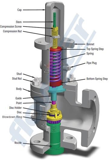
There are three main parts to the safety valve: nozzle, disc, and spring. Pressurized steam enters the valve through the nozzle and is then threaded to the boiler. The disc is the lid to the nozzle, which opens or closes depending on the pressure coming from the boiler. The spring is the pressure controller.
As a boiler starts to over pressure, the nozzle will start to receive a higher pressure coming from the inlet side of the valve, and will start to sound like it is simmering. When the pressure becomes higher than the predetermined pressure of the spring, the disc will start to lift and release the steam, creating a “pop” sound. After it has released and the steam and pressure drops below the set pressure of the valve, the spring will close the disc. Once the safety valve has popped, it is important to check the valve to make sure it is not damaged and is working properly.
A safety valve is usually referred to as the last line of safety defense. Without safety valves, the boiler can exceed it’s maximum allowable working pressure (MAWP) and not only damage equipment, but also injure or kill plant operators that are close by. Many variables can cause a safety valve on a boiler to lift, such as a compressed air or electrical power failure to control instrumentation, or an imbalance of feedwater rate caused by an inadvertently shut or open isolation valve.
Once a safety valve has lifted, it is important to do a complete boiler inspection and confirm that there are no other boiler servicing issues. A safety valve should only do its job once; safety valves should not lift continuously. Lastly, it is important to have the safety valves fully repaired, cleaned and recertified with a National Board valve repair (VR) stamp as required by local code or jurisdiction. Safety valves are a critical component in a steam system, and must be maintained.
All of Nationwide Boiler’s rental boilers include on to two safety valves depending on the size; one set at design pressure and the other set slightly higher than design. By request, we can reset the safeties to a lower pressure if the application requires it. In addition, the valves are thoroughly checked after every rental and before going out to a new customer, and they are replaced and re-certified as needed.

Safety valves or pressure relief valves are pressure regulating devices that are responsible for expelling excess pressure from the system when the maximum pressure levels for which they have been designed are exceeded, usually due to a
Safety valves perform their function when the pressure of the system where the fluid is contained, becomes higher than the maximum set pressure of the valve previously adjusted. When the system pressure is higher than the valve’s set
pressure, this opens, releasing the excess pressure to the atmosphere or to containment tanks, depending on the toxicity of the fluid. After releasing the excess, the valve closes again and the system pressure returns to normal.
To ensure total safety of personnel and installation, make sure that the valves have passed all safety tests and meet the requirements of the system where they are to be installed. All our valves are supplied with certificates of materials, cas-
What is the difference between the instantaneous full opening safety valve AIT (PSV) and the normal opening relief valve AN or progressive opening relief valve AP (PRV)?
The Pressure Safety Valve (PSV) opens instantaneously and fully upon reaching the set pressure for which it is designed, expelling the excess pressure from the system immediately. They are optimised for use with steam or gases.
In contrast, the normally or progressively opening Pressure Relief Valve (PRV) opens gradually as the system pressure rises above the set pressure of the valve above its setting. They are optimised to work with liquids.
At VYC Industrial we are specialists in the design and manufacture of all types of safety valves. We have a wide range of safety valves to cover all the needs of the sector.
The Mod. 496 EN safety valve works as an automatic pressure releasing regulator activated by the static pressure existing at the entrance to the valve and is characterized by its ability to open instantly and totally.
The Mod. 495 EN pressure relief valve works as an automatic pressure releasing regulator activated by the static pressure existing at the entrance to the valve and is characterized by its ability to open instantly and totally.
The relief valve works as an automatic pressure releasing regulator activated by the static pressure existing at the entrance to the valve and is characterized by its ability to open instantly and totally.
The valve works as an automatic pressure releasing regulator activated by the static pressure existing at the entrance to the valve and is characterized by its ability to open instantly and totally.
The valve works as an automatic pressure releasing regulator activated by the static pressure existing at the entrance to the valve and is characterized by its ability to open instantly and totally.
The valve works as an automatic pressure releasing regulator activated by the static pressure existing at the entrance to the valve and is characterized by its ability to open instantly and totally.
The valve works as an automatic pressure releasing regulator activated by the static pressure existing at the entrance to the valve and is characterized by its ability to open instantly and totally.
The valve works as an automatic pressure releasing regulator activated by the static pressure existing at the entrance to the valve and is characterized by its ability to open instantly and totally.
The valve works as an automatic pressure releasing regulator activated by the static pressure existing at the entrance to the valve and is characterized by its ability to open, at the fi rst proportional to the pressure increase, and after instantly and totally.
The valve works as an automatic pressure releasing regulator activated by the static pressure existing at the entrance to the valve and is characterized by its ability to open, at the fi rst proportional to the pressure increase, and after instantly and totally.
The valve works as an automatic pressure releasing regulator activated by the static pressure existing at the entrance to the valve and is characterized by its ability to open, at the fi rst proportional to the pressure increase, and after instantly and totally.
The valve works as an automatic pressure releasing regulator activated by the static pressure existing at the entrance to the valve and is characterized by its ability to open proportional to the pressure increase.
The valve works as an automatic pressure releasing regulator activated by the static pressure existing at the entrance to the valve and is characterized by its ability to open proportional to the pressure increase.
The valve works as an automatic pressure releasing regulator activated by the static pressure existing at the entrance to the valve and is characterized by its ability to open instantly and totally.
The valve works as an automatic pressure releasing regulator activated by the static pressure existing at the entrance to the valve and is characterized by its ability to open instantly and totally.
The valve works as an automatic pressure releasing regulator activated by the static pressure existing at the entrance to the valve and is characterized by its ability to open instantly and totally.
The valve works as an automatic pressure releasing regulator activated by the static pressure existing at the entrance to the valve and is characterized by its ability to open instantly and totally.
The valve works as an automatic pressure releasing regulator activated by the static pressure existing at the entrance to the valve and is characterized by its ability to open instantly and totally.
They are used in places such as power, chemical and petrochemical plants to discharge safety valves, control valves, etc. in pressure lines and equipment that convey compressible substances such as steam, air, carbon dioxide, helium, methane, nitrogen, oxygen and other gases.
Test bench for regular inspections and setting and resetting safety valves. Ideal for distributors, maintenance companies or with in-house maintenance. It allows safety valves to be adjusted, tested and/or checked to the test pressure (setting) Pe wile cold (simulating service conditions), matching the opening pressure Ps and the closing pressure Pc, in accordance with the standard regulations.
Controlled safety pressure relief system CSPRS valves are mainly used where conventional direct-loaded spring action valves cannot guarantee the opening and closing margins that certain specifi c conditions of service demand.
The objective is to help the closure by means of pressure so that the valve remains completely watertight until reaching the set pressure and/or to activate the opening with pressure.
Once evacuated and in keeping with a previous adjustment, to assist with closing pressure, to once again achieve closure with the desired watertightness.
Increase the operating pressure of the system up to 99.9% of the set pressure.The control safety pressure relief system CSPRS device can be used with any safety valve available in the market and in particular, with models VYC Mod. 485, 486, 494, 495 and 496.


 8613371530291