
boiler safety valve testing frequency made in china

As soon as mankind was able to boil water to create steam, the necessity of the safety device became evident. As long as 2000 years ago, the Chinese were using cauldrons with hinged lids to allow (relatively) safer production of steam. At the beginning of the 14th century, chemists used conical plugs and later, compressed springs to act as safety devices on pressurised vessels.
Early in the 19th century, boiler explosions on ships and locomotives frequently resulted from faulty safety devices, which led to the development of the first safety relief valves.
In 1848, Charles Retchie invented the accumulation chamber, which increases the compression surface within the safety valve allowing it to open rapidly within a narrow overpressure margin.
Today, most steam users are compelled by local health and safety regulations to ensure that their plant and processes incorporate safety devices and precautions, which ensure that dangerous conditions are prevented.
The principle type of device used to prevent overpressure in plant is the safety or safety relief valve. The safety valve operates by releasing a volume of fluid from within the plant when a predetermined maximum pressure is reached, thereby reducing the excess pressure in a safe manner. As the safety valve may be the only remaining device to prevent catastrophic failure under overpressure conditions, it is important that any such device is capable of operating at all times and under all possible conditions.
Safety valves should be installed wherever the maximum allowable working pressure (MAWP) of a system or pressure-containing vessel is likely to be exceeded. In steam systems, safety valves are typically used for boiler overpressure protection and other applications such as downstream of pressure reducing controls. Although their primary role is for safety, safety valves are also used in process operations to prevent product damage due to excess pressure. Pressure excess can be generated in a number of different situations, including:
The terms ‘safety valve’ and ‘safety relief valve’ are generic terms to describe many varieties of pressure relief devices that are designed to prevent excessive internal fluid pressure build-up. A wide range of different valves is available for many different applications and performance criteria.
In most national standards, specific definitions are given for the terms associated with safety and safety relief valves. There are several notable differences between the terminology used in the USA and Europe. One of the most important differences is that a valve referred to as a ‘safety valve’ in Europe is referred to as a ‘safety relief valve’ or ‘pressure relief valve’ in the USA. In addition, the term ‘safety valve’ in the USA generally refers specifically to the full-lift type of safety valve used in Europe.
Pressure relief valve- A spring-loaded pressure relief valve which is designed to open to relieve excess pressure and to reclose and prevent the further flow of fluid after normal conditions have been restored. It is characterised by a rapid-opening ‘pop’ action or by opening in a manner generally proportional to the increase in pressure over the opening pressure. It may be used for either compressible or incompressible fluids, depending on design, adjustment, or application.
Safety valves are primarily used with compressible gases and in particular for steam and air services. However, they can also be used for process type applications where they may be needed to protect the plant or to prevent spoilage of the product being processed.
Relief valve - A pressure relief device actuated by inlet static pressure having a gradual lift generally proportional to the increase in pressure over opening pressure.
Relief valves are commonly used in liquid systems, especially for lower capacities and thermal expansion duty. They can also be used on pumped systems as pressure overspill devices.
Safety relief valve - A pressure relief valve characterised by rapid opening or pop action, or by opening in proportion to the increase in pressure over the opening pressure, depending on the application, and which may be used either for liquid or compressible fluid.
In general, the safety relief valve will perform as a safety valve when used in a compressible gas system, but it will open in proportion to the overpressure when used in liquid systems, as would a relief valve.
Safety valve- A valve which automatically, without the assistance of any energy other than that of the fluid concerned, discharges a quantity of the fluid so as to prevent a predetermined safe pressure being exceeded, and which is designed to re-close and prevent further flow of fluid after normal pressure conditions of service have been restored.
There are various safety valves available to meet various applications and performance criteria demanded by various industries. Furthermore, national standards determine many types of varied safety valves.
Standard ASME I and ASME VIII standards for boiler applications and vessels and ASME / ANSI PTC 25.3 standards for safety valves and relief valves provide the following definition. These standards set performance characteristics and define various types of safety valves used:
ASME I valve - A safety relief valve conforming to the requirements of Section I of the ASME pressure vessel code for boiler applications which will open within 3% overpressure and close within 4%. It will usually feature two blowdown rings and is identified by a National Board ‘V’ stamp.
ASME VIII valve - A safety relief valve conforming to the requirements of Section VIII of the ASME pressure vessel code for pressure vessel applications which will open within 10% overpressure and close within 7%. Identified by a National Board ‘UV’ stamp.
Full bore safety valve - A safety valve having no protrusions in the bore, and wherein the valve lifts to an extent sufficient for the minimum area at any section, at or below the seat, to become the controlling orifice.
Conventional safety relief valve - The spring housing is vented to the discharge side, hence operational characteristics are directly affected by changes in the backpressure to the valve.
Balanced safety relief valve - A balanced valve incorporates a means of minimizing the effect of backpressure on the operational characteristics of the valve.
Pilot operated pressure relief valve - The major relieving device is combined with, and is controlled by, a self-actuated auxiliary pressure relief device.
Power-actuated safety relief valve - A pressure relief valve in which the major pressure-relieving device is combined with, and controlled by, a device requiring an external source of energy.
Standard safety valve - A valve which, following the opening, reaches the degree of lift necessary for the mass flowrate to be discharged within a pressure rise of not more than 10%. (The valve is characterized by a pop-type action and is sometimes known as high lift).
Full lift (Vollhub) safety valve - A safety valve which, after commencement of lift, opens rapidly within a 5% pressure rise up to the full lift as limited by the design. The amount of lift up to the rapid opening (proportional range) shall not be more than 20%.
Directly loaded safety valve - A safety valve in which the opening force underneath the valve disc is opposed by a closing force such as a spring or a weight.
Proportional safety valve - A safety valve that opens more or less steadily in relation to the increase in pressure. Sudden opening within a 10% lift range will not occur without a pressure increase. Following opening within a pressure of not more than 10%, these safety valves achieve the lift necessary for the mass flow to be discharged.
Diaphragm safety valve - A directly loaded safety valve wherein linear moving and rotating elements and springs are protected against the effects of the fluid by a diaphragm
Bellows safety valve - A directly loaded safety valve wherein sliding and (partially or fully) rotating elements and springs are protected against the effects of the fluids by a bellows. The bellows may be of such a design that it compensates for influences of backpressure.
Controlled safety valve- Consists of the main valve and a control device. It also includes direct acting safety valves with supplementary loading in which, until the set pressure is reached, an additional force increases the closing force.
Safety valve - A safety valve which automatically, without the assistance of any energy other than that of the fluid concerned, discharges a quantity of the fluid so as to prevent a predetermined safe pressure from being exceeded, and which is designed to re-close and prevent further flow of fluid after normal pressure conditions of service have been restored. Note; the valve can be characterized either by pop action (rapid opening) or by opening in proportion (not necessarily linear) to the increase in pressure over the set pressure.
Directly loaded safety valve - A safety valve in which the loading due to the fluid pressure underneath the valve disc is opposed only by a direct mechanical loading device such as weight, lever, and weight, or a spring.
Assisted safety valve - A safety valve which by means of a powered assistance mechanism, may additionally be lifted at a pressure lower than the set pressure and will, even in the event of a failure of the assistance mechanism, comply with all the requirements for safety valves given in the standard.
Supplementary loaded safety valve - A safety valve that has, until the pressure at the inlet to the safety valve reaches the set pressure, an additional force, which increases the sealing force.
Notes; This additional strength (additional burden), which can be provided through foreign resources, is reliably released when the pressure on the safety valve inlet reaches the specified pressure. The amount of additional loading is very regulated that if the additional loading is not released, the safety valve will reach its certified discharge capacity at a pressure which is no greater than 1.1 times the maximum pressure that is permitted to be protected.
Pilot operated safety valve - A safety valve, the operation of which is initiated and controlled by the fluid discharged from a pilot valve, which is itself, a directly loaded safety valve subject to the requirement of the standard.
The common characteristic shared between the definitions of conventional safety valves in the different standards, is that their operational characteristics are affected by any backpressure in the discharge system. It is important to note that the total backpressure is generated from two components; superimposed backpressure and the built-up backpressure:
Subsequently, in a conventional safety valve, only the superimposed backpressure will affect the opening characteristic and set value, but the combined backpressure will alter the blowdown characteristic and re-seat value.
Once the valve starts to open, the effects of built-up backpressure also have to be taken into account. For a conventional safety valve with the spring housing vented to the discharge side of the valve.
Therefore, if the back pressure is greater than the overpressure, the valve will tend to close, reducing the flow. This can lead to instability within the system and can result in flutter or chatter of the valve.
In general, if conventional safety valves are used in applications, where there is excessive built-up backpressure, they will not perform as expected. According to the API 520 Recommended Practice Guidelines:
A conventional pressure relief valve should typically not be used when the built-up backpressure is greater than 10% of the set pressure at 10% overpressure. A higher maximum allowable built-up backpressure may be used for overpressure greater than 10%.
The European Standard EN ISO 4126, however, states that the built-up backpressure should be limited to 10% of the set pressure when the valve is discharging at the certified capacity.
For the majority of steam applications, the back pressure can be maintained within these limits by carefully sizing any discharge pipes. This will be discussed in Module 9.4. If, however, it is not feasible to reduce the backpressure, then it may be necessary to use a balanced safety valve.
Balanced safety valves are those that incorporate a means of eliminating the effects of backpressure. There are two basic designs that can be used to achieve this:
The bellows arrangement prevents back pressure acting on the upper side of the disc within the area of the bellows. The disc area extending beyond the bellows and the opposing disc area are equal, and so the forces acting on the disc are balanced, and the backpressure has little effect on the valve opening pressure.
Bellows failure is an important concern when using a bellows balanced safety valve, as this may affect the set pressure and capacity of the valve. It is important, therefore, that there is some mechanism for detecting any uncharacteristic fluid flow through the bellows vents. In addition, some bellows balanced safety valves include an auxiliary piston that is used to overcome the effects of backpressure in the case of bellows failure. This type of safety valve is usually only used on critical applications in the oil and petrochemical industries.
Since balanced pressure relief valves are typically more expensive than their unbalanced counterparts, they are commonly only used where high-pressure manifolds are unavoidable, or in critical applications where a very precise set pressure or blowdown is required.
This type of safety valve uses the flowing medium itself, through a pilot valve, to apply the closing force on the safety valve disc. The pilot valve is itself a small safety valve.
The diaphragm type is typically only available for low-pressure applications and it produces a proportional type action, characteristic of relief valves used in liquid systems. They are therefore of little use in steam systems, consequently, they will not be considered in this text.
The piston-type valve consists of the main valve, which uses a piston-shaped closing device (or obturator), and an external pilot valve. Below photo shows a diagram of a typical piston type, pilot-operated safety valve.
The piston and seating arrangement incorporated in the main valve is designed so that the bottom area of the piston, exposed to the inlet fluid, is less than the area of the top of the piston. As both ends of the piston are exposed to the fluid at the same pressure, this means that under normal system operating conditions, the closing force, resulting from the larger top area, is greater than the inlet force. The resultant downward force therefore holds the piston firmly on its seat.
If the inlet pressure were to rise, the net closing force on the piston also increases, ensuring that a tight shut-off is continually maintained. However, when the inlet pressure reaches the set pressure, the pilot valve will pop open to release the fluid pressure above the piston. With much less fluid pressure acting on the upper surface of the piston, the inlet pressure generates a net upwards force and the piston will leave its seat. This causes the main valve to pop open, allowing the process fluid to be discharged.
When the inlet pressure has been sufficiently reduced, the pilot valve will reclose, preventing the further release of fluid from the top of the piston, thereby re-establishing the net downward force, and causing the piston to reseat.
Pilot operated safety valves offer good overpressure and blowdown performance (a blowdown of 2% is attainable). For this reason, they are used where a narrow margin is required between the set pressure and the system operating pressure. Pilot operated valves are also available in much larger sizes, making them the preferred type of safety valve for larger capacities.
One of the main concerns with pilot operated safety valves is that the small bore, pilot connecting pipes are susceptible to blockage by foreign matter, or due to the collection of condensate in these pipes. This can lead to the failure of the valve, either in the open or closed position, depending on where the blockage occurs.
The terms full lift, high lift and low lift refer to the amount of travel the disc undergoes as it moves from its closed position to the position required to produce the certified discharge capacity, and how this affects the discharge capacity of the valve.
A full lift safety valve is one in which the disc lifts sufficiently, so that the curtain area no longer influences the discharge area. The discharge area, and therefore the capacity of the valve are subsequently determined by the bore area. This occurs when the disc lifts a distance of at least a quarter of the bore diameter. A full lift conventional safety valve is often the best choice for general steam applications.
The disc of a high lift safety valve lifts a distance of at least 1/12th of the bore diameter. This means that the curtain area, and ultimately the position of the disc, determines the discharge area. The discharge capacities of high lift valves tend to be significantly lower than those of full lift valves, and for a given discharge capacity, it is usually possible to select a full lift valve that has a nominal size several times smaller than a corresponding high lift valve, which usually incurs cost advantages.Furthermore, high lift valves tend to be used on compressible fluids where their action is more proportional.
In low lift valves, the disc only lifts a distance of 1/24th of the bore diameter. The discharge area is determined entirely by the position of the disc, and since the disc only lifts a small amount, the capacities tend to be much lower than those of full or high lift valves.
Except when safety valves are discharging, the only parts that are wetted by the process fluid are the inlet tract (nozzle) and the disc. Since safety valves operate infrequently under normal conditions, all other components can be manufactured from standard materials for most applications. There are however several exceptions, in which case, special materials have to be used, these include:
Cast steel - Commonly used on higher pressure valves (up to 40 bar g). Process type valves are usually made from a cast steel body with an austenitic full nozzle type construction.
For all safety valves, it is important that moving parts, particularly the spindle and guides are made from materials that will not easily degrade or corrode. As seats and discs are constantly in contact with the process fluid, they must be able to resist the effects of erosion and corrosion.
The spring is a critical element of the safety valve and must provide reliable performance within the required parameters. Standard safety valves will typically use carbon steel for moderate temperatures. Tungsten steel is used for higher temperature, non-corrosive applications, and stainless steel is used for corrosive or clean steam duty. For sour gas and high temperature applications, often special materials such as monel, hastelloy and ‘inconel’ are used.
Standard safety valves are generally fitted with an easing lever, which enables the valve to be lifted manually in order to ensure that it is operational at pressures in excess of 75% of set pressure. This is usually done as part of routine safety checks, or during maintenance to prevent seizing. The fitting of a lever is usually a requirement of national standards and insurance companies for steam and hot water applications. For example, the ASME Boiler and Pressure Vessel Code states that pressure relief valves must be fitted with a lever if they are to be used on air, water over 60°C, and steam.
A test gag (Figure 9.2.7) may be used to prevent the valve from opening at the set pressure during hydraulic testing when commissioning a system. Once tested, the gag screw is removed and replaced with a short blanking plug before the valve is placed in service.
The amount of fluid depends on the particular design of the safety valve. If the emission of this fluid into the atmosphere is acceptable, the spring housing may be vented to the atmosphere – an open bonnet. This is usually advantageous when the safety valve is used on high-temperature fluids or for boiler applications as, otherwise, high temperatures can relax the spring, altering the set pressure of the valve. However, using an open bonnet exposes the valve spring and internals to environmental conditions, which can lead to damage and corrosion of the spring.
When the fluid must be completely contained by the safety valve (and the discharge system), it is necessary to use a closed bonnet, which is not vented to the atmosphere. This type of spring enclosure is almost universally used for small screwed valves and, it is becoming increasingly common on many valve ranges since, particularly on steam, discharge of the fluid could be hazardous to personnel.
Some safety valves, most commonly those used for water applications, incorporate a flexible diaphragm or bellows to isolate the safety valve spring and upper chamber from the process fluid, (see Figure 9.2.9).

Safety valves are an arrangement or mechanism to release a substance from the concerned system in the event of pressure or temperature exceeding a particular preset limit. The systems in the context may be boilers, steam boilers, pressure vessels or other related systems. As per the mechanical arrangement, this one get fitted into the bigger picture (part of the bigger arrangement) called as PSV or PRV that is pressure safety or pressure relief valves.
This type of safety mechanism was largely implemented to counter the problem of accidental explosion of steam boilers. Initiated in the working of a steam digester, there were many methodologies that were then accommodated during the phase of the industrial revolution. And since then this safety mechanism has come a long way and now accommodates various other aspects.
These aspects like applications, performance criteria, ranges, nation based standards (countries like United States, European Union, Japan, South Korea provide different standards) etc. manage to differentiate or categorize this safety valve segment. So, there can be many different ways in which these safety valves get differentiated but a common range of bifurcation is as follows:
The American Society of Mechanical Engineers (ASME) I tap is a type of safety valve which opens with respect to 3% and 4% of pressure (ASME code for pressure vessel applications) while ASME VIII valve opens at 10% over pressure and closes at 7%. Lift safety valves get further classified as low-lift and full lift. The flow control valves regulate the pressure or flow of a fluid whereas a balanced valve is used to minimize the effects induced by pressure on operating characteristics of the valve in context.
A power operated valve is a type of pressure relief valve is which an external power source is also used to relieve the pressure. A proportional-relief valve gets opened in a relatively stable manner as compared to increasing pressure. There are 2 types of direct-loaded safety valves, first being diaphragms and second: bellows. diaphragms are valves which spring for the protection of effects of the liquid membrane while bellows provide an arrangement where the parts of rotating elements and sources get protected from the effects of the liquid via bellows.
In a master valve, the operation and even the initiation is controlled by the fluid which gets discharged via a pilot valve. Now coming to the bigger picture, the pressure safety valves based segment gets classified as follows:
So all in all, pressure safety valves, pressure relief valves, relief valves, pilot-operated relief valves, low pressure safety valves, vacuum pressure safety valves etc. complete the range of safety measures in boilers and related devices.
Safety valves have different discharge capacities. These capacities are based on the geometrical area of the body seat upstream and downstream of the valve. Flow diameter is the minimum geometrical diameter upstream and downstream of the body seat.
The nominal size designation refers to the inlet orifice diameter. A safety Valve"s theoretical flowing capacity is the mass flow through an orifice with the same cross-sectional area as the valve"s flow area. This capacity does not account for the flow losses caused by the valve. The actual capacity is measured, and the certified flow capacity is the actual flow capacity reduced by 10%.
A safety valve"s discharge capacity is dependent on the set pressure and position in a system. Once the set pressure is calculated, the discharge capacity must be determined. Safety valves may be oversized or undersized depending on the flow throughput and/or the valve"s set pressure.
The actual discharge capacity of a safety valve depends on the type of discharge system used. In liquid service, safety valves are generally automatic and direct-pressure actuated.
A safety valve is used to protect against overpressure in a fluid system. Its design allows for a lift in the disc, indicating that the valve is about to open. When the inlet pressure rises above the set pressure, the guide moves to the open position, and media flows to the outlet via the pilot tube. Once the inlet pressure falls below the set pressure, the main valve closes and prevents overpressure. There are five criteria for selecting a safety valve.
The first and most basic requirement of a safety valve is its ability to safely control the flow of gas. Hence, the valve must be able to control the flow of gas and water. The valve should be able to withstand the high pressures of the system. This is because the gas or steam coming from the boiler will be condensed and fill the pipe. The steam will then wet the safety valve seat.
The other major requirement for safety valves is their ability to prevent pressure buildup. They prevent overpressure conditions by allowing liquid or gas to escape. Safety valves are used in many different applications. Gas and steam lines, for example, can prevent catastrophic damage to the plant. They are also known as safety relief valves. During an emergency, a safety valve will open automatically and discharge gas or liquid pressure from a pressurized system, preventing it from reaching dangerous levels.
The discharge capacity of a safety valve is based on its orifice area, set pressure, and position in the system. A safety valve"s discharge capacity should be calculated based on the maximum flow through its inlet and outlet orifice areas. Its nominal size is often determined by manufacturer specifications.
Its discharge capacity is the maximum flow through the valve that it can relieve, based on the maximum flow through each individual flow path or combined flow path. The discharge pressure of the safety valve should be more than the operating pressure of the system. As a thumb rule, the relief pressure should be 10% above the working pressure of the system.
It is important to choose the discharge capacity of a safety valve based on the inlet and output piping sizes. Ideally, the discharge capacity should be equal to or greater than the maximum output of the system. A safety valve should also be installed vertically and into a clean fitting. While installing a valve, it is important to use a proper wrench for installation. The discharge piping should slope downward to drain any condensate.
The discharge capacity of a safety valve is measured in a few different ways. The first is the test pressure. This gauge pressure is the pressure at which the valve opens, while the second is the pressure at which it re-closes. Both are measured in a test stand under controlled conditions. A safety valve with a test pressure of 10,000 psi is rated at 10,000 psi (as per ASME PTC25.3).
The discharge capacity of a safety valve should be large enough to dissipate a large volume of pressure. A small valve may be adequate for a smaller system, but a larger one could cause an explosion. In a large-scale manufacturing plant, safety valves are critical for the safety of personnel and equipment. Choosing the right valve size for a particular system is essential to its efficiency.
Before you use a safety valve, you need to know its discharge capacity. Here are some steps you need to follow to calculate the discharge capacity of a safety valve.
To check the discharge capacity of a safety valve, the safety valve should be installed in the appropriate location. Its inlet and outlet pipework should be thoroughly cleaned before installation. It is important to avoid excessive use of PTFE tape and to ensure that the installation is solid. The safety valve should not be exposed to vibration or undue stress. When mounting a safety valve, it should be installed vertically and with the test lever at the top. The inlet connection of the safety valve should be attached to the vessel or pipeline with the shortest length of pipe. It must not be interrupted by any isolation valve. The pressure loss at the inlet of a safety valve should not exceed 3% of the set pressure.
The sizing of a safety valve depends on the amount of fluid it is required to control. The rated discharge capacity is a function of the safety valve"s orifice area, set pressure, and position in the system. Using the manufacturer"s specifications for orifice area and nominal size of the valve, the capacity of a safety valve can be determined. The discharge flow can be calculated using the maximum flow through the valve or the combined flows of several paths. When sizing a safety valve, it"s necessary to consider both its theoretical and actual discharge capacity. Ideally, the discharge capacity will be equal to the minimum area.
To determine the correct set pressure for a safety valve, consider the following criteria. It must be less than the MAAP of the system. Set pressure of 5% greater than the MAAP will result in an overpressure of 10%. If the set pressure is higher than the MAAP, the safety valve will not close. The MAAP must never exceed the set pressure. A set pressure that is too high will result in a poor shutoff after discharge. Depending on the type of valve, a backpressure variation of 10% to 15% of the set pressure cannot be handled by a conventional valve.
Manufacturers outside China, who have difficulties to completely carry out the above-mentioned regulations, are allowed to adopt the technical codes and standards, which is conventional and complete in system and are used by most countries after having approved by Boiler and Pressure Vessel Safety Supervision Administration of AQSIQ. But, in this case, they must meet the requirement as stipulated from article 45 to 50 onwards simultaneously.
Steel for pressure components of the boiler (including staying components) must be killed-steels. The designations of the steel should be those listed in foreign boiler steel standards, or of conventional boiler steels.
The results of visual inspection of boiler, mechanical property testing of welded joint, metallograpy and fractography, hydrostatic pressure test, and the NDE items and detective rate must satisfy the requirements of above-mentioned Chinese boiler codes and regulations.
4. Two independent water-level gauges should be mounted on the drum of every steam boiler. Only one gauge may be mounted if one of the following conditions is met:
5. For boilers with a rated capacity not less than 2 t/h, the low/high water level alarms and low water level interlock-protection device should be provided. For boilers with rated capacity not less than 6 t/h, the over-pressure alarm and the over-pressure interlock device should be provided.
7. For hot water boilers with rated temperature of outlet water not less than 120 °C or with rated heating capacity not less than 4.2 MW, the over-temperature alarm should be provided.
2. Strength Calculation sheets for pressure components and the calculation sheets for relieving capacity of safety valves (or selected from operational manual of the safety valves) or a summary of above mentioned calculation results.
A metallic nameplate should be put on the conspicuous place on the boiler. The contents on the nameplate should include at least the following items (in Chinese or English and using SI units):
Pressure vessels produced by pressure vessel manufacturers should meet the requirements of the following Chinese pressure vessels" safety technical codes and regulations:
Manufacturers outside China, who have difficulties to completely carry out the above-mentioned regulations, are allowed to adopt the technical codes and standards, which is conventional and complete in system and are used by most countries after having approved by safety supervision administration under AQSIQ. But, in this case, they must meet the requirement as stipulated from article 52 to 58 onwards simultaneously.
3. Calculation sheets for the required safe relieving capacity of pressure vessel, relieving capacity of safety valves and/or the discharge area of bursting or a summary of above calculation results.
In general, the safety factor for steel pressure vessel shall not be less than 3 if the design is based on the tensile strength at ambient temperature. The factors should normally not less than 1.6 for carbon steel and low alloy steel and not less than 1.5 for high alloy steel if the design is based on the yield strength at ambient temperature. Otherwise, it should subject to prior approval by the safety supervision administration of AQSIQ.
The safety factor for stress analyzing design should normally not be l;ess than 2.6 if the design is based on the tensile strength at ambient temperature and should normally not be less than 1.5 if the design is based on the yield strength both at ambient and design temperatures. Otherwise, it should subject to prior approval by the safety supervision administration of AQSIQ.
3. If the pressure vessel is designed by the strength calculation method other than those in the relevant standards or designed by proof testing, the manufacturer should register at the safety supervision administration of AQSIQ.
c. The words by other means having the same quality as full penetrating double welding in the Table means the welded joint welding by one side which can assure good weld appearance at both side. In this case, it should be qualified with the same measures as for welding by both sides (including the qualification of welding testing plate). The welds by using argon shielded arc welding in backing welding or using ceramic or copper backing pads are the examples.
3). Weldablity test report and welding procedure qualification report of the material should be provided, and report safety supervision administration of AQSIQ for review and approval.
minimum tensile strength in the relevant standard is equal to or greater than 540MPa, the phosphor and sulfur contents shall not be greater than 0.020% and 0.015% respectively. The welding cracking sensitivity coefficient Pcm shall not be greater than 0.25%, and the weldablity test report and welding procedure qualification report of the material shall be provided to safety supervision administration of AQSIQ for review and approval.
1. All gas cylinders must be designed and manufactured in accordance with the Chinese national standards. In addition, the design documents of them shall be appraised before type testing. In the case of lack of Chinese standards, the manufacturer should report the applied standard and related technical document to the safety supervision administration of AQSIQ for review and approval. Among them, the key items related to the safety quality of gas cylinder, such as, design temperature, design pressure, bursting testing, NDE, mechanical properties, must not lower than the requirements as specified in the corresponding Chinese national standard.

Safety is of the utmost importance when dealing with pressure relief valves. The valve is designed to limit system pressure, and it is critical that they remain in working order to prevent an explosion. Explosions have caused far too much damage in companies over the years, and though pressurized tanks and vessels are equipped with pressure relief vales to enhance safety, they can fail and result in disaster.
That’s also why knowing the correct way to test the valves is important. Ongoing maintenance and periodic testing of pressurized tanks and vessels and their pressure relief valves keeps them in working order and keep employees and their work environments safe. Pressure relief valves must be in good condition in order to automatically lower tank and vessel pressure; working valves open slowly when the pressure gets high enough to exceed the pressure threshold and then closes slowly until the unit reaches the low, safe threshold. To ensure the pressure relief valve is in good working condition, employees must follow best practices for testing them including:
If you consider testing pressure relief valves a maintenance task, you’ll be more likely to carry out regular testing and ensure the safety of your organization and the longevity of your
It’s important to note, however, that the American Society of Mechanical Engineers (ASME) and National Board Inspection Code (NBIC), as well as state and local jurisdictions, may set requirements for testing frequency. Companies are responsible for checking with these organizations to become familiar with the testing requirements. Consider the following NBIC recommendations on the frequency for testing relief valves:
High-pressure steam boilers greater than 15 psi and less than 400 psi – perform manual check every six months and pressure test annually to verify nameplate set pressure
High-pressure steam boilers 400 psi and greater – pressure test to verify nameplate set pressure every three years or as determined by operating experience as verified by testing history
High-temperature hot water boilers (greater than 160 psi and/or 250 degrees Fahrenheit) – pressure test annually to verify nameplate set pressure. For safety reasons, removal and testing on a test bench is recommended
When testing the pressure relief valve, raise and lower the test lever several times. The lever will come away from the brass stem and allow hot water to come out of the end of the drainpipe. The water should flow through the pipe, and then you should turn down the pressure to stop the leak, replace the lever, and then increase the pressure.
One of the most common problems you can address with regular testing is the buildup of mineral salt, rust, and corrosion. When buildup occurs, the valve will become non-operational; the result can be an explosion. Regular testing helps you discover these issues sooner so you can combat them and keep your boiler and valve functioning properly. If no water flows through the pipe, or if there is a trickle instead of a rush of water, look for debris that is preventing the valve from seating properly. You may be able to operate the test lever a few times to correct the issue. You will need to replace the valve if this test fails.
When testing relief valves, keep in mind that they have two basic functions. First, they will pop off when the pressure exceeds its safety threshold. The valve will pop off and open to exhaust the excess pressure until the tank’s pressure decreases to reach the set minimum pressure. After this blowdown process occurs, the valve should reset and automatically close. One important testing safety measure is to use a pressure indicator with a full-scale range higher than the pop-off pressure.
Thus, you need to be aware of the pop-off pressure point of whatever tank or vessel you test. You always should remain within the pressure limits of the test stand and ensure the test stand is assembled properly and proof pressure tested. Then, take steps to ensure the escaping pressure from the valve is directed away from the operator and that everyone involved in the test uses safety shields and wears safety eye protection.
After discharge – Because pressure relief valves are designed to open automatically to relieve pressure in your system and then close, they may be able to open and close multiple times during normal operation and testing. However, when a valve opens, debris may get into the valve seat and prevent the valve from closing properly. After discharge, check the valve for leakage. If the leakage exceeds the original settings, you need to repair the valve.
According to local jurisdictional requirements – Regulations are in place for various locations and industries that stipulate how long valves may operate before needing to be repair or replaced. State inspectors may require valves to be disassembled, inspected, repaired, and tested every five years, for instance. If you have smaller valves and applications, you can test the valve by lifting the test lever. However, you should do this approximately once a year. It’s important to note that ASME UG136A Section 3 requires valves to have a minimum of 75% operating pressure versus the set pressure of the valve for hand lifting to be performed for these types of tests.
Depending on their service and application– The service and application of a valve affect its lifespan. Valves used for clean service like steam typically last at least 20 years if they are not operated too close to the set point and are part of a preventive maintenance program. Conversely, valves used for services such as acid service, those that are operated too close to the set point, and those exposed to dirt or debris need to be replaced more often.
Pressure relief valves serve a critical role in protecting organizations and employees from explosions. Knowing how and when to test and repair or replace them is essential.

When I teach my steam classes, I ask the attendees, "Do you test the pop safety valve?" Most do not. When I ask why, they tell me the same reason; the safety valve will leak. I joke during the classes that you do not want to test the pop safety valve on a Friday afternoon because it will almost certainly leak. I then ask, Do you check the low water cutoff? They look at me like I have a third eye and say they always check the low water cutoff. If you test the low water cutoff, you should test the pop safety valve. It is the last line of defense against a potential catastrophe. One of the things I do when performing a boiler service call is to explain the duty of the pop safety valve and ask the customer if they would like to have it tested. I explain that it could leak and if they refuse to test it, I will notate it on my service call in case something happens. In this way, my company is protected.
The best way to understand the pop safety valve is to read the instructions which came with the valve. I don"t have a life, and while you are watching the Masked Singer, I read O & M manuals. I know, I"m weird. I figure it"s my job to share things I find while reading these page-turners. The manufacturer hides all sorts of useful tidbits on the installation and maintenance of their valve. I have enclosed some information I gleaned while reading the instructions for a Conbraco/Apollo pop safety valve.
The valve must be mounted in a vertical, upright position directly to a clean, tapped opening in the top of the boiler. I see many safety valves installed horizontally and wonder if that voids the warranty. There should be no restrictions or valves in the piping to or from the safety valve. The installation instructions require the discharge piping to be schedule 40 pipe. They specifically say not to use schedule 80 pipe, which is 50% thicker than schedule 40 pipe. Many installers use copper tubing for the discharge, which does not meet the instructions. The other thing which confuses me the manufacturer instructs you not to use a pipe wrench to install the safety valve. I would wager 99% of all valves are installed using a pipe wrench. I wonder what kind of valve they want you to use.
I consult the pop safety manufacturer or the building insurance company to determine the frequency of tests. Apollo recommends quarterly testing using the Try Lever Test unless the valve is located in a severe service condition, and then it should be done more often. They further state the pop safety valve should have a Pressure Test annually before the heating season or at the end of any non-service period. This test will check your courage as you have to jump out the pressure controls and watch the operation of the boiler as the pressure builds. If the pop safety valve opens at the set pressure, the valve is working properly. This is not a test a novice should do alone.
Apollo suggests checking the pop safety valve at or near the maximum operating pressure by holding the test lever fully open for at least 5 seconds and letting it pop closed. On a low-pressure steam system, the pop safety valve is set for 15 psi. I like to run the boiler steam pressure up to 12 psi or higher to check the pop safety valve. After the test, I drop it to the operating pressure the owner requires. If the valve does not open, the boiler should be shut down until it is checked by a licensed contractor or qualified service person.
The pop safety manufacturer requires a minimum pressure differential of five psi between the pressure relief valve set pressure and the boiler operating pressure. It further states, Under no circumstances should the margin be less than five psig. On a low-pressure steam boiler, the pop safety valve will be set for 15 psi. That means the boiler steam pressure should be ten psi or lower. In breweries, it is common to see the boiler pressure set at 12-14 psi. This is less than the five psi differential and could create a dangerous condition.

Throughout the years, HZVALVE has developed its Quality System which is an integral part of our manufacturing policy. Our primary goal is to provide products that meet and exceed market standards. In this sense, HZVALVE is an ISO-9001 Audited and Certified Company that has achieved major certifications worldwide. Our system consists of a rigorous quality control as well as the selection of raw materials from approved vendors. Control over our manufacturing process is vital. Serial numbers allow HZVALVE to monitor and trace fabrication processes along with the materials of components.
HZVALVE owned independent quality department with over 25 experienced inspectors. Our target is to cover all vital point including material, procession, assembling, testing and package for overall quality controlling and supervision. We keep the understanding that the high quality products create more value to customers.

Safety valve is a special valve that the opening and closing parts are normally closed under the action of external force. When the medium pressure in the equipment or pipeline increases beyond the specified value, the medium pressure in the pipeline or equipment is prevented from exceeding the specified value by discharging the medium outside the system. Safety valve belongs to automatic valve category, which is mainly used in boiler, pressure vessel and pipeline. The control pressure does not exceed the specified value, which plays an important role in protecting personal safety and equipment operation. Note the safety valve can only be used after pressure test.
In most cases, the safety valve is the last safety defense line. If the above safety measures fail, the safety valve will take off and release pressure to prevent the pressure in the pressure equipment from exceeding the design allowable value. Safety valve is a kind of intrinsic safety protection measure. It takes off automatically by spring force and medium force, without any manual participation and external force participation, so as to prevent the safety accident caused by human misoperation. The function of the safety valve is realized through the following action process: when the system reaches the maximum allowable pressure, the safety valve can be opened accurately, and can discharge stably with the increase of the system pressure, and can discharge the rated amount of working medium under the rated discharge pressure. When the system pressure drops to a certain value, it should be closed in time, and keep the necessary sealing under the closed state Sex.
According to the different overall structure and loading mechanism, the common types of safety valve are spring loaded safety valve, balance bellows safety valve and pilot safety valve.
Spring loaded safety valve is a common safety valve, which overcomes the force produced by the medium pressure under the valve disc by the closing force of the spring. If the medium is harmless to people and the environment, such as non-toxic, non flammable and low-cost, such as air, it can be directly discharged into the atmosphere, in this case, the ordinary safety valve is used.
Balanced bellow safety valve, the effective area of the bellow is equal to the area of the sealing surface of the valve seat, which is used to counteract the effect of back pressure on the set pressure. It is suitable for the working conditions of high temperature and pressure, high back pressure or the medium can not be directly discharged into the atmosphere.
The pilot type safety valve is usually composed of a main valve with a movable unbalanced disc and an external pilot valve (piston). It drives or controls the opening and closing of the main valve by means of the medium discharged from the pilot valve. Compared with the balanced bellows type safety valve, its back pressure compensation coefficient is higher, which reduces the influence of back pressure on the action characteristics to a minimum and the discharge volume is large. For example, in the process of overpressure, the discharge of medium in the reactor is very large. If the balance bellows type safety valve is used, 16 sets are needed at most. If the pilot type safety valve is selected, 8 sets are enough, or even less. It will bring many advantages to users, such as less installation, less maintenance, less work and convenient maintenance. Of course, the technical complexity of the pilot safety valve is high, which puts forward higher requirements for the technical level of operators.
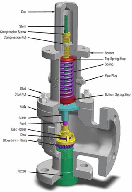
In the load spring safety valve, the valve closing pressure or spring force is applied by the coil spring under the pressure of the adjusting screw. The spring force is transferred to the disc through the stem. As long as the spring force is greater than the force generated at the inlet of the safety valve, the valve disc will seal the nozzle. The following figure shows the expanded nozzle and disc area of the relief valve at the pressure acting on the disc.
According to the preset conditions, the safety valve will open at the preset pressure. The spring force FS is applied in the closing direction, and the force FP generated by the pressure at the inlet of the safety valve is applied in the opening direction. When the pressure FS and medium force FP reach a balance, there is no force to place the valve disc on the valve seat; at this time, the safety valve will start to leak, and the sound of medium discharge can be seen or heard (the sound of medium just discharged).
Before the safety valve is obviously opened, the pressure at the valve inlet must be increased above the set pressure. Due to the flow restriction between the disc and the adjusting ring, the pressure gradually increases in this so-called mixing chamber. This pressure now acts on the expanded disc area, further increasing the pressure FP, which overcomes the additional force required to enter a compression spring. The valve will open quickly with a “bang” and in most cases it will be fully open. Overpressure refers to the pressure increase beyond the necessary set pressure of the safety valve to achieve full opening and full displacement of the valve. This overpressure is usually expressed as a percentage of the set pressure. The value is usually 10%, between 3% and 21% according to relevant specifications and applications.
In most applications, the proper size of safety valve will reduce the pressure when the vessel is discharged. The pressure of the vessel will drop at any subsequent point in time, but not later than the end of the pre-set condition. A decrease in pressure in the vessel will reduce the pressure FP. However, at set pressure, flow still acts on the expanded disc area, which opens the valve. Further pressure reduction is required before the spring force FS exceeds FP again and the relief valve begins to close again. Moreover, under the so-called reseating pressure, the disc will contact the nozzle again and the safety valve will close again. Return pressure difference refers to the difference between the set pressure of the safety valve and the return pressure, which is calculated as a percentage of the set pressure. According to the definition of relevant codes and standards, the reseating differential pressure is generally – 7% to – 10%, and it is – 4% to – 20% according to relevant codes and services (steam, gas or liquid).
API 526 safety valve series has a down regulating ring, and its set pressure is defined as the set pressure of the valve when the pressure reaches the initial discharge sound.
It is important to understand that the operating pressure of the protected equipment should be less than the reseating pressure of the safety valve. Most manufacturers and relevant codes and standards recommend that the difference between the reseating pressure and the operating pressure of 3% – 5% can achieve reasonable adjustment of the valve seat, and can again achieve good tightness of the valve seat.
Because the area of the pressure chamber is larger than the area of the main valve seat, the closing pressure is larger than the opening pressure. This allows the main valve to close tightly.
When the pressure reaches the set pressure, the pilot relief valve is activated. The medium will no longer lead to the pressure chamber (see Figure). This prevents further pressure rise in the pressure chamber.
At the same time, the pressure of the pressure chamber is discharged. Results the closing pressure of the main valve disappeared, which provided the precondition for the system overpressure to push the main valve to open.
The main valve is open. According to the design of pilot safety valve, there are two opening modes of safety valve, one is quick and thorough (quick opening action), the other is gradual and local (regulating action).
When the pressure in the pressure chamber increases, the main valve can be closed again through quick and thorough (quick opening action) or gradual local (regulating action).
Safety valve, also known as overflow valve, is a special valve that the opening and closing parts are normally closed under the action of external force. When the medium pressure in the equipment or pipeline increases beyond the specified value, the medium pressure in the pipeline or equipment is prevented from exceeding the specified value by discharging the medium outside the system. Safety valve belongs to automatic valve category, which is mainly used in boiler, pressure vessel and pipeline. The control pressure does not exceed the specified value, which plays an important role in protecting personal safety and equipment operation. Note the safety valve can only be used after pressure test.
The figure shows several typical structures of the safety valve. Fig. A is a piston type safety valve with a flat valve core. The air source pressure acts on piston A. when the pressure exceeds the safety value determined by the spring force, piston a is jacked open and part of the compressed air is discharged into the atmosphere from the valve port; when the air source pressure is lower than the safety value, the spring drives the piston to move down and close the valve port.
Figure B and figure C are ball valve type and diaphragm type safety valves respectively, with the same working principle as piston type. These three kinds of safety valves are all spring-loaded to provide control force. Adjusting the spring preload can change the safety value, so they are called direct acting safety valves.
Fig. D is a pilot type safety valve. The small direct acting valve provides control pressure to act on the diaphragm. The hard core on the diaphragm is the valve core, which is pressed on the valve seat. When the air source pressure a is greater than the safety pressure, the valve core is opened, and the compressed air is discharged into the atmosphere from the left output hole. The pressure characteristics of the diaphragm safety valve and the pilot safety valve are good and the action is sensitive, but the maximum opening force is relatively small, that is, the flow characteristics are poor. In practical application, the type of safety valve should be selected according to the actual needs, and its diameter should be selected according to the maximum exhaust volume.
① before leaving the factory, the opening pressure of the safety valve shall be adjusted one by one to the setting value required by the user. If the user puts forward the working pressure level of the spring, it shall be adjusted according to the lower limit value of the pressure level.
② before installing the safety valve on the protected equipment or before installation, the user must readjust it on the installation site to ensure that the set pressure value of the safety valve meets the requirements.
④ before rotating the adjusting screw, the inlet pressure of the valve shall be reduced below 90% of the opening pressure to prevent the valve disc from being driven to rotate when rotating the adjusting screw, so as to damage the sealing surface.
⑤ in order to ensure the accuracy of the opening pressure value, the medium conditions during adjustment, such as medium type and temperature, shall be close to the actual operation conditions as much as possible. With the change of medium type, especially when the accumulation state of medium is different (for example, from liquid phase to gas phase), the opening pressure often changes. When the working temperature increases, the opening pressure generally decreases. Therefore, when it is adjusted at room temperature and used at high temperature, the set pressure at room temperature shall be slightly higher than the required opening pressure. The degree to which it is related to the valve structure and material selection shall be based on the manufacturer’s instructions.
⑥ when the conventional safety valve is used to fix additional back pressure, the setting value should be less than the required back pressure when the opening pressure is adjusted after testing.
① to adjust the discharge pressure and reseating pressure of the valve, the action test of the valve reaching the full opening height must be carried out. Therefore, it can only be carried out on the large capacity test device or after the safety valve is installed on the protected equipment. The adjustment method depends on the valve structure.
② for the structure with recoil plate and valve seat adjusting ring, the valve seat adjusting ring is used for adjustment. Screw out the fixing screw of the adjusting ring, extend a thin iron bar or other tools from the exposed screw hole, and then move the teeth on the adjusting ring to make the adjusting ring rotate left and right. When the adjusting ring rotates counterclockwise to the left, its position increases, and the discharge pressure and the reseating pressure decrease. On the contrary, when the adjusting ring is rotated clockwise, its position will decrease, and the discharge pressure and reseating pressure will increase. For each adjustment, the adjustment: the rotation range of the ring should not be too large (generally, the number of teeth can be turned). After each adjustment, screw on the fixing screw so that its end is located in the groove between the two teeth of the adjusting ring, which can not only prevent the adjusting ring from turning, but also do not generate radial pressure on the adjusting ring. For the sake of safety, the inlet pressure of the safety valve shall be properly reduced (generally lower than 90% of the opening pressure) before the adjusting ring is moved to prevent the valve from suddenly opening during the adjustment, causing accidents.
③ for the structure with up and down regulating rings (one regulating ring on the guide sleeve and one regulating ring on the valve seat), the adjustment is more complicated. The valve seat adjusting ring is used to change the size of the channel between the disc and the adjusting ring, so as to change the accumulation of pressure in the chamber between the disc and the adjusting ring when the valve is initially opened. When the valve seat adjusting ring is raised, the degree of pressure accumulation increases, so that the valve proportional opening stage is reduced and the sudden rapid opening is achieved quickly. Therefore, raising the valve seat adjusting ring can reduce the discharge pressure. It should be noted that the seat adjusting ring can not be raised too close to the disc. In this way, the leakage at the sealing surface may cause the valve to open prematurely and suddenly, but because the medium pressure at this time is not enough to keep the valve disc in the open position, the valve disc will close immediately, so the valve will jump frequently. Valve seat adjustment: the ring is mainly used to reduce the valve proportion, the opening stage and adjust the discharge pressure, but also has an impact on the reseating pressure.
The upper pitch ring is used to change the angle of the flow medium after reflection at the lower side of the valve disc, so as to change the magnitude of the fluid force, so as to adjust the reseating pressure. When the upper pitch ring is raised, the turning angle decreases, and the fluid force decreases accordingly, so that the reseating pressure increases. On the contrary, when the upper adjusting ring is lowered, the reseating pressure is reduced. Of course, when the upper regulating ring changes the reseating pressure, it also affects the discharge pressure. That is to say, raising the upper regulating ring will increase the discharge pressure, and lowering the upper regulating ring will reduce the discharge pressure, but the effect is not as obvious as the reseating pressure.
After the adjustment of the safety valve, it shall be sealed with lead to prevent any change of the adjusted condition. When repairing the safety valve, the position of adjusting screw and ad


 8613371530291